Ismart HMC-S3003 User manual

HD PTZ Color Video Cameras
User Manual V1.0


SAFETY NOTICE-IMPORTANT
The following important notes must be followed carefully to run the camera and respective
accessories in total safety. The camera and relative accessories are called video system in this
section.
Before installing the camera, please read this manual carefully. Please follow installation
instructions indicated in this manual during installation. Please keep this manual for future
use.
The installation should be performed by qualified service personnel or system installers in
accordance with all local rules.
Before powering on the camera, please check the power voltage carefully. Make sure that
you are using the correct power source.
Please put the power cable, video cable and control cable in safe place.
Do not operate the camera beyond the specified temperature and humidity. Working
temperature range of the camera is between 0℃and +40℃. The ambient humidity range is
less than 95﹪.
During transporting, avoid violent shake or force to the camera.
To prevent electric shock, do not remove screws or housing of the camera. There are no
self-serviceable parts inside. Refer to qualified service personnel for servicing.
Video cable and RS485 cable should be kept far away from other cables. Shielded and
independent wiring is necessary for video and control cables.
Never aim the lens of the camera at the sun or other extremely bright objects. Otherwise, it
may cause damage.
When cleaning the camera, please use soft cloth. If the camera is very dirty, wipe it off gently
with a soft cloth moistened with a weak solution of water and a neutral kitchen detergent.
Wring all liquid from the cloth before wiping the camera, then wipe off all remaining dirt with
a soft, dry cloth. Use lens cleaning paper to clean the lens.

Do not move the camera head manually. In doing so would result in malfunction of the
camera. Do not hold the camera head when carrying the video camera.
This camera is for indoor use only. It is not designed for outdoor use.
Make sure the camera is not directly exposed to rain and water.
Make sure the camera is far away from area where radiation, X-rays, strong electric
waves, or magnetism is generated.

CONTENTS
ABOUT THE PRODUCT-------------------------------------------------------- 1
FEATURES -------------------------------------------------------------------------------- 1
LIST OF PARTS &ACCESSORIES ------------------------------------------------------------ 1
MAIN PARTS &INTERFACES ---------------------------------------------------------------- 2
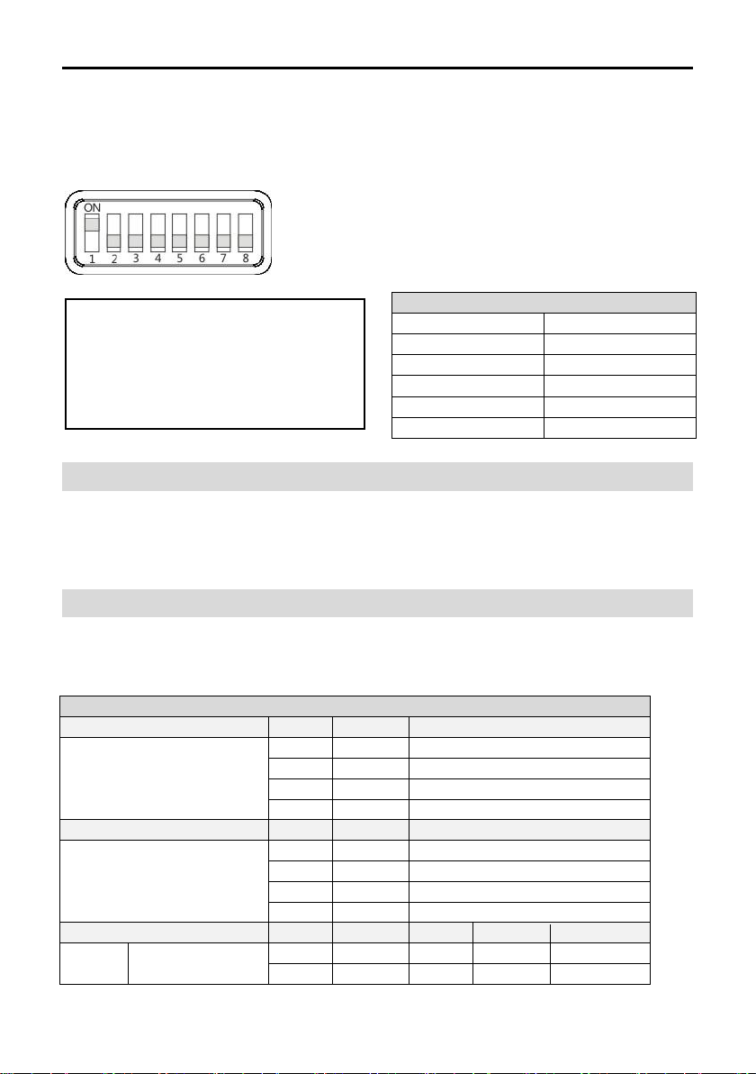
DIP SWITCHES SETTINGS ------------------------------------------------------------------- 3
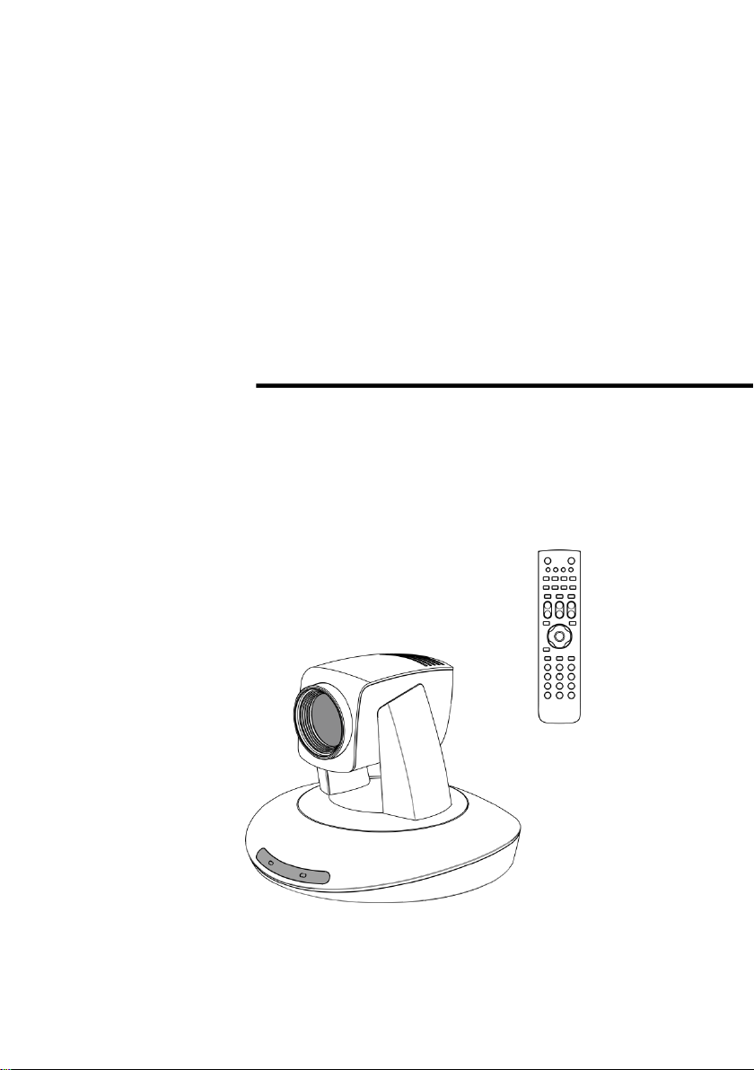
REMOTE CONTROLLER --------------------------------------------------------------------- 5
CONNECTIONS ---------------------------------------------------------------- 7
INSTALLATION ---------------------------------------------------------------- 8
DESKTOP MOUNT INSTALLATION ------------------------------------------------------------ 8
WALL MOUNT INSTALLATION ---------------------------------------------------------------- 8
CEILING MOUNT INSTALLATION-------------------------------------------------------------- 9
MENU SETTINGS ------------------------------------------------------------ 10
MENU CONFIGURATION-------------------------------------------------------------------- 10
MENU EXPLANATION ---------------------------------------------------------------------- 14
VIDEO ----------------------------------------------------------------------------------- 15
EXPOSURE ------------------------------------------------------------------------------- 15
WHITE BALANCE -------------------------------------------------------------------------- 16
PAN/TILT/ZOOM--------------------------------------------------------------------------- 17
SYSTEM---------------------------------------------------------------------------------- 17
STATUS ---------------------------------------------------------------------------------- 18
RESTORE DEFAULTS ---------------------------------------------------------------------- 18
ANNEX 1 TECHNICAL SPECIFICATIONS------------------------------------ 19
ANNEX 2 SIZE AND DIMENSION -------------------------------------------- 20
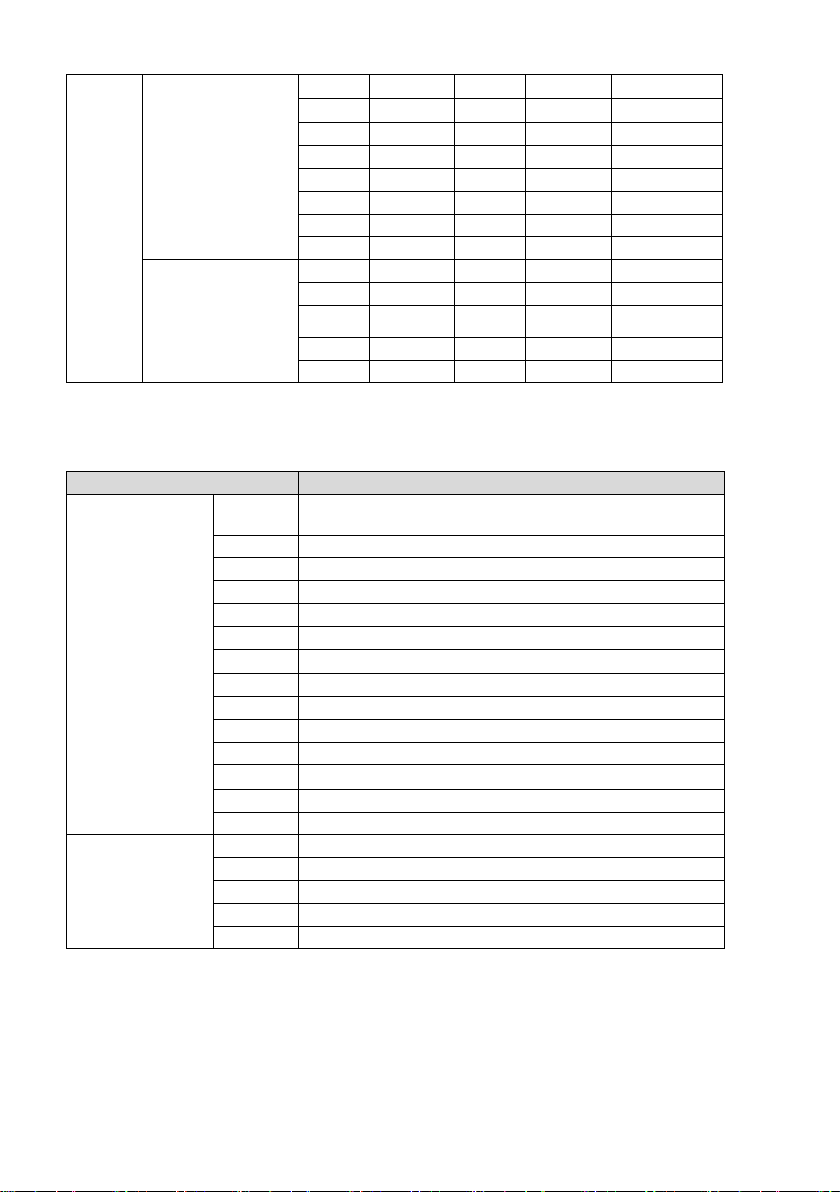
ANNEX 3 SW1 DEFINITION -------------------------------------------------- 21
TROUBLESHOOTING-------------------------------------------------------- 23


1
ABOUT THE PRODUCT
Features
1/2.8 inch Exmor CMOS sensor, 2.14
megapixel;
Supports full resolution up to1080p60 and
SD video formats;
Simultaneous outputs of HD and SD videos;
HD video interfaces: 3G-SDI, DVI-I;
OSD menu;
20x optical zoom, 12x digital zoom/30x
optical zoom, 12x digital zoom;
Precise driving system with high reliability
and precision;
Support VISCA , Daisy chain and Pelco
protocols;
With IR remote controller;
Smart AE technology to effectively avoid
the interference of complicated lights from
projectors ,monitors etc;
Desktop/Ceiling/ Wall mount optional.
List Of Parts & Accessories
When you open the box, check all accessories
according to the packing list.
Camera (1)
Power Adapter (1)
Remote Controller (1)
Cable Package (1)

2
Main Parts & Interfaces
Camera
Front View
1 Camera Module
2 Communication Indicator
3 Power Indicator
4 Remote Controller Indicator
Rear View
5 DVI-I interface
6 3G-SDI interface
7 Composite interfaces (CVBS output,
RS-485/RS-422, RS-232 in and RS-232 out)
8 DC12V power input
Bottom View
9 DIP Switch
Set camera address, protocol, baud rate,
video format and mounting type.
10 Mounting Hole
1/4”inch screw thread for fixing camera.
11 Locating Hole
To define installation direction of camera.

3
DIP Switches Settings
Before operating the camera, set the camera address, DVI-I output signal format and video format
etc through DIP switches. The camera has two DIP switches: SW1 and SW2 as below:
Sw1 Settings
No 1~6 are used to set address for camera, the DIPs adopt binary system. No. 7 is used to set
analog video format. No. 8 is used to set mounting type. Refer to page 22 for details.
Sw2 Settings
No. 1 and 2 of SW2 is used to set protocol; no. 3 and 4 is used to set baud rate; no. 5, 6, 7, 8 is
used to set video output format. Refer to below chart for details:
SW2
DIP No.
1
2
Protocol
OFF
OFF
VISCA
ON
OFF
PELCO- D
OFF
ON
PELCO- P
ON
ON
Reserved
DIP No.
3
4
Baud Rate(bps)
OFF
OFF
2400
ON
OFF
4800
OFF
ON
9600
ON
ON
38400
DIP No.
5
6
7
8
Video
Format
OFF
OFF
OFF
OFF
1080p60
ON
OFF
OFF
OFF
1080p50
Default Settings
Address
1
Baud Rate
9600bps
Protocol
VISCA
Video Format
1080i50
Analog Video Format
YPbPr
Mounting Type
Stand
Note
SW1 is used to set address, video output
and mounting type, SW2 is used to set
protocol, baud rate and video format.

4
OFF
ON
OFF
OFF
1080i60
ON
ON
OFF
OFF
1080i50
OFF
OFF
ON
OFF
720p60
ON
OFF
ON
OFF
720p50
OFF
ON
ON
OFF
1080p30
ON
ON
ON
OFF
1080p25
OFF
OFF
OFF
ON
720p30
ON
OFF
OFF
ON
720p25
Only availlable for
30X model
OFF
ON
OFF
ON
1080p59.94
ON
ON
OFF
ON
1080p29.97
OFF
OFF
ON
ON
1080i59.94
ON
OFF
ON
ON
720p59.94
OFF
ON
ON
ON
720p29.97
When No.5~8 is all ON, video format can be switched by calling preset, Refer to below chart for
details:
Preset No.
Function
93
Cruise, camera switches among saved 0~29 presets
repeatedly and sequentially in fixed interval.
95
Get into menu
96
Delete all presets
99
System reboot
100
1920X1080p50
101
1920X1080p25
102
1920X1080i50
103
1280X720p50
104
1280X720p25
105
1920X1080p60
106
1920X1080p30
107
1920X1080i60
108
1280X720p60
109
1280X720p30
Only availlable for
30X model
110
1920X1080p59.94
111
1920X1080p29.97
112
1920X1080i59.94
113
1280X720p59.94
114
1280X720p29.97
When HD video output format is set as 1080p60, 1080p30,1080i60, 720p30 or 720p60, relative SD
video format is NTSC; when HD video output format is set as 1080p50, 1080p25,1080i50, 720p25
or 720p50, relative SD video format is PAL.

5
Remote Controller
1 HOME
Press HOME button, camera moves to
initial position where both pan and tilt angle
is zero.
2 Camera Selection Button
Used to switch among 4 cameras, press 1-4
number buttons to control cameras with 1-4
addresses respectively. For example, press
button 1 to control the camera with address
1.
3 Focus
Press“AUTO”button to switch to Auto Focus,
press “MANU” button to switch to Manual
Focus mode.
“ ”button to Focus Near
“ ”button to Focus Far
“ ”button to Auto Focus once every time
it is pressed, then switch back to Manual
Focus mode.
4 Iris
Press“ ”button to reset iris value to
default. “ ”button to Iris Open
“ ”button to Iris Close.
5 Menu
Press MENU button to enter / exit menu.
6 Data
Press DATA button to set on / off the
display of pan tilt angel, zoom times and
other prompt message.
7 Number Keys
Used to input numbers, for example, preset
number.

6
8 Cancel
To cancel numbers input
9 Power
After the camera has been connected to
power source, in none-menu status, press
this button to turn on / off the camera.
10 Reserved Buttons(F1, F2, F3, F4)
These buttons are reserved for future use.
11Pattern
Used to activate Pattern Scan1 and Pattern
Scan2.
12 BLC
Used to open / close back light
compensation.
13 Zoom
Used to adjust zooming times.
“ ”button to zoom in
“ ”button to zoom out.
14 Back
Press“”button to go back to previous
menu.
15 OK
In None-menu status: press this button to
switch among pan / tilt control speeds.
In Menu status: get into relative menu
option after it has been selected.
16 Direction / Menu Operation
In None-menu status, press these four
buttons to pan left/right and tilt up/down.
In Menu status: or button to select
among menu options, or to change
option / value.
17 Preset Setting
“ ” button to call a preset.
Input number key(s), and then press this
button to call a preset.
“ ”button to set a preset.
Move the camera to a specific position,
adjust focus value and etc, and then press
this button to set a preset.
“ ”button to clear a preset.
Input number key(s), and then press this
button to clear a preset.
18 Enter
After inputting numbers, press this button to
confirm.

7
CONNECTIONS
Note
If preset 0 has been saved, after powered on, camera moves to preset 0 automatically; if
preset 0 has not been saved, after powered on, camera moves to Home position, where both
pan and tilt angle is zero and zooming time is 1x.

8
INSTALLATION
The camera has 3 installation types: desktop,
ceiling, wall mount installations.
Desktop Mount Installation
1. Put the camera on a flat surface. In case
the camera has to be placed on an
inclined surface, make sure the cline
angle is less than 15 degrees to ensure
proper pan /tilt operation.
Wall Mount Installation
Not Supplied With Camera
1. According to diameter and position of the
4 installation holes (As shown below) on
the bracket, drill 4 holes on the wall and fix
the bracket onto the wall by using 4
screws which should be prepared by you.
2. Before fixing the camera, set the DIP
switches of the camera correctly.
Note
Take effective measures to avoid camera
from dropping.
Do not grab the camera head when
carrying.
Do not rotate the camera head with
hand. It may cause malfunction to the
camera.
Note
Before installing, make sure there is
enough space to install the camera and its
parts.
Make sure the installed place is strong and
safe enough to hold the camera and
relative parts, it is suggested that the
installed place can withstand 4 times the
weight of the camera and its relative parts.

9
3. Use inch screws to fix the camera on the
bracket, fix the limit screw according to
actual requirement, and make sure the
camera is tightly fixed onto the bracket
before your hands leave the camera.
Ceiling Mount Installation
Not Supplied With Camera
1. According to diameter and position of the
3 installation hole (as shown below), drill 3
holes on the ceiling or cement roof
correspondingly.
2. Fix the mounting plate onto the ceiling or
cement roof with 3 screws which should
be prepared by you.
3. Before fixing the camera, set the DIP
switches of the camera correctly.
4. Use 3 screws to fix the camera on the
ceiling mount plate.
5. Push forward camera's bottom slide
according to the mounting plate’s bottom
slide until they reach their limit. Fix the
ceiling mount plate and camera’s bottom
plate with M3×8 screws.

10
MENU SETTINGS
Menu Configuration
<VIDEO>
Refer to
SHARPNESS
0, 1, 2, 3, 4, 5, 6, 7, 8, 9, 10, 11, 12, 13, 14, 15
Page 15
BRIGHTNESS
-7, -6, -5, -4, -3, -2, -1, 0, +1, +2, +3, +4, +5,
+6, +7
CONTRAST
-7, -6, -5, -4, -3, -2, -1, 0, +1, +2, +3, +4, +5,
+6, +7
SATURATION
-7, -6, -5, -4, -3, -2, -1, 0, +1, +2, +3, +4, +5,
+6, +7
HUE
-7, -6, -5, -4, -3, -2, -1, 0, +1, +2, +3, +4, +5,
+6, +7
2DNR LEVEL
LOW, MID, MAX, OFF
3DNR LEVEL
LOW, MID, MAX, OFF
WIDE DYNAMIC
ON, OFF

11
<EXPOSURE>
Refer to
Page 15
MODE
FULL AUTO
MANUAL
GAIN
0, +2, +4, +6, +8, +10,
+12, +14, +16, +18, +20,
+22, +24, +26, +28
SPEED
1/1, 1/2, 1/3, 1/6, 1/12,
1/25, 1/50, 1/75, 1/100,
1/120, 1/150, 1/215,
1/300, 1/425, 1/600,
1/1000, 1/1250, 1/1750,
1/2500, 1/3500, 1/6000,
1/10000
IRIS
F14, F11, F9.6, F8, F6.8,
F5.6, F4.8, F4, F3.4, F2.8,
F2.4, F2, F1.6, CLOSE
SHUTTER PRI
SPEED
1/1, 1/2, 1/3, 1/6, 1/12,
1/25, 1/50, 1/75, 1/100,
1/120, 1/150, 1/215,
1/300, 1/425, 1/600,
1/1000, 1/1250, 1/1750,
1/2500, 1/3500, 1/6000,
1/10000
IRIS PRI
IRIS
F14, F11, F9.6, F8, F6.8,
F5.6, F4.8, F4, F3.4, F2.8,
F2.4, F2, F1.6, CLOSE
SMART
AREA1
AREA2
AREA3
AREA4
PRESET 001~255
PRESET 001~255
PRESET 001~255
PRESET 001~255
EXP-COMP
ON
LEVEL
-7, -6, -5, -4, -3, -2, -1, 0,
+1, +2, +3, +4, +5, +6, +7
OFF
BLC
ON, OFF

12
<WHITE BALANCE>
Refer to Page 16
MODE
AUTO
ATW
ONE PUSH
INDOOR
OUTDOOR
MANUAL
R.GAIN
0~255
B.GAIN
0~255
<PAN TILT ZOOM>
Refer to Page 17
PAN/TILT SPEED
1, 2, 3, 4, 5, 6, 7, 8
PAN/TILT LIMIT
ON, OFF
UP
-30°~+90°
DOWN
-30°~+90°
LEFT
-170°~+170°
RIGHT
-170°~+170°
D-ZOOM LIMIT
X1, X2, X3, X4, X5, X6, X7,
X8, X9, X10, X11, X12
PTZ TRIG AF
ON, OFF
POWER UP ACTION
PRESET 1, PRESET 2,
PRESET 3, PRESET 4,
PRESET 5, PRESET 6,
PRESET 7, PRESET 8,
PRESET 9, HOME

13
<SYSTEM>
Refer to
Page 18
DISPLAY INFO
ON, OFF
RATIO SPEED
ON, OFF
PRESET FREEZE
ON, OFF
CVBS OUTPUT
SQUEEZE, CROP, LETTER BOX
RS422 PORT
HALF-DUPLEX-1, HALF-DUPLEX-2,
FULL-DUPLEX
<STATUS>
Refer to
Page 18
ADDRESS 1
PROTOCOL VISCA
BAUDRATE 9600
VIDEO FORMAT 1080i50
DVI-I OUTPUT YPBPR
MOUNT MODE STAND
FIRMWARE VER V1.2.5
<RESTORE DEFAULTS> Refer to Page 18

14
Menu Explanation
Main Menu
Press MENU button to enter / exit menu.
❶Menu Hint
It displays currently selected menu option.
❷Menu Options
It displays options under current menu
hint.
Press or button to select among
menu options, once font of options turned
from white color to yellow color, it indicates
the menu has been elected, press OK
button to get into this menu.
❸Prompt Message
“SELECT”indicates it is possible to
press or button to select menu
options.
“NEXT”indicates it is possible to
press OK button to enter next level menu.
“EXIT”indicates it is possible to
press MENU button to exit menu.
Submenus
From main menu, navigate to select
<EXPOSURE> menu, press OK to enter.
❶Menu Hint
It displays currently selected menu option.
❷Menu Options
It displays options under current menu
hint.
Press or button to select among
menu options, once font of options turned
from white color to yellow color, it indicates
the menu has been elected, press OK
button to get into this menu.
❸Manual Exposure
Press or button to change value.
❹Prompt Message
“SELECT” indicates it is possible to
press or to select menu options, press
or to change value
“BACK”indicates it is possible to press
to return to previous menu.
<EXPOSURE>
MODE MANUAL
GAIN 0
SPEED 1/50
IRIS F14
EX-COMP ON
LEVEL 0
BLC OFF
SELECT BACK
<MENU>
VIDEO
EXPOSURE
WHITE BALANCE
PAN TILT ZOOM
SYSTEM
STATUS
RESTORE DEFAULTS
SELECT NEXT EXIT
❶
❷
❸
❶❸
❷
❹
Table of contents