18-4
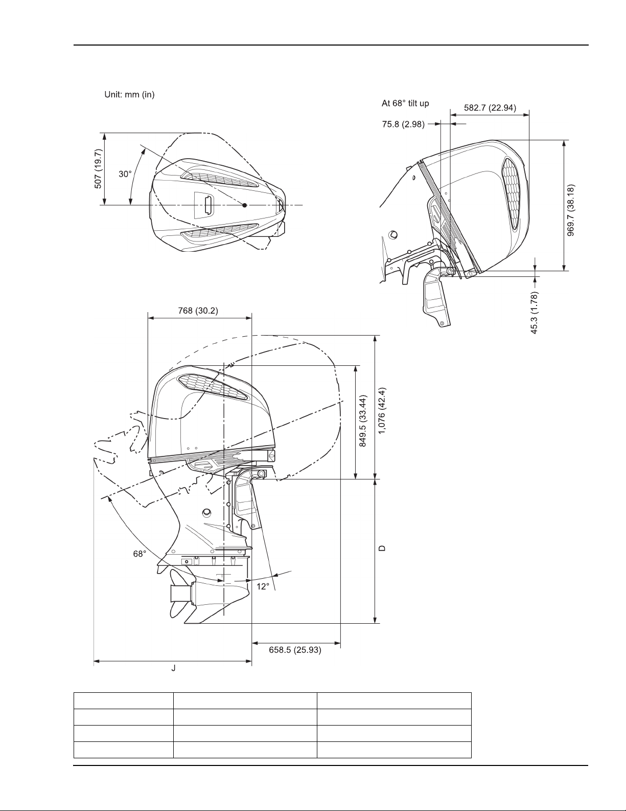
18. BF200D • BF225D • BF250D iST®
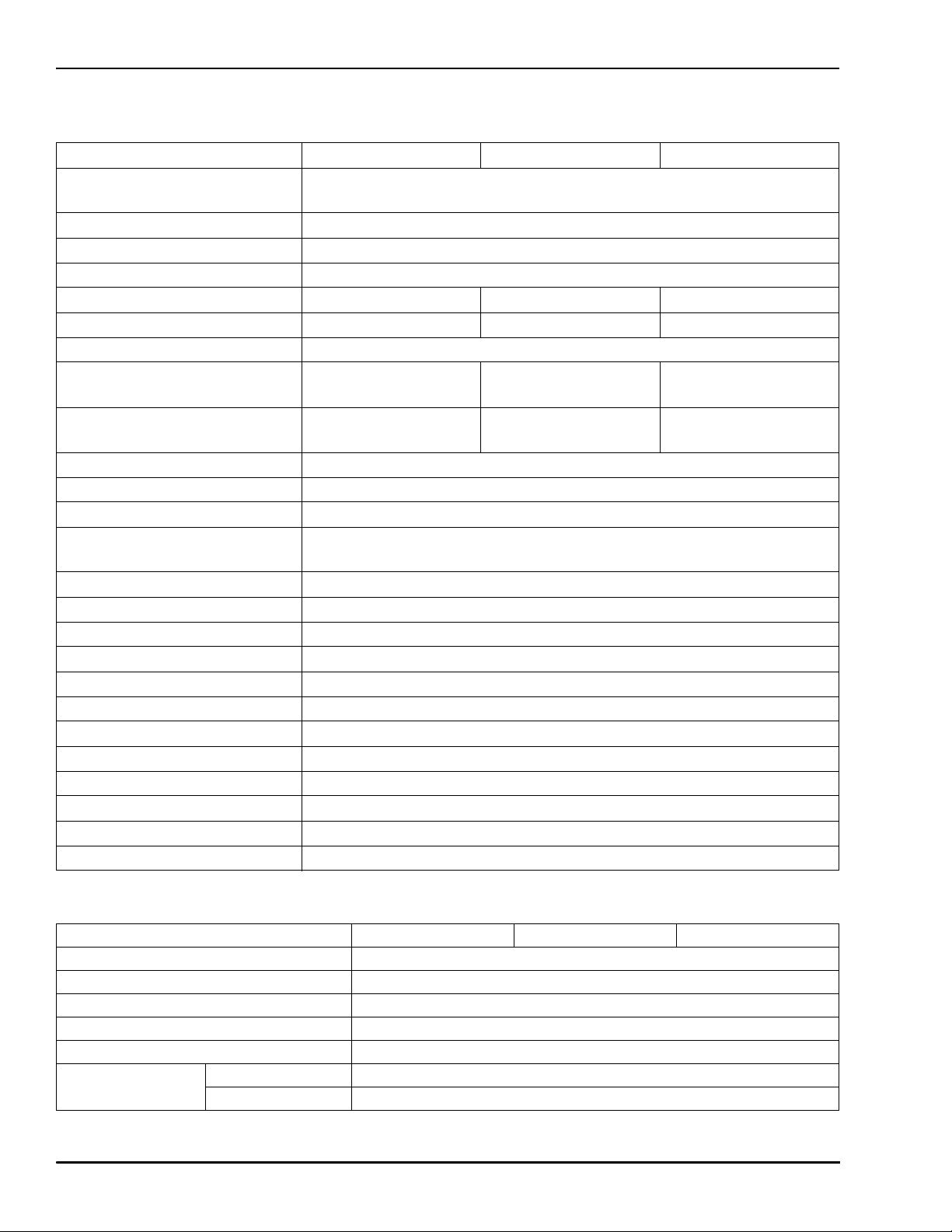
SPECIFICATIONS
ENGINE
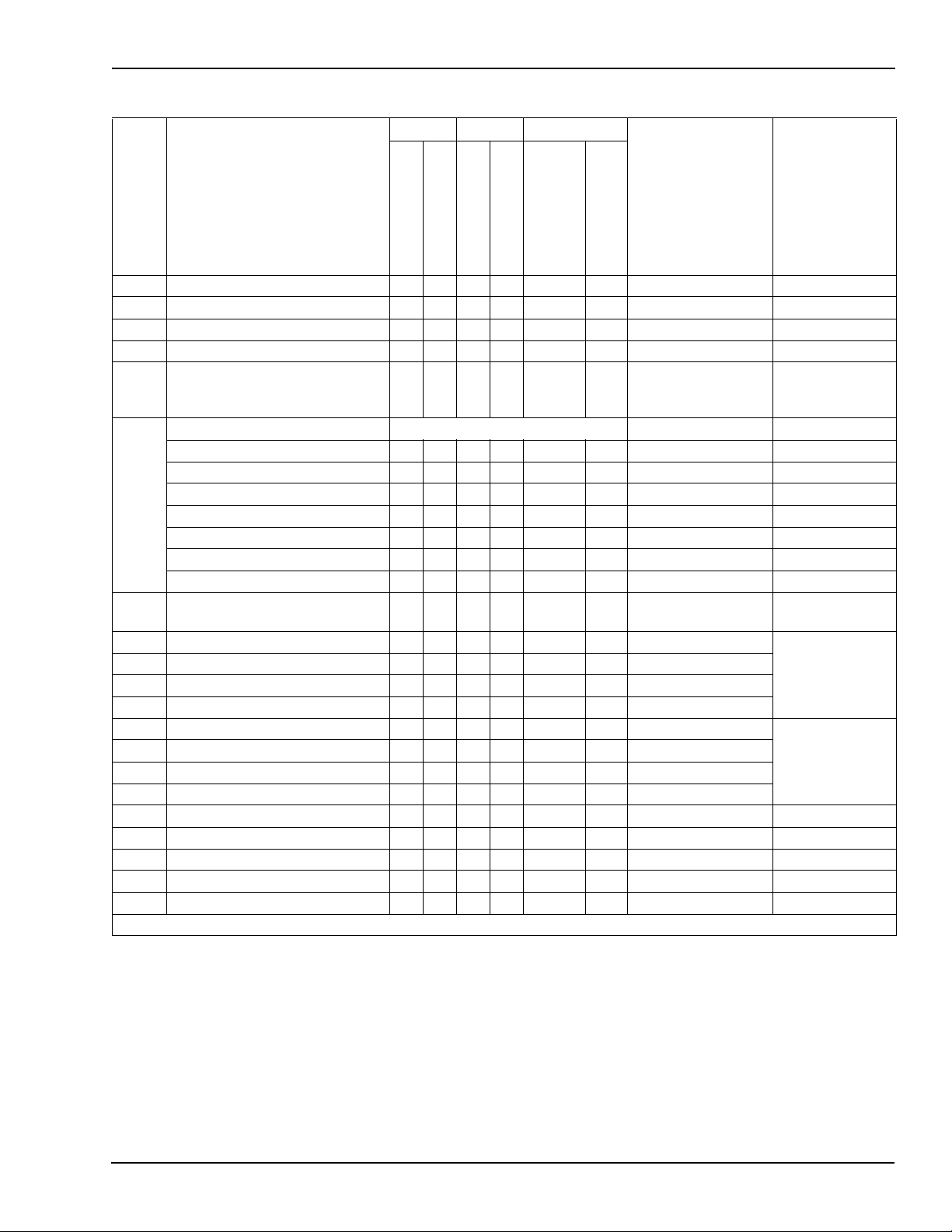
LOWER UNIT
Model BF200D BF225D BF250D
Type Water-cooled, 4-stroke, SOHC,
60° V6, VTEC
Displacement 3,583 cc (218.6 cu in)
Bore x stroke 89 x 96 mm (3.5 x 3.78 in)
Full throttle range 5,000 - 6,000 rpm
Rated horsepower 200 hp @ 5,500 rpm 225 hp @ 5,500 rpm 250 hp @ 5,800 rpm
Maximum torque @ 4,000 rpm 229 lbf-ft 232 lbf-ft 236 lbf-ft
Compression ratio 10.0:1
Fuel consumption ratio
(at rated power) 320 g/kW•h 300 g/kW•h 320 g/kW•h
Fuel consumption ratio
(at continuous max. power) 320 g/kW•h 300 g/kW•h 320 g/kW•h
Cooling system Forced water circulation by impeller pump with thermostat
Ignition system Full-transistorized battery
Ignition timing 0° at 650 rpm BTDC
Spark plug ZFR6K-11E (NGK) - standard
IZFR6F 11 (NGK) - optional
Fuel supply system Programmed fuel injection
Fuel injection system Electronic control
Fuel injection nozzle Multi-point type
Lubrication system Pressure lubrication by trochoid pump
Oil capacity 8.8 L (9.3 qt)
Recommended oil Honda Marine genuine engine oil SAE 10W-30, FC-W™
Starter system Electric starter
Battery system 1040 MCA (800 CCA, 110 AH) minimum (engine only)
Stopping system Primary circuit ground
Fuel used Unleaded gasoline (minimum 86 pump octane)
Fuel pump Electromagnetic type
Exhaust system Underwater type
Model BF200D BF225D BF250D
Clutch Dog clutch (forward-neutral-reverse)
Gear ratio 2.00:1 (24/12)
Reduction type Spiral bevel gear
Gear case oil capacity 1.47 L (1.55 qt)
Recommended gear case oil Marine SAE 90, API service designation GL4
Propeller rotation
(viewed from rear)
Clockwise LDA, UDA, XDA, types
Counterclockwise UCDA, XCDA types