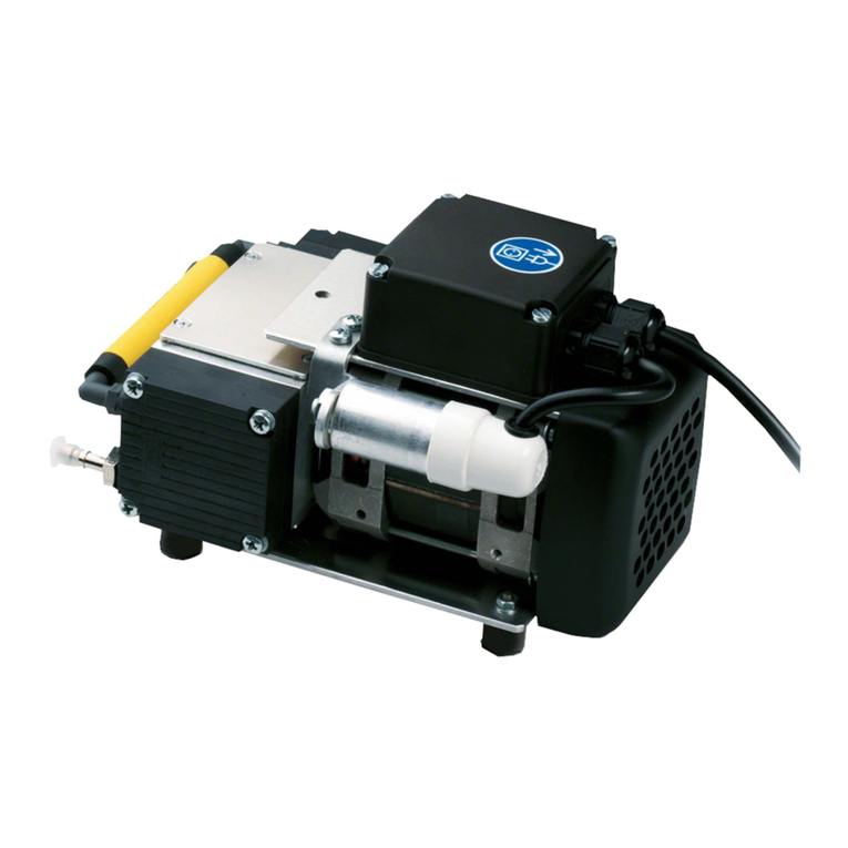
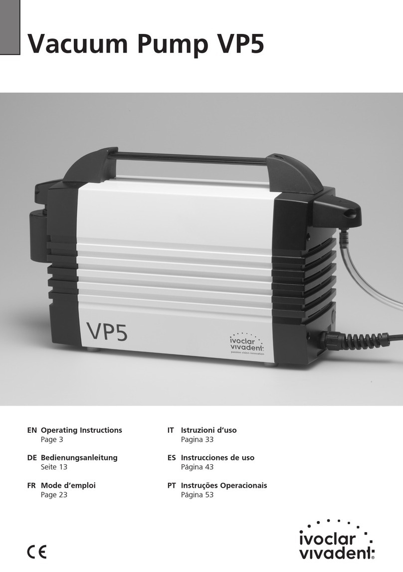
Ivoclar Vivadent VP4 User manual

Vacuum Pump VP4
Operating Instructions
Page 3
Bedienungsanleitung
Seite 13
Mode d’emploi
Page 23
Istruzioni d’uso
Pagina 33
Instrucciones de uso
Página 43
Instruções Operacionais
Página 53

2

3
Vaccum Pump VP4
Page
List of Parts 4
1. Introduction / Signs and Symbols 5
1.1 Preface
1.2 Introduction
1.3 Signs and symbols
2. Safety First 6
2.1 Indications
2.2 Health and safety instructions
3. Product Description 7
3.1 Components
3.2 Functional description
3.3 Hazardous areas and safety equipment
4. Installation 8
4.1 Unpacking and checking the contents
4.2 Selecting the location
4.3 Making the connections
4.4 Mounting the sound absorber
5. Start-Up 9
6. Operation 9
7. Maintenance, Cleaning, and Diagnosis 10
7.1 Monitoring and Maintenance
7.2 Cleaning
7.3 Notes on maintenance
8. What If... 11
8.1 Technical malfunctions
8.2 Repairs
9. Product Specifications 12
9.1 Delivery from
9.2 Technical data
9.3 Acceptable operating conditions
9.4 Acceptable transportation conditions
english

4
8
9
7
8
6
4
10
13
1
3
2
512
List of Parts
1 Cable connection with
bend protection
2 Power cord
3 Air vents
4 Vacuum hose
connection
5 Housing
6 Connection tube
7 Transportation grip
8 Sound absorber
9 Sound absorber
connection
10 Fuse (inside)
11 Protective cap
12 Rating plate
13 Rubber feet
11

5
1.1 Preface
Dear Customer
Thank you for having purchased the Programat®Vacuum
Pump. This apparatus is a high-quality, technical product.
Please read the Operating Instructions carefully and use
the apparatus according to the Instructions. Should you
have any further questions, please do not hesitate to
contact your local distributor or Ivoclar Vivadent AG
directly.
1.2 Introduction
Apparatus: VP4 Vacuum Pump
Target group: Dental lab personnel
This vacuum pump is suitable for evacuating the firing
chamber of the Programat ceramic furnace. It is a quietly-
running double-diaphragm pump with high vacuum
performance.
These Operating Instructions aredesigned to assurethe
correct, safe, and economic use of the VP 4 Vacuum
Pump. They are divided into several, clearly structured
chapters to help you find specific topics quickly and easily.
Signs and symbols (pictographs) areused to inform you
quickly and clearly about health risks, important details,
and contraindications.
We recommend keeping the Instructions in a safe place
near the pump so that they are immediately accessible if
necessary. Should you lose the Operating Instructions,
extra copies can be ordered at a nominal fee from your
local Ivoclar Vivadent Service Center.
1.3 Signs and symbols
The signs and symbols in these Operating Instructions and
on the pump facilitate the finding of important points and
have the following meanings:
Operating Instructions:
Risks and dangers
Information
Contraindication
Pump:
Alternating current
1. Introduction / Signs and Symbols

6
2. Safety First
This chapter is especially important for personnel who
work with the VP 4 Vacuum Pump or who have to carry
out maintenance or repair work. This chapter must be
read and the corresponding instructions followed.
2.1 Indications
This vacuum pump has been developed especially for the
evacuation of Programat ceramic furnaces from Ivoclar
Vivadent and it should be used for this purpose only.
Other uses than the ones stipulated are contraindicated.
The manufacturer does not assume any liability for
damage resulting from misuse. The user is solely
responsible for any risk resulting from failure to observe
these Instructions.
Further instructions to assureproper use of the pump:
– The instructions, regulations, and notes in the vacuum
pump Operating Instructions must be observed.
– The pump must be operated under the indicated
environmental and operating conditions (Chapter 9).
– The VP 4 must be properly maintained.
2.1.1
Risks and
dangers
Foreign objects or liquids
must not enter the air vents,
since this may block the
motor or result in an
electrical shock.
2.1.2
Risks and
dangers
The connection cover must
not be opened while the
pump is connected to the
power socket, since this may
result in an electrical shock.
The connection cover may
only be opened by the
personnel of a certified Ivoclar Vivadent Service Center.
2.2 Health and Safety Instructions
– Make sure that the pump is only used for the
indications stipulated in these Operating Instructions.
– Do not use the pump in areas where there is an
explosion hazard.
– Components connected with the pump must comply
with the pneumatic data of the pump.
– Observe the corresponding safety regulations when
connecting the pump to the electronic network.
– If the operation of the pump is interrupted by the
thermoswitch because of over-heating, the pump
starts automatically once it has cooled down. Make
sure that no danger results from such an incidence.
– Observe the corresponding safety instructions for the
media used.
– Use only original spare parts.
– The pump complies with the safety regulations of the
following EC guidelines:
73/23 EEC (low voltage guideline)
89/336/EEC (electromagnetic compatibility)
– If the pump has been stored at very low temperatures
or high atmospheric humidity,the pump has to be
dried or left to adjust to the room temperature for
approx. 1 hour (do not connect to the power yet).
Do not work with liquids near the pump.
Should a liquid accidentally enter the pump,
disconnect power and consult Customer
Service. Do not operate the pump
– The pump is tested for use at altitudes of up to
2000 m above sea level.
– The furnace may only be used indoors.
– The unit must not be technically modified.
The connection cover, which is marked with the label
shown below, may only be opened once the power has
been disconnected (interruption of the power supply)
by qualified service personnel. Please observe the rele-
vant rules and regulations, as well as other recognized
safety and medical regulations.

7
Any disruption of the protective conductor
either inside or outside the pump or any
loosening of the protective conductor
connection may lead to danger for the user in
case of malfunction. Deliberate interruptions
are not tolerated.
Do not use furnaces of other manufacturers
that are not coordinated with the pump. Ask
the corresponding manufacturer for further
details. The vacuum pump has been especially
developed for use with the Programat ceramic
furnaces and must be used for this purpose
only.
Disposal:
The furnace must not be disposed with the
common domestic waste. Please correctly
dispose old furnaces according to the
European WEEE Directive (Waste Electrical
and Electronic Equipment).
3.1 Components
The VP 4 Vacuum Pump consists of the following
components:
– Vacuum pump with power cord
– Vacuum hose (accessory)
3.2 Functional description
The diaphragm squeezed between the cylinder head and
the housing is moved up and down by a con-rod. By
means of this movement and by suction and eduction
valves in the cylinder head, the firing and/or press chamber
of the furnace is evacuated and the vacuum is built up.
3.3 Hazardous areas and safety equipment
Description of the hazardous areas of the pump:
Description of the safety features of the pump:
3. Product Description
Hazardous area
Fuse holder
Ventilator
Type of risk
Electrical shock
Injury
Safety equipment
Protective conductor
IP20 (protection type)
Thermoswitch
Ventilator cover
Protective effect
Protection from electrical
shock
Protection from electrical
shock
Protection from
overheating
Protection from electrical
shock and injury

8
4.1 Unpacking and checking the contents
Remove the pump from its packaging and check it for any
transportation damage. We recommend keeping the
original packaging for any transportation purposes. Use
only the original packaging for shipping.
The vacuum pump features a carrying handle (7).
Use only this handle to carry the pump.
4.2 Selecting the location
Place the pump on a flat surface using the rubber feet
(13). Make sure the pump is not exposed to direct sun-
light. Do not place the pump in the immediate vicinity of
heaters or other sources of heat. Make sure that there is
enough space for air circulation between the wall and the
air vents (3).
Make sure to select the location in such a way that the
sound absorber is not knocked off by accidentally abutting
against laboratory furniture.
4.3 Making the connections
Checking the rating plate and power supply
Make sure that the voltage indicated on the rating plate
(12) complies with the local power supply.Should this not
be the case, do not connect the pump.
Connecting the vacuum hose
Remove protective cap (11) from the vacuum hose
connection (4) and slip vacuum hose on the vacuum hose
connection (4). Connect the other end of the vacuum
hose with the furnace.
Please check if the hose is properly connected.
Connecting the power
Plug power plug of the power cord (2) into the
corresponding socket in the Programat. This is the power
supply at the same time.
The electrical installation in the room where the
pump is used must comply with the local and IEC
requirements.
4.4 Mounting the sound absorber
The sound absorber must be mounted prior to setting
the VP 4 Vacuum Pump in operation. Mount the sound
absorber (8) at the sound absorber connection (9) (see
picture below).
The sound absorber is supplied dismounted to
avoid damage during transportation.
In combination with a press or combination furnace (e.g.
Programat EP5000, EP600, EP600 Combi), it is necessary
to use the sound absorber Type P (large) in order to
prevent plugging of the sound absorber.
Sound absorber for the Vacuum Pump VP 4
– Sound absorber Type B (small)
551 718 (e.g. Programat P300, P500, P700)
–Sound absorber Type P (large), incl. distance tube
561 756 (e.g. Programat EP 5000)
.
4. Installation
87
9
Type B Type P
distance tube

9
The vacuum pump is automatically controlled by the
furnace, once the power cord of the pump has been
connected with the Programat furnace.
The pump is operated by the furnace programs.
5. Start-Up 6. Operation

10
7. Maintenance and Cleaning
For safety reasons, disconnect power plug before
maintenance and cleaning.
7.1 Monitoring and Maintenance
Basically, the diaphragm vacuum pump does not require
maintenance unless the performance deteriorates due to
contamination. Therefore, conduct a vacuum test at least
once a year.
The time for maintenance procedures depends on the
frequency of use and the location of the pump. For that
reason the recommended times are only approximates.
This apparatus has been developed for typical use
in the dental laboratory.
If the product is used in a production facility, for industrial
applications, or in continuous operation, premature ageing
of certain spare parts have to be expected.
These spareparts are e.g.:
– Sound absorber
– Diaphragm
– Valve reed
These spareparts are not covered by the warranty.
Please also observe the shorter service and maintenance
intervals.
7.2 Cleaning
Remove dust from the pump from time to time. Use a
vacuum cleaner with a cleaning brush for that purpose.
7.3 Notes on maintenance
The diaphragm may only be changed by an
Ivoclar Vivadent Service Center. The fuse must be
changed by qualified personnel.
Please observe the relevant rules and regulations for the
prevention of accidents as well as the safety and medical
regulations. The connection cover that is marked with the
label shown below may only be opened by qualified
personnel after the power has been disconnected.
What
Check all plug-in
connections for
correct fit.
Check the hose
to make surethat
no condensation
water has
accumulated in
the system.
Part
Connections
Vacuum hose
When
Weekly
Weekly
Item
Housing
Sound absorber
(4)
Frequency
if required
if it is dirty
Cleaning material
soft, dry cloth
sound absorber
has to be
replaced

11
8. What If ...?
8.1 Technical malfunctions
8.2 Repairs
Repairs may only be carried out by the personnel of a certified
Ivoclar Vivadent Service Center. Please contact your Customer
Service representative.
Malfunction
1The pump is not working
2The vacuum performance is
declining or is bad
3Vacuum pump is unusually noisy
Double-check
– Is the pump correctly connected?
– Are the fuses OK?
– Has the thermoswitch been
activated because of overeating?
– Sound absorber clogged
– Has the test program for the
pump been carried out?
– Is the sound absorber defective or
incorrectly mounted?
– Is there a leak in the furnace
system or the pump?
Action
– Connect pump correctly.
– Have the fuses changed by
qualified personnel.
– Allow the pump to cool and
switch on again.
– Check pump location for
adequate circulation of air.
– If the problem cannot be solved,
contact your local Ivoclar Vivadent
Service Center.
– Replace sound absorber.
– Carry out the test program for the
pump (PX1).
– Send vacuum pump to Service
Center for maintenance.
– Connect sound absorber correctly
or replace it, if it is defective.
– Check connections and hose for
tightness.
– Clean sealing of the furnace head.
– Check pump performance with
the corresponding test program.

9.1 Delivery form
Vacuum pump
Operating Instructions
Warranty Card
9.2 Technical data
Power supply: 230 V / 50–60 Hz / 0.45 A
200 V / 50–60 Hz / 0.65 A
115 V / 50–60 Hz / 1.1 A
Tolerated voltage fluctuations: +/– 10%
Power consumption: 80 W
Suction strength: 19 l / min.
Final vacuum
(measured with a 4-liter test container): approx. 30 mbar
Dimensions: 320 x 110 x 212 mm (length, width, height)
Weight: 6.7 kg
Types of fuses: 230 V:1.0 AT 250 V
200 V: 1.6 AT 250 V
115 V: 2.5 AT 250 V
Safety information :
The VP 4 Vacuum Pump complies with the following
guidelines:
–EN 61010, Part 1, iEC 61010-1, UL 61010-1,
CSA 61010-1
–EMV tested
9.3 Acceptable operating conditions
– Ambient temperature range of:
+5 °C to +40 °C (+41 °F to +104 °F)
– Acceptable height:
The pump is tested for use at altitudes of up to
2000 m above sea level. Ambient pressure of 500 mbar to
1060 mbar.
– Pollution degree: 2
Overvoltage categorie: II
9.4 Acceptable transportation conditions
– Ambient temperature range of:
-10 °C to +55 °C (-4 °F to +131 °F)
– Maximum relative humidity: 80%
This apparatus has been developed for use in dentistry. Setup and
operation should be carried out strictly according to the Operating
Instructions. Liability cannot be accepted for damages resulting from
misuse or failure to observe the Instructions. The user is solely
responsible for testing the apparatus for its suitability for any purpose
not explicitly stated in the Instructions. Descriptions and data
constitute no warranty of attributes.
9. Product Specifications
12

13
deutsch
Vakuumpumpe VP 4 Seite
Teileverzeichnis 14
1. Einleitung und Zeichenerklärung 15
1.1 Vorwort
1.2 Einleitung
1.3 Zeichenerklärung
2. Sicherheit geht vor 16
2.1 Bestimmungsgemässe Verwendung
2.2 Sicherheits- und Gefahrenhinweise
3. Produktbeschreibung 17
3.1 Aufbau des Gerätes
3.2 Funktionsbeschreibung
3.3 Gefahrenstellen und Sicherheitseinrichtungen
4. Installation 18
4.1 Auspacken und Lieferumfang prüfen
4.2 Standortwahl
4.3 Anschlüsse herstellen
4.4 Schalldämpfer montieren
5. Inbetriebnahme 19
6. Bedienung 19
7. Unterhalt, Reinigung und Diagnose 20
7.1 Kontroll- und Unterhaltsarbeiten
7.2 Reinigungsarbeiten
7.3 Wartungshinweise
8. Was ist, wenn... 21
8.1 Technische Störungen
8.2 Reparaturarbeiten
9. Produktspezifikationen 22
9.1 Lieferform
9.2 Technische Daten
9.3 Zulässige Betriebsbedingungen
9.4 Zulässige Transportbedingungen

14
Teileverzeichnis
1 Kabelverschraubung
mit Knickschutz
2 Netzkabel
3 Lüftungsschlitze
4 Vakuumschlauch-
Anschluss
5 Gehäuse
6 Verbindungsschlauch
7 Transportgriff
8 Schalldämpfer
9 Schalldämpfer –
Anschluss
10 Sicherung (innen)
11 Schutzkappe
12 Typenschild
13 Gummifüsse
8
9
7
8
6
4
10
13
1
3
2
512
11

15
1.1 Vorwort
Sehr geehrter Kunde
Es freut uns, dass Sie sich für den Kauf der Programat
Vakuumpumpe entschieden haben. Bei diesem Gerät
handelt es sich um ein technisch hochstehendes Produkt.
Wir bitten Sie, die Bedienungsanleitung zu lesen und das
Gerät analog der Bedienungsanleitung in Betrieb zu
nehmen.
Wenn Sie noch zusätzliche Fragen haben, wenden Sie sich
bitte an das entsprechende Depot oder direkt an
Ivoclar Vivadent.
1.2 Einleitung
Zutreffendes Gerät: Vakuumpumpe VP 4
Zielgruppe: Zahntechnisches Fachpersonal
Diese Vakuumpumpe eignet sich für die Evakuierung der
Brennkammer beim Programat®Keramikbrennofen. Bei
dieser Pumpe handelt es sich um eine Membranpumpe
mit guter Vakuumleistung und kompakten Abmessungen.
Die Bedienungsanleitung (BA) dient zur sicheren, sachge-
rechten und wirtschaftlichen Nutzung der Vakuumpumpe
VP 4.
Die BA ist in mehrereKapitel unterteilt, die klar gegliedert
sind. Diese Aufteilung erleichtert ein schnelles Auffinden
der gewünschten Punkte.
Um Sie schnell und übersichtlich über Gefahren, wichtige
Informationen und nicht zulässige Anwendungen infor-
mieren zu können, werden an den Stellen entsprechende
Symbole (Piktogramme) verwendet.
Wir empfehlen Ihnen, die BA an einem geschützten Ort in
der Nähe des Gerätes aufzubewahren, sodass jederzeit ein
schneller Informationszugriff möglich ist. Bei einem even-
tuellen Verlust können Sie die BA gegen Schutzgebühr
über die entsprechende Ivoclar Vivadent Servicestelle
beziehen.
1.3 Zeichenerklärung
Die Symbole in der Bedienungsanleitung erleichtern Ihnen
das Auffinden wichtiger Punkte und geben Ihnen folgende
Hinweise:
In der Bedienungsanleitung:
Gefahren mit Risiken
Informationen
Nicht zulässige
Verwendungen
Auf dem Gerät:
Wechselstrom
1. Einleitung und Zeichenerklärung

16
2. Sicherheit geht vor
Dieses Kapitel ist für alle Personen, die mit dem Gerät
arbeiten oder am Gerät Unterhalts- oder Reinigungs-
arbeiten durchführen, zwingend zu lesen. Die Hinweise
sind zu befolgen.
2.1 Bestimmungsgemässe Verwendung
Die Vakuumpumpe wurde speziell für die Evakuierung der
Programat-Brennöfen der Ivoclar Vivadent entwickelt. Bitte
verwenden Sie dieses Gerät ausschliesslich für diesen
Zweck.
Eine andere oder darüber hinausgehende Benutzung gilt
als nicht bestimmungsgemäss. Für hieraus resultierende
Schäden haftet der Hersteller nicht. Das Risiko trägt allein
der Anwender.
Zur bestimmungsgemässen Anwendung gehören zudem:
– Die Beachtung der Anweisungen, Vorschriften und
Hinweise in der vorliegenden BA
– Der Betrieb unter den vorgeschriebenen Umwelt- und
Betriebsbedingungen (siehe Kapitel 9)
– Die korrekte Instandhaltung des Gerätes
2.1.1
Gefahren und
Risiken
Es dürfen keine Gegen-
stände oder Flüssigkeiten in
die Lüftungsschlitze gelan-
gen. Es könnte dadurch ein
Blockieren des Motors oder
ein Stromschlag verursacht
werden.
2.1.2
Gefahren und
Risiken
Der Anschlussdeckel darf
wegen Stromschlaggefahr
nicht geöffnet werden,
wenn das Gerät unter Netz-
spannung steht. Den
Anschlussdeckel darf nur
eine qualifizierte Servicestelle öffnen.
2.2 Sicherheits- und Gefahrenhinweise
– Beachten Sie, dass die Pumpe nur für den bestim-
mungsgemässen Gebrauch eingesetzt werden darf.
– Die Pumpen dürfen nicht in explosionsgefährdeter
Umgebung eingesetzt werden.
– Komponenten, die man an die Pumpe anschliesst,
müssen auf die pneumatischen Daten der Pumpen
ausgelegt werden.
– Beachten Sie beim Anschluss der Pumpen an das elek-
tronische Netz die entsprechenden Sicherheitsregeln.
– Wird der Pumpenbetrieb durch den Thermoschutz-
schalter wegen Überhitzung unterbrochen, so startet
die Pumpe nach der Abkühlung automatisch. Sorgen
Sie dafür, dass hieraus keine Gefahrensituationen ent-
stehen können.
– Für die zu verwendenden Medien sind die ent-
sprechenden Sicherheitsvorschriften zu beachten.
– Es dürfen nur Original-Ersatzteile verwendet werden.
– Die Pumpe entspricht den Sicherheitsbestimmungen
der EG-Niederspannungsrichtlinie 73/23 EWG und der
EG-Richtlinie über die elektromagnetische Verträglich-
keit 89/336 EWG.
– Wurde das Gerät bei grosser Kälte oder bei hoher Luft-
feuchtigkeit gelagert, ist vor der Inbetriebnahme (ohne
Spannung) die Pumpe bei Raumtemperatur einer Aus-
trocknungszeit bzw. einer Temperatur-Anpassungszeit
von zirka 1 Stunde zu unterziehen.
Nicht mit Flüssigkeiten über dem Gerät hantie-
ren. Sollte dennoch Flüssigkeit ins Gerät
gelangen, Stecker ziehen und den Kunden-
dienst konsultieren. Gerät nicht wieder in
Betrieb setzen.
– Das Gerät ist in Höhen bis 2000 m N.N. geprüft.
– Das Gerät darf nur in Innenräumen verwendet werden.
– Es dürfen am Gerät keine technischen Veränderungen
vorgenommen werden.
Der Anschlussdeckel, welcher mit dem untenstehenden
Hinweisschild gekennzeichnet ist, darf nur nach Ziehen
des Netzsteckers (Unterbrechen der Spannungsversor-
gung) durch Fachpersonal geöffnet werden. Beachten
Sie bitte die einschlägigen Vorschriften sowie die
sonstigen anerkannten sicherheitstechnischen und
arbeitsmedizinischen Regeln.

17
Jegliche Unterbrechung des Schutzleiters
innerhalb oder ausserhalb des Gerätes oder
Lösen des Schutzleiteranschlusses kann dazu
führen, dass bei einem auftretenden Fehler
das Gerät für den Betreiber eine Gefahr dar-
stellt. Absichtliche Unterbrechung ist nicht
zulässig.
Verwenden Sie keine Fremdöfen, die nicht auf
das Gerät abgestimmt sind. Erkundigen Sie
sich dabei beim entsprechenden Hersteller.
Die Vakuumpumpe wurde speziell für die
Programat-Brennöfen entwickelt und darf nur
für die dafür bestimmten Zwecke verwendet
werden.
Entsorgung:
Die Geräte dürfen nicht über den normalen
Hausmüll entsorgt werden. Bitte ausgediente
Geräte gemäss der EU-Richtlinie „EAG-VO“
fachgerecht entsorgen.
3.1 Aufbau des Gerätes
Die Vakuumpumpe VP 4 besteht aus folgenden
Komponenten:
– Vakuumpumpe mit Netzkabel
– Vakuumschlauch (Zubehör)
3.2 Funktionsbeschreibung
Die zwischen dem Zylinderkopf und dem Gehäuse einge-
klemmte Membrane wird über einen Pleuel auf- und abbe-
wegt. Durch diese Bewegung und die Ein- und Auslass-
ventile im Zylinderkopf wird die Luft aus der Brenn- bzw.
Presskammer des Ofens abgesaugt, sodass ein Vakuum
entsteht.
3.3 Gefahrenstellen und Sicherheitseinrichtungen
Bezeichnung der Gefahrenstellen:
Bezeichnung der Sicherheitseinrichtungen am Ofen:
3. Produktbeschreibung
Gefahrenstelle
Sicherungshalter
Lüfterrad
Art der Gefährdung
Stromschlag
Verletzung
Sicherheitseinrichtungen
Schutzleiter
IP20 (Schutzart)
Thermoschutzschalter
Abdeckung Lüfterrad
Schutzwirkung
Schutz vor Stromschlag
Schützt Pumpe vor
Überlastung
Schutz vor Stromschlag
und Verletzung

18
4.1 Auspacken und Lieferumfang prüfen
Gerät aus der Verpackung nehmen und auf eventuelle
Transportschäden überprüfen. Wir empfehlen, dass Sie die
Originalverpackung für eventuelle Versandzwecke aufbe-
wahren. Für den Versand verwenden Sie bitte nur die
Originalverpackung.
Die Vakuumpumpe verfügt über einen Tragegriff
(7). Tragen Sie die Pumpe ausschliesslich an
diesem Tragegriff.
4.2 Standortwahl
Stellen Sie das Gerät mit den Gummifüssen (13) auf eine
ebene Ablagefläche. Achten Sie darauf, dass das Gerät
nicht einer direkten Sonnenbestrahlung ausgesetzt ist.
Stellen Sie das Gerät nicht in unmittelbare Nähe von Heiz-
körpern oder anderen Wärmequellen. Beachten Sie, dass
zwischen Wand und Lüftungsschlitzen (3) genügend
Abstand für die Luftzirkulation vorhanden ist.
Achten Sie beim Aufstellen auch darauf, dass der Platz
so gewählt wird, dass der Schalldämpfer durch das ver-
sehentliche Anstossen an Labormöbeln nicht abgeschla-
gen werden kann.
4.3 Anschlüsse herstellen
Typenschild mit Spannung überprüfen
Bitte prüfen Sie, ob die auf dem Typenschild (12) angege-
bene Spannung mit derjenigen Ihres Netzes überein-
stimmt. Sollte dies nicht der Fall sein, darf das Gerät nicht
angeschlossen werden.
Vakuumschlauch anschliessen
Die Schutzkappe (11) des Vakuumschlauch-Anschlusses (4)
entfernen und den Vakuumschlauch auf den Vakuum-
schlauch-Anschluss (4) stecken. Das andere Schlauchende
mit dem Ofen verbinden.
Bitte prüfen Sie, ob der Schlauch einwandfrei aufgesteckt
ist.
Netzanschluss herstellen
Netzstecker des Netzkabels (2) in die entsprechende
Gerätesteckdose des Programats stecken. Dies ist zugleich
der Netzanschluss.
Die elektrischen Installationen des Raumes, in dem
sich das Gerät befindet, müssen den landes-
üblichen und den IEC Normen entsprechen.
4.4 Schalldämpfer montieren
Der Schalldämpfer muss vor Inbetriebnahme an die
Vakuumpumpe VP 4 montiert werden. Montieren Sie den
Schalldämpfer (8) am Schalldämpfer-Anschluss (9) (siehe
Abbildung).
Der Schalldämpfer (8) wird unmontiert geliefert,
um Transportschäden zu verhindern.
In Kombination mit einem Press- oder Kombiofen (z.B.
Programat EP 5000, EP 600, EP 600 Combi) muss immer
der Schalldämpfer Typ P (gross) verwendet werden, um
Verstopfungen des Schalldämpfers vorzubeugen.
Schalldämpfer für Vakuumpumpe VP 4
– Schalldämpfer Typ B (klein)
551 718 (z.B. Programat P300, P500, P700)
– Schalldämpfer Typ P (gross), inkl. Abstandsrohr
561 756 (z.B. Programat EP 5000)
4. Installation
87
9
Typ B Typ P
Abstandsrohr

19
Die Vakuumpumpe wird automatisch über den Ofen
angesteuert, wenn Sie das Netzkabel der Pumpe mit
dem Programat-Ofen verbinden.
Die Bedienung erfolgt über das Ofenprogramm.
5. Inbetriebnahme 6. Bedienung

20
7. Unterhalt, Reinigung und Diagnose
Aus sicherheitstechnischen Gründen bei sämt-
lichen Wartungs- und Reinigungsarbeiten den
Netzstecker aus der Gerätesteckdose ziehen.
7.1 Kontroll- und Unterhaltsarbeiten
Die Membran-Vakuumpumpe benötigt grundsätzlich keine
Wartung,, ausser die Leistung der Vakuumpumpe ver-
schlechtert sich durch Verschmutzung. Führen Sie aus die-
sem Grund min. einmal pro Jahr einen Vakuumtest aus.
Wann eine Wartungsarbeit durchgeführt werden soll,
hängt stark von der Gebrauchsintensität und dem Stand-
ort der Pumpe ab. Aus diesem Grund stellen die empfoh-
lenen Werte nur Richtwerte dar.
Dieses Gerät ist für den typischen Einsatz im
Detallabor entwickelt worden.
Falls das Produkt in einem Produktionsbetrieb, einer Indu-
strieanwendung oder im Dauerbetrieb eingesetzt wird,
muss mit einer vorzeitigen Alterung bzw. Verschmutzung
gerechnet werden.
Verschleissteile sind z.B.:
– Schalldämpfer
– Strukturmembrane
– Ventilplatte
Verschleissteile sind von der Garantieleistung ausgenom-
men. Bitte beachten Sie dazu auch die verkürzten
Service- und Wartungsintervalle.
7.2 Reinigungsarbeiten
Die Pumpe gelegentlich von Staub befreien.
Verwenden Sie dazu zum Beispiel einen Staubsauger mit
Reinigungspinsel.
7.3 Wartungshinweise
Der Membranwechsel darf nur von einer Ivoclar
Vivadent-Servicestelle durchgeführt werden. Der
Sicherungswechsel darf nur durch Fachpersonal
erfolgen.
Beachten Sie bitte die einschlägigen Unfallverhütungs-Vor-
schriften sowie die sonstigen anerkannten sicherheitstech-
nischen und arbeitsmedizinischen Regeln. Der Anschluss-
deckel, welcher mit dem untenstehenden Hinweisschild
gekennzeichnet ist, darf nur nach Ziehen des Netzsteckers
(Unterbrechen der Spannungsversorgung) vom qualifizier-
ten Servicetechniker geöffnet werden.
Was
Prüfen Sie, ob die
Steckverbindung
einwandfrei ist
Überprüfen Sie
den Schlauch,
damit kein Kon-
denswasser im
Leitungssystem
ist
Teil
Stecker
Vakuumschlauch
Wann
wöchentlich
wöchentlich
Was
Gehäuse
Schalldämpfer (4)
Wann
nach Bedarf
bei starker Ver-
schmutzung
Mit was
mit trockenem,
weichem Lappen
austauschen
Table of contents
Languages:
Other Ivoclar Vivadent Water Pump manuals
Popular Water Pump manuals by other brands

Waterway
Waterway CHAMPION series owner's manual

Pfeiffer Vacuum
Pfeiffer Vacuum Duo 2.5 Original operating instructions

Little Giant
Little Giant 1-AA-MD installation manual

Spartan
Spartan 740 Water Jet owner's manual

Larius
Larius Pegaso Operating and maintenance instruction

GORMAN-RUPP PUMPS
GORMAN-RUPP PUMPS 10 Series Installation, operation and maintenance manual