IWAKI WALCHEM EJ Series Setup guide

5/3/2019 1
HOW TO SETUP THE IWAKI/WALCHEM
CHEMICAL PUMPS
EWN-R, EWN-Y & EJ Series Chemical Pumps
For use with CPI-MI, WP2 and for STOP/START Signals

5/3/2019 2
Table of Contents:
GLOSSARY ------------------------------------------------------------------------- p. 3
EWN-R: START/STOP USE --------------------------------------------------- p. 4
EWN-R: CPI-MI USE ---------------------------------------------------------- p. 7
EWN-Y: START/STOP USE --------------------------------------------------- p. 10
EWN-Y: CPI-MI / WP2 USE -------------------------------------------------- p. 14
EJ: CPI-MI / WP2 USE ---------------------------------------------------------- p. 17
FLOW CHECKER ----------------------------------------------------------------- p. 19

5/3/2019 3
Glossary
WAIT MODE – the state where the chemical pump will not inject chemical.
While in this MODE, other MODES can be navigated to and settings can be changed.
When the pump is in WAIT MODE, the ON LED will light ORANGE.
.
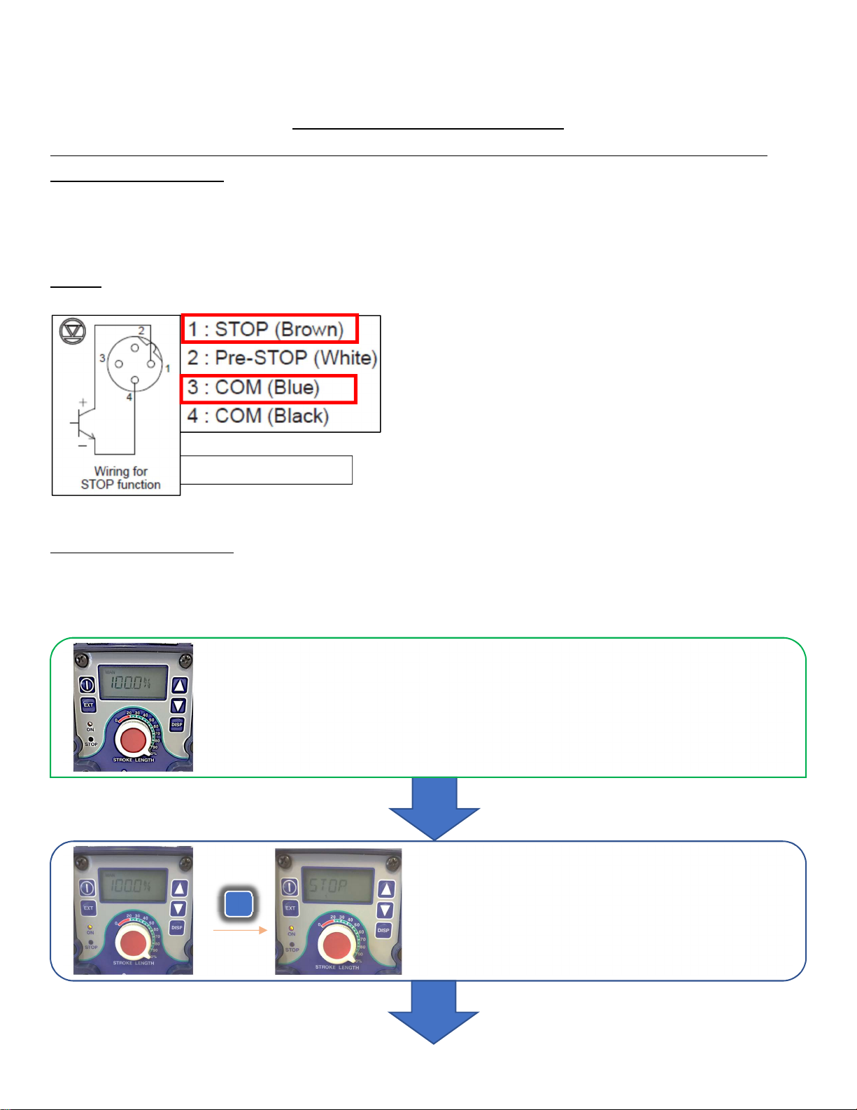
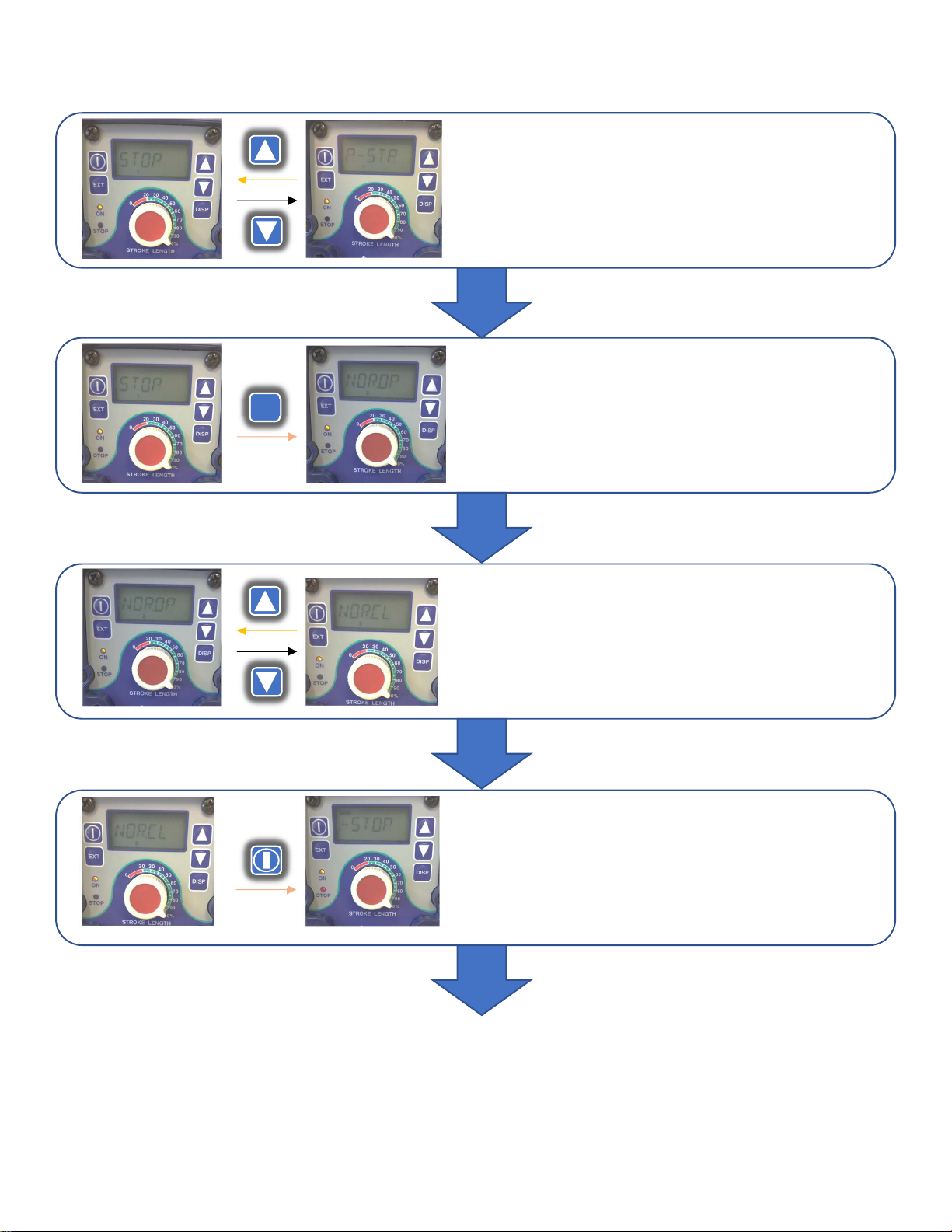
START/STOP – the chemical pump will Start or Stop after receiving a signal based on if the pump is set to be NO
(normally open) or NC (normally closed).
EXT MODE – the mode where the pump injects based off of an external signal. For Miura, this mode receives the pulse
signals from the CPI-MI or WP2.
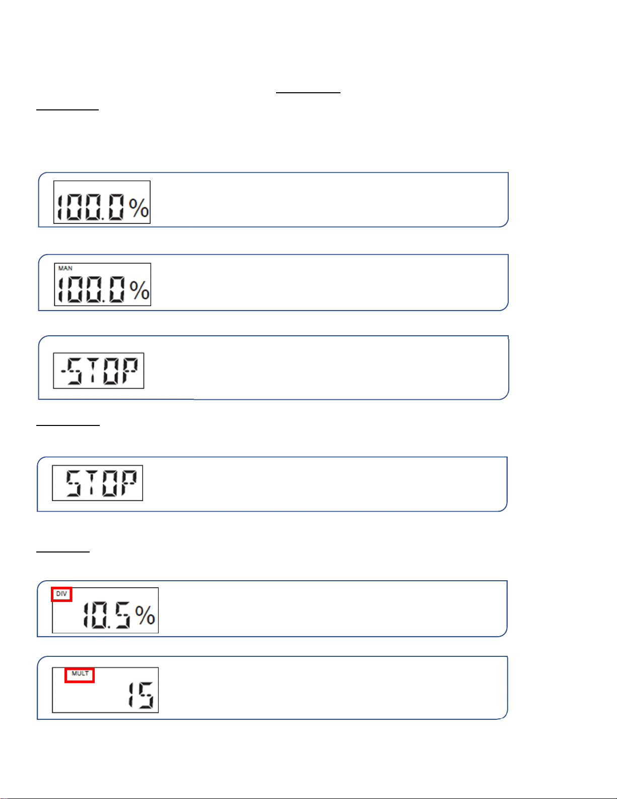
If the pump is set to EXT MULT, a [MULT] will show on the display.
The value on the display will depend on the set multiplier value.
The EWN-Y pump in WAIT MODE; the ON LED is ORANGE.
*100% is an example
While wired/set to START/STOP,
this will be displayed while the
pump is in WAIT MODE and is stopped. The ON LED will be Orange.
*It could be stopped due to receiving a signal or from not receiving
a signal, depending on if the pump is set to NO or NC.
The EWN-R pump in WAIT MODE; the ON LED is ORANGE.
*100% is an example
STOP is displayed when the pump has stopped, either by lack of
signal or due to a signal being received.
If the pump is set to EXT DIV, a [DIV] will show on the display. The
value on the display depends on the set dividing value.

5/3/2019 4
EWN-R CHEMICAL PUMPS
FOR USE WITHOUT WATER TREATMENT CONTROLLING SYSTEM (START/STOP) – Refer to
p.66 (EWN-R Manual)
The signal to run the Chemical Injection Pump is a START/STOP signal; normally it is the feed water pump contactor. The
chemical pump should be wired to inject when the feed water pump turns on. The chemical pump should have constant
power and should be powered, even when not injecting.
Wiring:
Using the pump cable CH00CTCABL00020, connect it to Connector 2 and the dry contactor.
Following the diagram, the brown wire should go to positive (+),
while the negative (-) is the black wire.
Pump Setup: Step-By-Step
When setting the chemical pump for START/STOP, it should be set to “NOR. CL” (normally closed), so that the chemical
pump injects when the feed water pump turns on.*
* NOR.OP is also an available setting. Please use the necessary pump setting according to the feed water contactor .
Refer to p. 60 of the EWN-R manual.
Feed Water Dry Contact
Have the pump in WAIT MODE
*Press the START/STOP button if the pump is running
to stop the pump.
Push and hold the EXT button for 3 seconds to go to
USER MODE.
EXT

5/3/2019 5
Select “STOP” (“STOP” should be displayed on the
screen).
Push the EXT button.
EXT
Select “NOR. CL” by pressing the UP or DOWN
button.
Push the START/STOP button to return to
WAIT MODE.

5/3/2019 6
Pump Setup: Flow Diagram
Press the START/STOP button again to remove the
pump from WAIT MODE, so that it can begin
injecting chemical.

5/3/2019 7
FOR USE WITH WP2 OR CPI-MI – Refer to p.55 (EWN-R Manual)
The signal to control the Chemical Injection Pump is a pulse signal which comes from the WP2 or CPI-MI. The chemical
pump will remain powered, but will only pump upon receiving pulses from the WP2 or CPI-MI. The rate at which the
pump injects chemical depends on the number of pulses. The chemical pumps must be in EXT (external) Mode in order
to respond to the digital pulses.
Wiring:
Using the pump cable CH00CTCABL00010, connect it to Connector 1 and the WP2 or CPI-MI.
CPI-MI Wiring
WP2 Wiring
The wires are wired into
the CPI
-
MI
at the terminals (P+) and (P-).
The wires are wired into IO
-
A at 25(+) &
26(-) or 26(-) & 27(+), or IO-B at 02(+) &
03(-) or 03(-) & 04(+) depending on
programing and number of pumps used.
Following the diagram, the white wire
should be positive (+), while the
yellow/green wire should be negative (-).

5/3/2019 8
Pump Setup: Step-By-Step
Select “MULT” by scrolling with the UP and
DOWN buttons.
Press the EXT button to set/confirm the
multiplier value.
EXT
Push and hold the EXT button for 3 seconds to go to
EXT MODE SELECTION.
EXT
Enter EXT MODE by pressing the EXT button while
the pump is in WAIT MODE. *Press the START/STOP
button if the pump is running to stop the pump.
EXT

5/3/2019 9
Pump Setup: Flow Diagram
Press the START/STOP button to return to EXT
MODE. It should now run when a pulse signal is
received from the CPI-MI.
*Green light shown above “ON”.
Confirm that the multiplier is (x 1). If it needs to be
changed, you can press the UP/DOWN buttons to
adjust the multiplier.
Press the EXT button to set/confirm the
multiplier value.
EXT

5/3/2019 10
EWN-Y CHEMICAL PUMPS
FOR USE WITHOUT CPI-MI (START/STOP) – Refer to p.26 (EWN-Y Manual)
The signal to run the Chemical Injection Pump is a START/STOP signal; normally it is the feed water pump contactor. The
chemical pump should be wired to inject when the feed water pump turns on. The chemical pump should have constant
power and should be powered, even when not injecting.
Wiring:
Using the pump cable CH00CTCABL00020, connect it to Connector 2 and the dry contactor.
Following the diagram, the brown wire should go to positive
(+), while the negative (-) is the black wire.
Pump Setup: Step-By-Step
When setting the chemical pump for START/STOP, the pump should be set to NC (normally closed), so that the chemical
pump injects when the feed water pump turns on.
* NO is also available. Please use the necessary pump setting according to the feed water contactor. Refer to p. 87-88 of
the EWN-Y manual.
Have the pump in WAIT MODE
*Press the START/STOP button if the pump is running
to stop the pump.
Press and hold the EXT button to go to
USER MODE.
1
sec.
EXT

5/3/2019 11
Press the UP/DOWN button to get to
INPUT setting.
Press the EXT button to go into the INPUT
settings menu.
EXT
Select STOP.L by pressing the UP/DOWN button.
Press EXT to select if the pump will be Normally
Open (NO) or Normally Closed (NC).
EXT

5/3/2019 12
Press the UP/DOWN button to select CL-OF.
*In this mode, the pump should run from
receiving an input.
Press the EXT button to return to STOP.L.
EXT
Press the START/STOP button to return to
USER MODE.
Press the START/STOP button to return to
WAIT MODE.

5/3/2019 13
Pump Setup: Flow Diagram
Press the START/STOP button to remove the
pump from WAIT MODE so that it can begin to
inject chemical.
*Green light shown above “ON” & Red light
shown above “STOP”.

5/3/2019 14
EWN-Y CHEMICAL PUMPS
FOR USE WITH WP2 or CPI-MI – Refer to p.75-76 (EWN-Y Manual)
The signal to control the Chemical Injection Pump is a pulse signal which comes from the WP2 or CPI-MI. The chemical
pump will remain powered, but will only pump upon receiving pulses from the WP2 or CPI-MI. The rate at which the
pump injects chemical depends on the number of pulses. The chemical pumps must be in EXT (external) Mode in order
to respond to the digital pulses.
Wiring:
Using the pump cable CH00CTCABL00010, connect it to Connector 1 and the WP2 or CPI-MI.
CPI-MI Wiring
WP2 Wiring
The wires are wired into
the CPI
-
MI
at the terminals (P+) and (P-).
The wires are wired into IO
-
A at 25(+) &
26(-) or 26(-) & 27(+), or IO-B at 02(+) &
03(-) or 03(-) & 04(+) depending on
programing and number of pumps used.
Following the diagram, th
e
brown
wire should be positive (+), while the
black wire should be negative (-).

5/3/2019 15
Pump Setup: Step-By-Step
Select “MULT” by scrolling with the UP and
DOWN buttons.
Press the EXT button to set/confirm the
multiplier value.
EXT
Press and hold the EXT button for 1 second to
go to EXT MODE.
1
sec.
EXT
Enter EXT MODE by pressing the EXT button while
the pump is in WAIT MODE.
*Press the START/STOP button if the pump is running
to stop the pump.
EXT

5/3/2019 16
Pump Setup: Flow Diagram
Press the START/STOP button to return to EXT
MODE. It should now run when a pulse signal is
received from the CPI-MI.
Confirm that the multiplier is (1). If it needs to be
changed, you can press the UP/DOWN buttons to
adjust the multiplier.
Press the EXT button to return to the EXT MODE
SELECTION display.
EXT

5/3/2019 17
EJ CHEMICAL PUMPS
FOR USE WITH WP2 or CPI-MI – Refer to p.43 (EJ Manual)
The signal to control the Chemical Injection Pump is a pulse signal which comes from the WP2 or CPI-MI. The chemical
pump will remain powered, but will only pump upon receiving pulses from the WP2 or CPI-MI. The rate at which the
pump injects chemical depends on the number of pulses. The chemical pumps must be in EXT (external) Mode in order
to respond to the digital pulses.
Wiring:
Using the pump cable CH00CTCABL00010, connect it to Connector 1 and the WP2 or CPI-MI.
CPI-MI Wiring
WP2 Wiring
The wires are wired into
the CPI
-
MI
at the terminals (P+) and (P-).
The wires are wired into IO
-
A at 25(+) &
26(-) or 26(-) & 27(+), or IO-B at 02(+) &
03(-) or 03(-) & 04(+) depending on
programing and number of pumps used.
Following the diagram, the brown
wire should be positive (+), while the
black wire should be negative (-).

5/3/2019 18
Pump Setup: Step-By-Step
Pump Setup: Flow Diagram
Have the pump in WAIT MODE
*Press the START/STOP button if the pump is running
to stop the pump.
Press START/STOP and UP and the spm
indication blink as the pump starts to run from
external pulse signals.
*The displayed spm shows an actual pump
speed in the EXT mode.
START
STOP

5/3/2019 19
Chemical Flow Checker (FCM)*
The Chemical Flow Checker is a device used to confirm the flow of chemical through the chemical pump.
When the chemical pump injects chemical, the Flow Checker will detect a pulse when chemical properly flows
through the pump. A [P] will also flash in the corner of the display every time the pump recognizes chemical
flow. If the pump does not sense flow, the [P] does not flash, and the pump will be set to react depending on
the number of “dry pumps”.
Refer to p. 31-34 for a description of the different Modes (A-D)
Installation:
Refer to p. 53-54 of the EWN-Y Manual
1) Remove the fitting and take out the
valve set from the pump head.
2) Place the valve set into the air vent body
B and tighten it into the pump head
through the Lock Nut.

5/3/2019 20
Wiring: WP2
3) Connect the Flow Checker body to the pump head
with the Lock Nut. Turn the Lock Nut counter-
clockwise to tighten them.
Note: Take care not to drop the plate, O-ring, or
float. The float also has a mounting direction; install
with the red mark facing upwards.
-
I/O-A
Discharge Rate Checker 1 (Flow Checker for pump 1): Red(17),
Black(18), White(19)
Discharge Rate Checker 2 (Flow Checker for pump 2): Red(17),
Black(18), White(20)
I/O-B
Discharge Rate Checker 3 (Flow Checker for pump 3): Red(12),
Black(11), White(10)
Discharge Rate Checker 4 (Flow Checker for pump 4): Red(12),
Black(1
1
), White(
09
)
This manual suits for next models
2
Table of contents
Other IWAKI WALCHEM Water Pump manuals
Popular Water Pump manuals by other brands

Franklin Electric
Franklin Electric Little Giant VCMA Series owner's manual

GORMAN-RUPP
GORMAN-RUPP SFDV3A Installation, operation, and maintenance manual with parts list

Reefe
Reefe 22597 Exploded View & Instruction Manual

Lowara
Lowara TLC SERIES operating manual

Speck pumpen
Speck pumpen BADU Spyder I operating instructions

RICE HYDRO
RICE HYDRO TRH-2 operating instructions