iWave iW-PRDLT-AP-01-R2.0-51 User manual

iWave GPS Module User Manual
REL1.9
iWave Systems Technologies Pvt. Ltd. Page 4 of 29
(Confidential)
Table of Contents
1TECHNICAL SPECIFICATIONS...................................................................................7
2IWAVE GPS MODULE....................................................................................................9
3IWAVE GPS MODULE INTERFACE..........................................................................10
3.1 IWAVE GPS MODULE IO CONNECTOR.........................................................................10
3.2 ANTENNA INTERFACE DETAILS TO IWAVE GPS MODULE..............................................10
4APPLICATION CIRCUIT.............................................................................................11
5MECHANICAL DIMENSION.......................................................................................12
6NMEA PROTOCOL.......................................................................................................14
6.1 GENERAL FORMAT .....................................................................................................14
6.2 GGA —GLOBAL POSITIONING SYSTEM FIXED DATA...................................................15
6.3 GLL—GEOGRAPHIC POSITION -LATITUDE/LONGITUDE..............................................16
6.4 GSA—GNSS DOP AND ACTIVE SATELLITES .............................................................17
6.5 GSV—GNSS SATELLITES IN VIEW ............................................................................18
6.6 RMC—RECOMMENDED MINIMUM SPECIFIC GNSS DATA...........................................19
6.7 VTG—COURSE OVER GROUND AND GROUND SPEED..................................................20
6.8 ZDA—TIME &DATE .................................................................................................21
7PCB DESIGN GUIDELINES .........................................................................................22
8ANNEXURE....................................................................................................................23

iWave GPS Module User Manual
REL1.9
iWave Systems Technologies Pvt. Ltd. Page 5 of 29
(Confidential)
List of Figures
FIGURE 1: IWAVE GPS MODULE R2.0..........................................................................................9
FIGURE 2: APPLICATION CIRCUIT................................................................................................11
FIGURE 3: GPS MODULE PCB DIMENSION (TOP VIEW)................................................................12
FIGURE 4: GPS MODULE PCB DIMENSION WITH SHIELDING SLOT.................................................13

iWave GPS Module User Manual
REL1.9
iWave Systems Technologies Pvt. Ltd. Page 6 of 29
(Confidential)
List of Tables
TABLE 1: IWAVE GPS MODULE SPECIFICATION ............................................................................7
TABLE 2: IO CONNECTOR PIN DETAILS.......................................................................................10
TABLE 3: NMEA MESSAGE........................................................................................................14
TABLE 4: GGA DATA FORMAT....................................................................................................15
TABLE 5: GLL DATA FORMAT.....................................................................................................16
TABLE 6: GSA DATA FORMAT ....................................................................................................17
TABLE 7: GSV DATA FORMAT ....................................................................................................18
TABLE 8: RMC DATA FORMAT ...................................................................................................19
TABLE 9: VTG DATA FORMAT....................................................................................................20
TABLE 10: ZDADATA FORMAT..................................................................................................21
TABLE 11: NMEA INPUT MESSAGES..........................................................................................23
TABLE 12:TRANSPORT MESSAGE PARAMETERS...........................................................................23
TABLE 13: SET SERIAL PORT DATA FORMAT ..............................................................................25
TABLE 14: NAVIGATION INITIALIZATION DATA FORMAT.............................................................26
TABLE 15: RESET CONFIGURATION -NON SIRFLOC PLATFORMS ................................................26
TABLE 16: QUERY/RATE CONTROL DATA FORMAT.....................................................................27
TABLE 17: LLANAVIGATION INITIALIZATION DATA FORMAT ....................................................28
TABLE 18: RESET CONFIGURATION.............................................................................................28

iWave GPS Module User Manual
REL1.9
iWave Systems Technologies Pvt. Ltd. Page 7 of 29
(Confidential)
1Technical Specifications
Table 1: iWave GPS module Specification
Feature Item Description
Chipset SiRF StarIII GSC3f/LPx-7989
Processor Info Processor Type ARM7TDMI CPU
Processor Speed 50 MHz
Data Bus 16 Bit Bus access for internal Flash only
Internal Flash 4Mb
Internal RAM 1Mb
General Frequency L1 Frequency (1575.42MHz)
Channels 20 (Max)
GPS receiver function Position Autonomous: 10 meter (Open Sky)
Time 1 microsecond synchronized to GPS time
Maximum Altitude 18000 meter
Maximum Speed 514 meter/second maximum
Software GPS Datum
(GPS coordinate systems) WGS-84
Protocol NMEA
Output Protocol message GGA,GSA,GSV,RMC,VTG
Baud Rate 9600
Max.Update Rate 1Hz
Time To First Fix
(Open Sky and
Stationary Requirement) Reacquisition 1.0 Sec
Hot Start <2 sec average
Cold Start < 41 sec average
Sensitivity Chip Sensitivity -159dBm

iWave GPS Module User Manual
REL1.9
iWave Systems Technologies Pvt. Ltd. Page 8 of 29
(Confidential)
Power Main Power Input 3.3V
Power Consumption 132mW
Supply Current (Avg.) 40mA
Backup Power 3.0V
Serial Port (UART
CMOS) Port A (TX and RX only) NMEA Protocol message
Antenna Antenna Type Active Antenna supported SMA
connector provided for Antenna interface.
Environmental
Characteristics Operating Temperature -25 deg. C to +80 deg.C
Storage Temperature -25 deg. C to +85 deg.C
Physical Characteristics Length 27mm
Width 25mm
Height 11.67mm (Including SMA Connector)
Weight <25 grams
IO connector 6 Pin Battery backup (3V)
3.3V Main Power Input
Ground (DC-ve)
UARTA TX Output from Module (2.85V
Output , 3.3V tolerant)
UARTA RX Input to Module (2.85V
Input , 3.3V tolerant)
1 GPIO to IO connector (No connect)

iWave GPS Module User Manual
REL1.9
iWave Systems Technologies Pvt. Ltd. Page 9 of 29
(Confidential)
2iWave GPS Module
iWave GPS Module top view.
Figure 1: iWave GPS Module R2.0
IWave GPS module bare PCB size is 23mmX 27mm, after assembling components the size is
25mm X 27mm because of IO connector.
IWave GPS module can be directly connected to external Active GPS antenna using SMA
connector as shown in Figure 1.

iWave GPS Module User Manual
REL1.9
iWave Systems Technologies Pvt. Ltd. Page 10 of 29
(Confidential)
3iWave GPS Module Interface
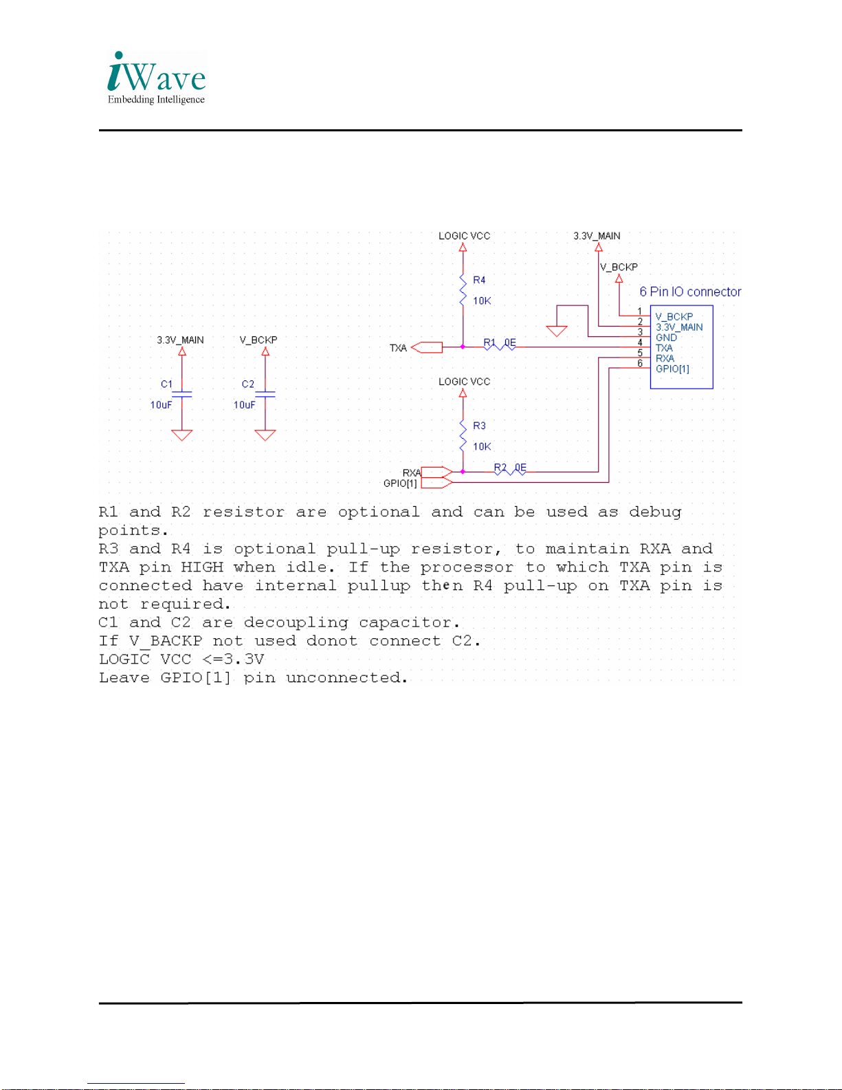
3.1 iWave GPS module IO Connector
The IO connector is a Single Row 1.25mm pitch Miniature Crimping type Connector
from Protectron. It is a Right Angle Pin Header (TH): P9056R29-19-6 which can be mated with
Single Row 1.25mm pitch Receptacle Housing: P9056H29-00-6.Crimp Terminal for 1.25mm
pitch Housing: P9056T00-19
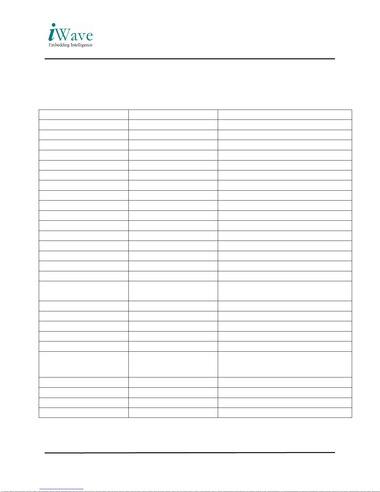
The pin details are provided in the table given below.
Pin No
Pin Name Description Characteristics
1 VBCKP RTC Backup Battery Input
(Input) Nominal: DC 3.0 V
Range: DC 2.5V to 3.6V Max.
2 3.3V Main
Main power supply for the module
(Input) Nominal: DC 3.3V
Range: DC 3.1V to 3.6V Max.
3 Ground Ground Reference Ground (DC -ve)
4 TXA Transmit pin of the module
(Output) 2.85V Interface
VOH: 2.65V(min)
VOL: 0.2V(max)
5 RXA Receive pin of the module
(Input) 2.85V Interface (3.3V Tolerant)
VIH: 2V(min) to 3.15V(max)
VIL: -0.3V(min) to 0.8V(max)
6 GPIO GPIO Line (No Connection)
Table 2: IO Connector Pin Details
3.2 Antenna interface details to iWave GPS module
Only Active Antenna support is provided, 2.85V is provided to external connector.
Gain of the Antenna tested is approximately 28 +/- 2 dB.
Recommended LNA gain of the active antenna is 16dB < 28dB
Better to have noise figure < 2dB.
External antenna should work with 2.85V.
SMA connector is used to interface external Active antenna to iWave GPS Module.

iWave GPS Module User Manual
REL1.9
iWave Systems Technologies Pvt. Ltd. Page 11 of 29
(Confidential)
4Application Circuit
Figure 2: Application circuit

iWave GPS Module User Manual
REL1.9
iWave Systems Technologies Pvt. Ltd. Page 12 of 29
(Confidential)
5Mechanical dimension
iWave GPS module PCB dimension
Figure 3: GPS module PCB dimension (Top View)

iWave GPS Module User Manual
REL1.9
iWave Systems Technologies Pvt. Ltd. Page 13 of 29
(Confidential)
iWave GPS module PCB dimension
Figure 4: GPS module PCB dimension with shielding slot

iWave GPS Module User Manual
REL1.9
iWave Systems Technologies Pvt. Ltd. Page 14 of 29
(Confidential)
6NMEA Protocol
SiRF products support a subset of the NMEA-0183 standard
6.1 General Format
NMEA 0183 messages use the ASCII character set and have a defined format. Each message
begins with a $ (hex 0x24) and end with a carriage return and line feed (hex 0x0D 0x0A,
represented as <CR><LF>). Each message consists of one or more fields of ASCII letters and
numbers, separated by commas. After the last field, and before the <CR><LF> can be an
optional checksum consisting of an asterisk (*, hex 0x2A) followed by two ASCII characters
representing the hexadecimal value of the checksum. The checksum is computed as the exclusive
OR of all characters between the $ and * characters.
Message Description
GGA Time, position and fix type data
GLL Latitude, longitude, UTC time of position fix and status
GSA GPS receiver operating mode, satellites used in the position solution,
and DOP values
GSV Number of GPS satellites in view satellite ID numbers, elevation,
azimuth, & SNR values
RMC Time, date, position, course and speed data
VTG Course and speed information relative to the ground
ZDA PPS timing message (synchronized to PPS)
Table 3: NMEA Message

iWave GPS Module User Manual
REL1.9
iWave Systems Technologies Pvt. Ltd. Page 15 of 29
(Confidential)
6.2 GGA —Global Positioning System Fixed Data
Note – Fields marked in italic red apply only to NMEA version 2.3 (and later) in this NMEA
message description.
Table 4 contains the values for the following example:
$GPGGA,002153.000,3342.6618,N,11751.3858,W,1,10,1.2,27.0,M,-34.2,M,,0000*5E
GGA data format
Position fix indicator
Table 4: GGA data format

iWave GPS Module User Manual
REL1.9
iWave Systems Technologies Pvt. Ltd. Page 16 of 29
(Confidential)
6.3 GLL—Geographic Position - Latitude/Longitude
Table 5 contains the values for the following example:
$GPGLL,3723.2475,N,12158.3416,W,161229.487,A,A*41
GLL data format
Table 5: GLL data format

iWave GPS Module User Manual
REL1.9
iWave Systems Technologies Pvt. Ltd. Page 17 of 29
(Confidential)
6.4 GSA—GNSS DOP and Active Satellites
Table 6 contains the values for the following example:
$GPGSA,A,3,07,02,26,27,09,04,15, , , , , ,1.8,1.0,1.5*33
GSA data format
Table 6: GSA data format

iWave GPS Module User Manual
REL1.9
iWave Systems Technologies Pvt. Ltd. Page 18 of 29
(Confidential)
6.5 GSV—GNSS Satellites in View
Table 7 contains the values for the following example:
$GPGSV,2,1,07,07,79,048,42,02,51,062,43,26,36,256,42,27,27,138,42*71
$GPGSV,2,2,07,09,23,313,42,04,19,159,41,15,12,041,42*41
GSV data format
Table 7: GSV data format

iWave GPS Module User Manual
REL1.9
iWave Systems Technologies Pvt. Ltd. Page 19 of 29
(Confidential)
6.6 RMC—Recommended Minimum Specific GNSS Data
Table 8 contains the values for the following example:
$GPRMC,161229.487,A,3723.2475,N,12158.3416,W,0.13,309.62,120598, ,*10
RMC data format
Table 8: RMC data format

iWave GPS Module User Manual
REL1.9
iWave Systems Technologies Pvt. Ltd. Page 20 of 29
(Confidential)
6.7 VTG—Course Over Ground and Ground Speed
Table 9 contains the values for the following example:
$GPVTG,309.62,T, ,M,0.13,N,0.2,K,A*23
VTG data format
Table 9: VTG data format

iWave GPS Module User Manual
REL1.9
iWave Systems Technologies Pvt. Ltd. Page 21 of 29
(Confidential)
6.8 ZDA—Time & Date
Table 10 contains the values for the following example:
$GPZDA,181813,14,10,2003,,*4F
ZDA data format
Table 10: ZDA data format

iWave GPS Module User Manual
REL1.9
iWave Systems Technologies Pvt. Ltd. Page 22 of 29
(Confidential)
7PCB Design Guidelines
•Avoid routing high frequency signals on the top layer of the customer PCB, just below
GPS module.
•Better to provide ground shape on the top layer of customer PCB, just below GPS
module.
•Do not provide any open mask on top layer of customer PCB, just below GPS module.
•RF shielding on GPS module is connected to ground (-Ve DC), please take care when
fixing the GPS module to customer PCB.

iWave GPS Module User Manual
REL1.9
iWave Systems Technologies Pvt. Ltd. Page 23 of 29
(Confidential)
8Annexure
NMEA Input Message:
The below table lists out the NMEA Input Messages
Message MID1Description
Set Serial Port 100 Set PORT A parameters and protocol
Navigation Initialization 101 Parameters required for start using X/Y/Z.2
Set DGPS Port 102 Set PORT B parameters for DGPS input
Query/Rate Control 103 Query standard NMEA message and/or set output
rate
LLA Navigation Initialization 104 Parameters required for start using Lat/Lon/Alt.3
Development Data On/Off 105 Development Data messages On/Off
Select Datum 106 Selection of datum to be used for coordinate
transformations
MSK Receiver Interface MSK Command message to a MSK radio-beacon
receiver.
Table 11: NMEA Input Messages
1. Message Identification (MID)
2. .Input coordinates must be
3. WGS84.Input coordinates must be WGS84.
Transport Message
Start Sequence Payload checksum End Sequence
$PSRF<MID>1Data2Checksum3End Sequence4
Table 12:Transport Message parameters
1. Message Identifier consisting of three numeric characters. Input messages begin at MID
100.
2. Message specific data. Refer to a specific message section for <data>...<data> definition.
Table of contents
Popular GPS manuals by other brands

Btwin
Btwin ANT+ SAT COUNT manual

US Fleet Tracking
US Fleet Tracking USFT VT-X5 install guide

Blackbe;rry
Blackbe;rry Radar H2 installation guide

ZL electronics Technology
ZL electronics Technology 900G user manual

Raymarine
Raymarine E90W User reference handbook

CSI Wireless
CSI Wireless Seres Reference manual