Jackel JP250V User manual

/ JP233V

GENERAL INFORMATION
To ensure safe and reliable operation, please carefully read this service and installation manual in its entirety before
installing and / or using this product. Reasonable care and safe methods in according with sound plumbing practices
should be strictly adhered to. Before installation, refer to and understand all relevant local plumbing and electrical codes.
DO NOT THROW AWAY THIS MANUAL. Keep it in a safe place so that you may refer to it for periodic service and
maintenance.
Always disconnect the power before servicing this product. Failure to do so may result in
serious injury or death. Consult with a qualied electrician if you are unsure of the power
source or cannot determine whether power has been properly disconnected
• Risk of electric Shock. Always disconnect power before servicing the pump.
• Electrical Connections and wiring for a pump installation should only be made by qualied personnel.
• This equipment is only for use on 115 volt and is equipped with an approved 3-conductor cord and 3-prong,
grounding-type plug. To reduce the risk of electric shock, be certain that it is connected to a properly grounded,
grounding type receptacle.
• DO NOT bypass grounding wires or remove the ground prong from the plug.
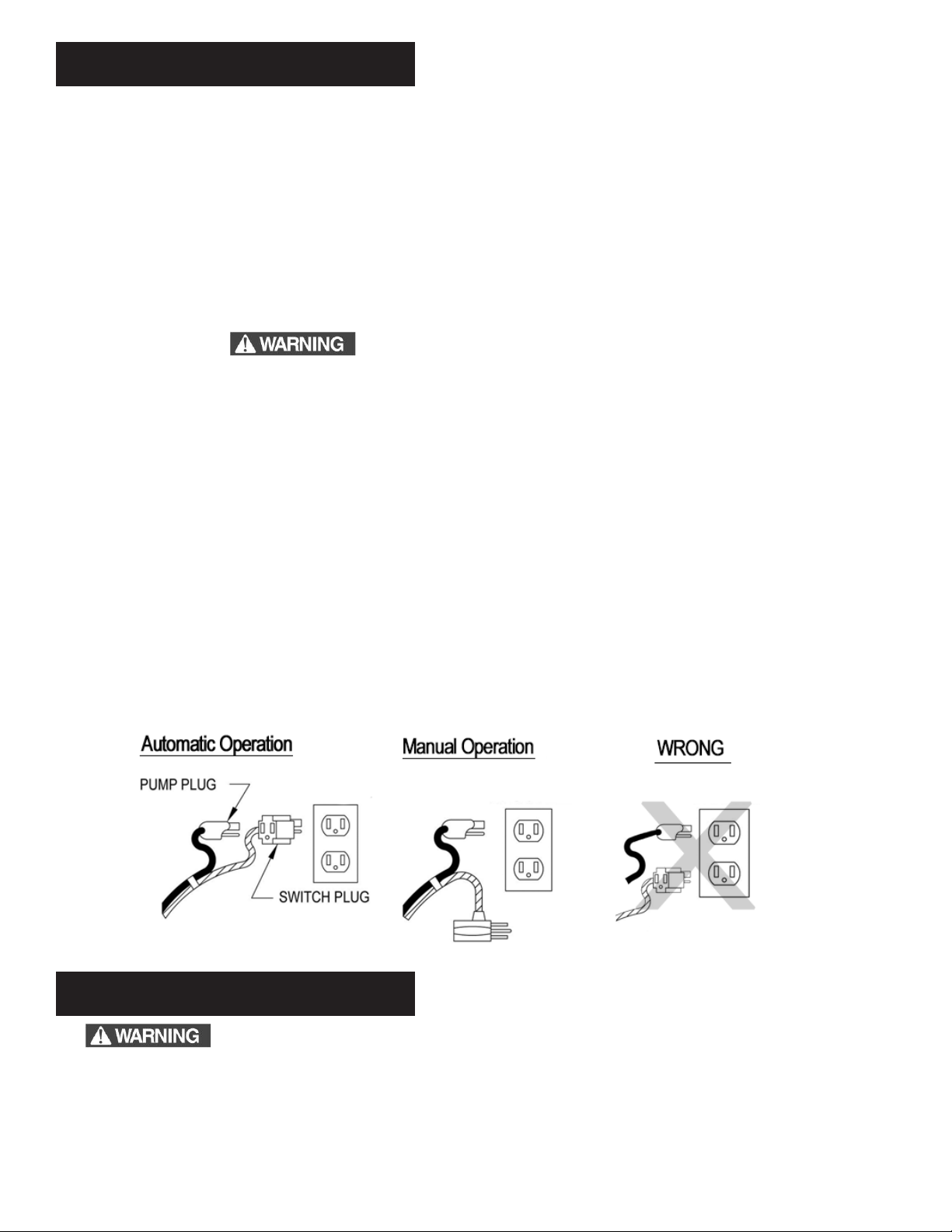
• DO NOT use an extension cord.
• NEVER plug this pump into an outlet while standing on a wet surface.
• NEVER lift this product by the electrical power cord.
• NEVER attempt to open or service this pump while it is connected to an electrical power supply.
• DO NOT pump gasoline or any ammable liquid with this pump. Explosion, re or serious injury or death may
result from pumping gasoline or any ammable liquid with this product.
• DO NOT pump chemicals or corrosive liquids with this pump
• To reduce risk of electircal shock, fully read and understand the operating and installation instructions
accompanying this pump BEFORE attempting to install or operate this pump.
• Know the pump application, limitations, and potential hazards.
• Release all pressure within system before servicing any component.
• Drain all water from system before servicing.
• Secure discharge line before starting pump. An unsecured discharge line will whip, possibly causing personal
injury and/or property damage.
• Check hoses for weak or worn condition before each use, making certain that all connections are secure.
• Periodically inspect sump, pump and system components.
• Keep free of debris and foreign objects. Perform routine maintenance as required.
• Provide means of pressure relief for pumps whose discharge line can be shut-off or obstructed.
Personal Safety:
• Wear safety glasses at all times when working with pumps.
• Keep work area clean, uncluttered and properly lighted – replace all unused tools and equipment.
• Keep visitors at a safe distance from work area.
• Make workshop child-proof – with padlocks, master switches, and by removing starter keys.
• When wiring an electrically driven pump, follow all electrical and safety codes that apply.
• DO NOT use this pump in water over 150° F
• DO NOT modify the pump in any way.
• DO NOT remove any tags from the pump or the electrical cords. Removal of these tags may void your warranty.
SAFETY INFORMATION

INSTALLATION
The minimum sump pit diameter recommended is 10” with a minimum depth of the pit of at least 12” above the surface
that the pump is resting on.
If the pit is not already enclosed on the bottom, provide a hard level bottom of bricks or concrete. DO NOT place the pump
directly on earth, gravel or debris since this can cause excessive wear of the impeller and possible jamming. Remove all
debris from the bottom of the sump pit before installation of the pump. A sump pit cover is suggested for safety and to
prevent foreign objects from entering the pit.
1. Remove Old Pump. Disconnect pump from power source before handling.
2. Separate the discharge pipe at either the check valve or at the union. If neither a check valve nor a union is part of the
existing discharge pipe, cut the pipe with a hacksaw and remove the pump.
3. Set the new pump in place making sure the oat switch has adequate clearance and will not hang-up on the pit wall. The
oat must be free to move throughout its travel and not contacting the pump body, piping, or other objects.
4. A 1-1/2” threaded discharge is provided on the pump for connection to the discharge pipe. Do not reduce the discharge
size to less than 1-1/4”, as this will affect pump ow and performance. Schedule 40 PVC pipe is recommended; however,
exible discharge hose kits may be used for temporary installations.
5. Connect the pipe or the discharge hose to the discharge of the pump.
6. Install a union or other means of separating the discharge pipe just above the oor to facilitate removal of the pump if
necessary. A check valve is required and can be installed in place of a union to prevent the backow of water after each
pump cycle.
7. Connect additional pipe as necessary to direct the discharge to the desired location. Discharge should be kept as short
as possible with a minimum number of turns. Check all connections.
8. This pump comes factory-equipped with a oat switch that has two cords - one to the oat switch and the other to the
pump motor. The switch cord has a series (piggyback) plug enabling the pump (motor) cord to be plugged into the back
of it (see Figure below). The purpose of this design is to allow temporary manual operation of the pump if desired.
TROUBLE-SHOOTING
Always disconnect the pump from power source before handling. This guide is designed to help
identify reasons for potential operating problems. It is not a service guide. Dismantling of pump voids warranty.
Servicing of pump other than simple cleaning of pump inlet or impeller should be referred to the factory or its
authorized service centers.
NOTE: The manufacturer assumes no responsibility for injury or damage associated with disassembly or
modication of the pump. Consult with customer service before attempting any disassembly.
NOTE: MAXIMUM LIFT MODEL: JP233V is 22’
MODEL: JP250V is 25’

TROUBLE-SHOOTING (CONTINUED)
PUMP DOES NOT RUN OR HUMS.
1. Line circuit breaker may be off, tripped or loose. Have certied electrician check fuse or breaker.
2. Water level in pit may be too low to activate switch. Add more water to pit.
3. Plug on power cord may not be making contact in receptacle. Check security and connection.
4. If the pump is using the series (piggyback) cord plug, the plugs may not be connected tightly together.
5. Float may be obstructed. Make sure oat is free and not interfering with the pit wall or other obstruction.
6. If all symptoms check OK, the motor winding may be open. Consult factory.
PUMP RUNS OR HUMS BUT DOES NOT DELIVER WATER.
1. Check valve may be installed backwards or is defective. Check to make sure it is installed properly and apper in
valve is free to move.
2. Discharge line may be blocked or frozen. Check to see if line passes through cold areas or is blocked.
3. Vertical lift may be beyond pumps capability. See chart below for your pump’s maximum lift capability.
NOTE: At the pump’s maximum lift there will be no ow.
4. Check to see if inlet screen of pump is plugged or the impeller is jammed. Clean inlet and impeller as needed.
5. Pump Impeller may be jammed. Check for foreign material such as construction debris, stones, etc. that might be
preventing the impeller from rotating. Reminder: Make sure pump is disconnected from power source before checking
inlet and impeller area.
PUMP RUNS AND REMOVES WATER BUT DOES NOT SHUT OFF.
1. Float is stuck in the “on” position. Check to make sure the oat is free to move up and down without obstruction.
2. Switch may be defective. Consult factory.
PUMP RUNS BUT DELIVERS VERY LITTLE WATER.
1. Vertical lift is approaching the pump’s maximum lift capability. Refer to the above maximum lift chart.
2. Pump’s inlet is partially blocked. Check to make sure the inlet is clear of debris.
3. Discharge line is partially blocked. Check line for blockage.
4. Check valve is not opening all the way. Check for defective, reversed, or blocked check valve.
CIRCUIT BREAKER TRIPS OR FUSE BLOWS WHEN PUMP STARTS.
1. Fuse or breaker size is too small.
2. Other major appliances are on the same circuit. Pump should be on its own circuit.
3. Pump is connected to an extension cord or wiring is inadequate. Have an electrician check for proper wiring.
4. Motor or switch may be defective. Consult factory.
PUMP CYCLES TOO OFTEN OR RUNS CONSTANTLY
1. Check Valve may have failed causing discharged water to return to the sump pit. Cycle pump and look for water
rushing back through the pump inlet. Replace Check Valve as necessary.
2. Pump May be sized incorrectly. Check with your local plumber for recommendation.
3. Pump Inlet may be blocked. Unplug pump from power source and clean inlet.

MAINTENANCE
These Submersible pump models have sealed permanently lubricated bearings and require no additional lubrication.
The pump should be checked frequently for debris and/or build up which may interfere with pump or oat switch operation.
The oat must be able to move freely through its complete travel without any restrictions. Pour enough water into the
sump to activate the pump periodically (at least every 3 months) when not normally in use to verify proper function. Check
periodically to make sure the pit is free from accumulated debris, rocks or other objects that may potentially jam the pump
Installation of a Battery Backup Sump Pump System is highly recommended as a backup to your pump in the case of
power failure of pump failure. Minimally, a high water alarm should be installed.
The Sump Pump Check Valve is a critical component in ensuring a reliable pumping system for years to come. However,
Check Valves have a limited life. We strongly recommend that you replace the check valve at least once a year.
If you live in a cold climate where temperature routinely below freezing, make sure that your discharge line is protected
against ice blockage. We strongly recommend that a Freeze Drain be installed outside on your discharge line to prevent
blockage in your sump pump discharge line.
FOR YOUR RECORDS
Date of Purchase
Place of Purchase
Serial Number
ATTACH RECEIPT HERE
Installed by:
Model Number
Note:
You MUST retain your original purchase receipt along with this manual. In
the event that you need to exercise a warranty claim, you MUST send a
copy of the purchase receipt along with the material or correspondence.

87083-01
LIMITED WARRANTY GUIDE CHEC
This Limited Warranty applies to model JP233V and JP250V residential sump pumps sold under only the Jackel
brand.
Jackel warrants to the original consumer purchaser (“Purchaser” or “You”) of Jackel pumps that they will be free from
defects in material and workmanship for the Warranty Period of 84 months from date of purchase. The date of
purchase shall be determined by the original dated sales receipt noting the model and serial number of the pump.
The original sales receipt must accompany the returned pump.
Jackel shall not be liable under this Warranty for any product that, in our sole judgment, has been subject to
negligence, misapplication, improper installation, or improper maintenance. Also, Jackel shall not be liable under this
Warranty if the product has been disassembled, modified, abused or tampered with; if the electrical cord has been
cut, damaged or spliced; if the pump discharge has been reduced in size; if the pump has been used in water
temperatures above the advertised rating, or water containing sand, lime, cement, gravel or other abrasives; if the
product has been used to pump chemicals or hydrocarbons; or if the label bearing the pump model and serial
numbers has been removed.
Your sole remedy and Jackel’s only duty is that Jackel repair or replace defective pump (at Jackel’s choice). You
must pay all labor and shipping charges associated with this warranty and must request warranty service through the
installing dealer as soon as the problem is discovered. No request for service will be accepted if received after the
Warranty Period has expired. This warranty is non-transferable.
Jackel shall not be liable for any consequential, incidental, or contingent damages whatsoever. Jackel
recommends using a professional plumber for all installation and repair and periodic inspection of Jackel
pumps. Jackel makes no warranty regarding the suitability of a product for a particular installation.
Purchasers are responsible for determining whether a pump is suitable for a specific application.
This warranty excludes all industrial, agricultural, commercial and business usage of Jackel pumps.
The foregoing warranties are exclusive and in lieu of all other express and implied warranties, including but
not limited to the implied warranties of merchantability and fitness for a particular purpose. The foregoing
warranties shall not extend beyond the duration expressly provided herein.
Some states do not allow the exclusion or limitation of incidental or consequential damages or limitations on the
duration of the implied warranty, so the above limitations or exclusions may not apply to you. This warranty gives
you specific legal rights and you may also have other rights, which may vary from state to state. This warranty
applies to only Jackel pumps installed in the United States of America and Canada.
This warranty supersedes and replaces all previous warranty publications.
Jackel, Inc.
15314 Harrison Road - Mishawaka, IN 46544
574-256-5635 – www.Jackelinc.com
87083-01
This manual suits for next models
1
Table of contents
Popular Water Pump manuals by other brands

Franklin Electric
Franklin Electric VR Series owner's manual

Total
Total TWP47501 quick start guide

DIPRA
DIPRA SPID'O JCA-800P2 Original operating instructions

Pentair
Pentair INTELLIFLO VSD2 quick start guide

ITT
ITT LSN Installation, operation and maintenance instructions

BUSCH
BUSCH RA 0025 F instruction manual