Jagg 751-FP2500 User manual

1
IMPORTANT INFORMATION
This Jagg oil cooler must be installed following these instructions. Read the easy-to-follow instructions fully prior to starting
the installation of the oil cooler kit. Correct installation is the only way to ensure proper operation of the oil cooler kit.
BASIC SYSTEM INSTALLATION GUIDELINES
INSTALLATION INSTRUCTIONS
• Route oil hose to avoid any hot surfaces or moving
parts. Ensure all bends are smooth, with no sharp turns
that may restrict oil supply to the engine.
• Oil cooler is designed to mount as detailed in these
instructions. Any modications may lead to decreased
performance or item failure.
• When cutting oil hoses, always use a sharp knife, sin-
gle-edge razor blade, or hose cutter. Make a straight,
clean cut at 90º to the oil hose. This will ensure a prop-
er t where the oil hose attaches to its connection.
• Over tightening hose clamps may cause oil leaks.
QTY. KIT CONTENTS
1 Jagg FP2500 Fan-assisted oil cooler assy.
1Jagg 4700 offset oil lter adapter assembly
2 ft Jagg 30R7spec black oil hose
4 7/8” black worm-drive hose clamps
1 Jagg anti-rotation device
2 Bolts: 10-24 x 1-3/8” cap head, black
1Stock-to-Jagg oil lter nipple
1 Jagg automatic fan switch, 190ºF
1Street-tee pipe tting, NPT1/8 male to
2xNPT1/8 female
45” Wiring harness for WeatherTek fan
45” Convoluted wire cover
3 Plastic zip-ties
CAUTION: ALLOW MOTORCYCLE TO COOL BEFORE ATTEMPTING INSTALLATION OR RISK SERIOUS INJURY.
TOOLS NEEDED
Strap wrench or oil lter removal tool 5/32” Allen wrench
Phillips head screwdriver 7/16” Allen wrench (if removing a stock H-D oil cooler)
7/8” socket Hose cutter or sharp knife
1” deep-well socket Teon pipe sealant (e.g., Loctite 592)
7/16” deep-well socket Dielectric grease
Needle-nose pliers
Part # 751-FP2500

2
Oil cooler plumbing
The Jagg offset oil lter adapter is used to ac-
cess the oil supply for the installation of a Jagg oil
cooler. The adapter features a built-in automatic
thermostat to allow oil to by-pass the oil cooler,
simply being ltered and returned to the engine,
until the bike warms up to operating temperature.
Once the bike reaches operating temperature,
the thermostat will close the adapter’s by-pass
hole, sending hot, ltered oil to the oil cooler, and
delivering cool, clean oil to the engine.
Part 1: Installing the offset oil lter adapter
1. Remove spin-on oil lter, and clean the lter
mounting surface thoroughly.
2. If removing and upgrading a factory Har-
ley-Davidson oil cooling system, uninstall the
stock oil lter adapter by removing the anged
oil lter nipple that holds the adapter in place
using a 7/16” Allen wrench. Locate the stock-
to-Jagg oil lter nipple (shown
at right) included in the kit.
Install by inserting the or-
ange-painted end into the port
where the stock oil lter stem
was removed. Using a 7/8”
socket, tighten until the hex is
ush against the oil lter hous-
ing.
3. Disassemble the Jagg offset oil lter adapter
by removing the ve Allen head bolts from
the front face of the adapter using a 5/32”
Allen wrench. Then remove the front half of
the adapter (the portion with hose ttings
attached).
4. With the longer/offset end of the adapter at
the top, place the back half of the adapter (the
portion with the at rubber o-ring) over the
threaded oil lter stem and tighten the includ-
ed 1” lock-nut to nger-tight. The adapter’s at
sealing rubber o-ring should face in, toward
the stock oil lter housing, and be free of de-
bris. (Do not apply oil to this o-ring.)
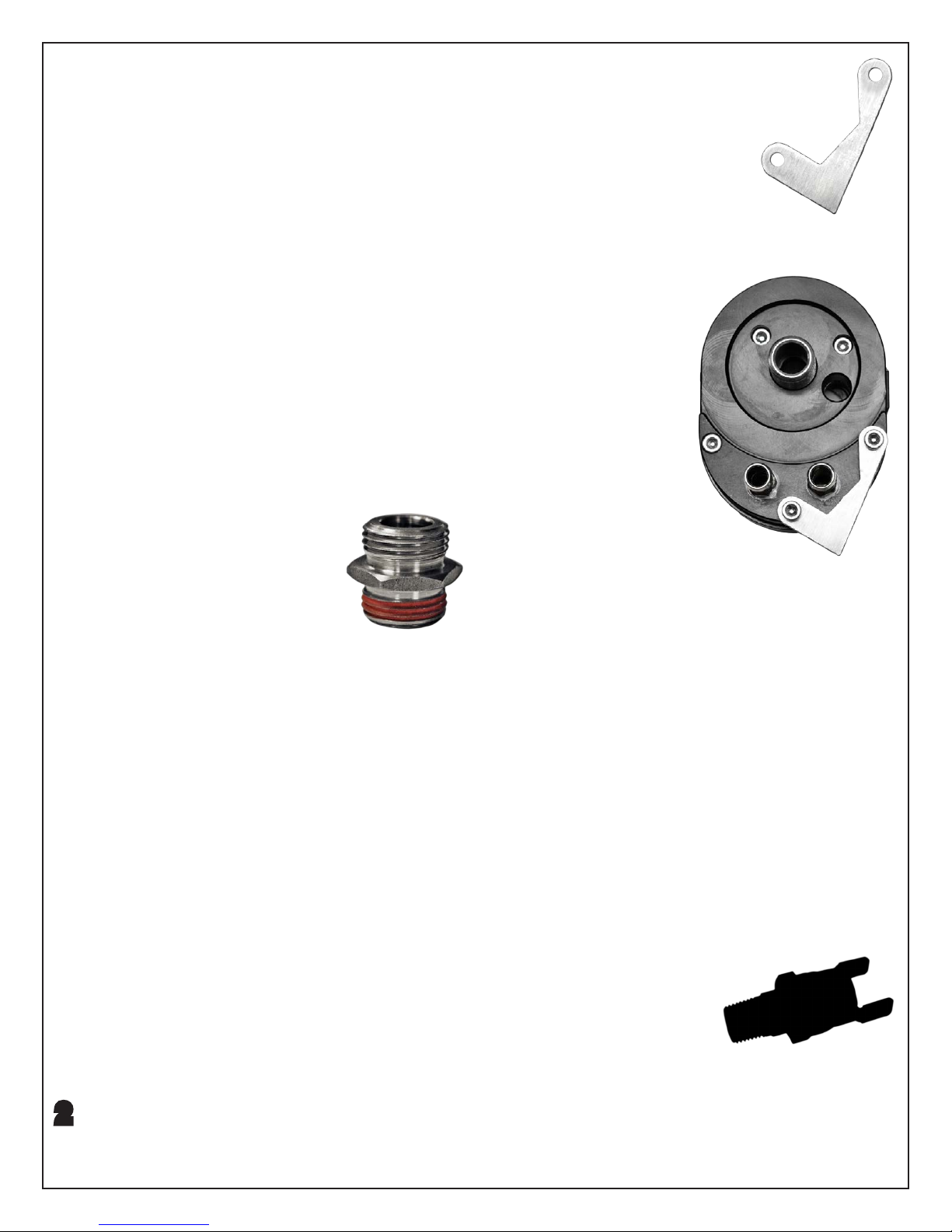
5. Locate part 4600AR-C Jagg anti-rotation
device. Installation of this device will ensure
the Jagg 4700 offset oil lter adapter will not
rotate during oil lter removal.
6. Place the anti-rotation device
against the face of the front
half of the adapter in the ori-
entation shown below.
7. Insert the two black 10-24
Allen head bolts included
with the anti-rotation device
through the appropriate holes
on the oil lter adapt-
er.
8. Place the front half
of the adapter over
the already-installed
back half and rotate
the entire adapter
to the left until the
anti-rotation device
makes contact with
the engine case.
9. Remove the front
half of the adapter
and hold the back
half of the adapter
in its current orien-
tation. Using a 1” deep-well socket securely
tighten the 1” lock-nut so the back half of the
adapter will not rotate and the sealing o-ring
is tight against the stock lter mount. This
may require a prying force applied against the
adapter to allow tightening while retaining the
chosen orientation.
NOTE: On rubber-mounted engine models, allow
adequate clearance to ensure that the adapter
will not strike any object when the motor shakes.
Part 2: Installing the automatic fan switch
The Jagg WeatherTek fan operates via the in-
cluded automatic fan switch. The automatic
fan switch installs into the
included street-tee pipe
tting to access hot oil ow
from the oil lter adapter to
activate the fan.
Stock-to-Jagg
oil lter nipple
Automatic fan switch
Anti-rotation device tment
4600AR-C Jagg
anti-rotation device

3
Oil ow from the adapter feeds the oil cooler from
the tting on the left side and returns to the tting
on the right side, as viewed from the front with
the oil lter adapter ttings at the bottom.
10.Using a 7/16” deep-well socket, remove the
3/8” push-on tting from the left port of the oil
lter adapter.
11. Apply Teon pipe sealant (e.g., Loctite 592) to
the 1/8” male pipe threads on the tting re-
moved from the oil lter adapter.
12.Install the pipe thread end of the removed
tting into female port #2 of the street-tee pipe
tting (shown below).
NOTE: 1/8” pipe threads
should be installed to
nger-tight, and then
tightened an additional
2-to-2.5 turns.
13.Apply Teon pipe
sealant to the 1/8” male pipe thread on the #1
male port of the street-tee pipe tting.
14.Install the #1 male port of the street-tee pipe
tting into the left port of the oil lter adapter.
NOTE: It may be necessary to test t the front
half of the oil lter adapter to the motorcycle to
determine the proper “clocking” orientation of the
1/8” female pipe port to ensure clearance of any
obstruction. The nal clocking position should be
circa 7 o’clock relative to the front face of the oil
lter adapter.
15.Apply Teon pipe sealant to the 1/8” male pipe
thread on the automatic fan switch.
16.Install the 1/8” male pipe thread end of the
automatic fan switch into the #3 female port of
the street-tee pipe tting.
17.Install AFM gasket onto the back half of the
adapter.
CAUTION: AFM gasket should be applied dry. No
additional gasket sealing compound is required.
Ensure that the adapter halves are free of oil
residue.
18.Place the front half of
the adapter against
the gasket and install
Allen bolts loosely. If a
thread lock compound
is optioned, please
choose a medium
strength and use it on
the Allen bolts at this
step.
19.Evenly draw the two halves of the adapter
together by gradually tightening the Allen bolts
in an alternating criss-cross pattern (e.g., like
tightening wheel lug nuts on a car).
20.When the adapter halves have been evenly
drawn together, rmly tighten the Allen bolts in
the same alternating criss-cross pattern as the
previous step.
SERVICE NOTE: Inspect adapter and screws for
tightness at each oil lter change.
Part 3: Oil cooler mounting
21.Secure the motorcycle in an upright position.
22.Loosen the two engine mount bolts. Do not
remove the bolts.
23.Locate the Jagg fan-assisted oil cooler and
mounting bracket assembly. With the oil cool-
er oriented at the top and the oil cooler inlet/
outlet pointing toward the rear of the motor-
cycle, install the assembly over the loosened
motor mount bolts, sliding the slot of the oil
cooler mounting bracket down over the motor
Street-tee pipe tting
Photo 1.
AFM gasket

4
mount bolts. Ensure that the oil cooler mount-
ing bracket is behind the lock washers. (Photo
1.)
24.Snap the oil cooler assembly downward until
the top of the mounting bracket is resting on
the upper motor mount bolt.
25.Tighten the upper and lower motor mount
bolts to their nal torque value, 21-27 ft.lbs
(28-36 Nm).
Part 4: Fan wiring
FITMENT/INSTALL NOTE:
• Late-model H-D motorcycles with
CANBUS electrical systems access
power by using the included Deutsche
connector in their 6-pin diagnostic port
(SEE FINAL PAGE: “Supplementary
Instructions”)
• All other H-D motorcycles access pow-
er by connecting to the rear-brakelight
switch, explained below.
26.Install the included convoluted wire cover over
the fan wiring harness by inserting wiring into
the split. If the wire cover is too long, then it
may be trimmed with scissors.
27.Install the fan wiring harness by connecting
the female disconnect onto either prong of the
automatic fan switch.
28.Route the fan wiring harness under the right
side (air cleaner side) of the motorcycle along
the frame.
29.Locate the rear brake light switch under the
frame and behind your right boot heel as you
would sit on the motorcycle. Remove the con-
nector from the brake light switch (Photo 2).
30.Install the “piggyback” dual-connector end of
the fan wiring harness onto the “hot” side of
the brake light switch.
31.Reinstall the brake light switch connector onto
the exposed prong of the “piggyback” du-
al-connector of the fan wiring harness.
TIP: A liberal coating of dielectric grease spread
on the terminals before making electrical con-
nections will help to prevent terminal connection
corrosion.
32.Ensure that all installed wiring is clear of the
exhaust pipe and use the zip-ties included
in the kit to secure the connected fan wiring
harness to the motorcycle’s frame.
33.Install the fan power lead onto the remaining
open prong of the automatic fan switch (Photo
3).
Part 5: Installing the oil lines
34.Cut the provided oil hose into two lengths and
install the oil hoses onto the hose ttings on
the oil cooler. Secure hose over the ttings
with the 7/8” black hose clamps included in
the kit so the hose cannot pull over the barb
on the tting. The ow orientation of the oil
cooler is non-directional, so either hose tting
Photo 2.
Photo 3.

5
will allow proper ow as an inlet or an outlet.
TIP: Install 7/8” black hose clamps loosely
onto hoses before installing hoses onto oil
cooler nipples. A touch of oil on oil cooler
nipples allows the hoses to push on easily.
35.Measure, cut, route, and attach the oil hoses
to the oil lter adapter. Secure hose over the
ttings using the 7/8” black hose clamps onto
the oil lter adapter inlet and outlet as detailed
in the previous step.
36.Install oil lter onto the threaded stem of the
oil lter adapter. Tighten per factory/service
manual recommendations.
NOTE: It may be necessary to rotate hose
clamps to ensure hose clamps do not interfere
with oil lter installation.
CAUTION: Take care to make gentle bends in
oil hose routing from oil cooler to adapter. Sharp
bends may collapse under heat load and cause
restriction to oil ow.
Part 6: Final inspection
37.Inspect the oil hoses to ensure there are no
tight bends that may restrict oil ow and that
they are not contacting any moving parts. If
necessary secure the new hoses to the frame
with plastic zip-ties.
38.Rell the engine with the correct amount and
type of oil. Check the oil level per factory/ser-
vice manual recommendations.
39.Start the engine and let it idle. Check all oil
hose connections for any leakage. Tighten
any hose clamps that may be leaking.
NOTE: Over-tightened hose clamps may cut into
oil lines and cause oil leaks.
40.After installation completion and engine warm-
up, shut the engine down and recheck the oil
level. Correct the oil level if necessary, but do
not over-ll.
SERVICE & UPGRADE ITEMS AVAILABLE
PART NO. DESCRIPTION
GK4600
Gasket service kit for Jagg offset oil
lter adapter. Includes: AFM gasket and
large o-ring for Jagg 4700 offset oil lter
adapter
TS180
The TS180 automatic fan switch actu-
ates at a lower temperature to turn on a
fan sooner.
TS190
The TS190 automatic fan switch is a
direct replacement for the fan switch
included in the kit.
FA8025-2 Jagg WeatherTek fan. Direct replace-
ment for the fan included in this kit.
21-SSN06-B
Stainless steel braided oil hose. High
performance 3/8”(-06) Nitrile rubber oil
hose with stainless steel braided jacket
08-0069
Oil lter strap wrench. Simply one of the
easiest oil lter wrenches to use. Engi-
neered to access oil lter for removal
around almost any obstacle. Use with
3/8-inch drive ratchet extension. Takes
up virtually no space in the toolbox or
the saddlebag.

6
1. Bend and break o the angled
tang of the piggyback connector
of the power lead.
3. Plug the Deutsche connector of
the power lead into the vehicle’s
diagnostic port.
2. Insert piggyback connector as
shown below.
Supplementary Instructions for Jagg Fan-assisted Oil Cooling Systems
• For H-D models with CANBUS controlled electrical systems
• Follow these instructions in place of accessing the power supply at the rear brake light switch to ensure reliable
power to accessories
On our website you can discover more about motorcycle parts and accessories.
Table of contents