Jandy VS FloPro Series User manual

®
SeriesPro by
WARNING
H0340900 Rev -
ENGlIsh | FRANÇAIs | EspAÑol
INstAllAtIoN ANd
opERAtIoN MANuAl


1.1 SafetyInstructions................................. 4
1.2 PoolPumpSuctionEntrapment
PreventionGuidelines........................... 6
2.1 Introduction............................................ 8
2.2 Description............................................. 8
3.1 Plumbing................................................ 8
3.1.1 PreparationInformation..................... 8
3.1.2 PumpLocation.................................. 8
3.1.3 PipeSizing........................................ 9
3.2 ElectricalInstallation............................. 10
3.2.1 VoltageChecks................................ 10
3.2.2 BondingandGrounding................... 10
3.2.3 ElectricalWiring................................ 10
3.2.4 InstallingtheController..................... 11
3.3 VS-FHPpumpDipSwitch
Settings................................................. 12
3.4 RemovePumpLid............................... 12
3.5 ConductPressureTest......................... 13
4.1 Start-up................................................. 14
5.1 RoutineMaintenance............................ 14
5.2 WinterizingthePump........................... 15
6.1 Troubleshooting.................................... 16
6.2 ServiceTechnicianMaintenance.......... 18
6.2.1 BlockedImpeller............................... 18
6.2.2 ImpellerRemovaland
Replacement.................................... 18
6.2.3 MechanicalSealReplacement......... 20
6.2.4 MotorReplacement.......................... 21
7.1 ReplacementPartsListand
ExplodedView...................................... 22
7.2 PerformanceCurves............................. 24
7.3 PhysicalandOperational
Specications....................................... 25
7.3.1 Specications................................... 25
7.3.2 Dimensions....................................... 25
7.4 ReplacementMotorGuide.................... 25
Page 3
Jandy® FloPro™ Variable-Speed Pump Series VS-FHP | Installation and Operation Manual ENGLISH

All electrical work must be performed by a licensed electrician and conform to all national, state, and local codes.
When installing and using this electrical equipment, basic safety precautions should always be followed, including the
following:
Toreducetheriskofinjury,donotpermitchildrentousethisproduct.
Donotblockpumpsuction,asthiscancausesevereinjuryordeath.Donot
usethispumpforwadingpools,shallowpools,orspascontainingbottomdrains,unlessthepumpis
connectedtoatleasttwo(2)functioningsuctionoutlets.Draincoversmustbecertiedtothelatest
publishededitionofANSI/ASMEA112.19.8.
Toreducetheriskofpropertydamageorinjury,donotattempttochangethebackwash(multiport,slide,
orfullow)valvepositionwiththepumprunning.
Zodiac®Pumpsarepoweredbyahigh-voltageelectricmotorandmustbeinstalledbyalicensedor
certiedelectricianoraqualiedswimmingpoolservicetechnician.
Duetothepotentialriskofre,electricshock,orinjuriestopersons,ZodiacPumpsmustbeinstalled
inaccordancewiththeNationalElectricalCode(NEC),alllocalelectricalandsafetycodes,andthe
OccupationalSafetyandHealthAct(OSHA).CopiesoftheNECmaybeorderedfromtheNationalFire
ProtectionAssociation,470AtlanticAve.,Boston,MA02210,orfromyourlocalgovernmentinspection
agency.
Incorrectlyinstalledequipmentmayfail,causingsevereinjuryorpropertydamage.
•Donotconnectsystemtoanunregulatedcitywatersystemorotherexternalsourceofpressurized
waterproducingpressuresgreaterthan35PSI.
•Trappedairinthesystemcancausethelterlidtobeblownoff,whichcanresultindeath,serious
personalinjury,orpropertydamage.Besureallairisoutofthesystembeforeoperating.
Connectonlytoabranch
circuitthatisprotectedbyaground-faultcircuit-interrupter(GFCI).Contactaqualiedelectricianifyou
cannotverifythatthecircuitisprotectedbyaGFCI.MakesuresuchaGFCIshouldbeprovidedby
theinstallerandshouldbetestedonaroutinebasis.TotesttheGFCI,pushthetestbutton.TheGFCI
shouldinterruptpower.Pushtheresetbutton.Powershouldberestored.IftheGFCIfailstooperate
inthismanner,theGFCIisdefective.IftheGFCIinterruptspowertothepumpwithoutthetestbutton
beingpushed,agroundcurrentisowing,indicatingthepossibilityofelectricalshock.Donotusethe
device.Disconnectthedeviceandhavetheproblemcorrectedbyaqualiedservicerepresentative
beforeusing.
Page 4 ENGLISH Jandy® FloPro™ Variable-Speed Pump Series VS-FHP | Installation and Operation Manual

Thispumpisforusewithpermanentlyinstalledpoolsandmayalsobeusedwithhottubsandspas,ifso
marked.Donotusewithstorablepools.Apermanentlyinstalledpoolisconstructedinorontheground
orinabuilding,suchthatitcannotbereadilydisassembledforstorage.Astorablepoolisconstructed
sothatitmaybereadilydisassembledforstorageandreassembledtoitsoriginalintegrity.
Donotinstallwithinanouterenclosureorbeneaththeskirtofahottub.Thepumprequiresadequate
ventilationtomaintainairtemperatureatlessthanthemaximumambienttemperatureratinglistedon
themotorratingplate.
Chemicalspillsandfumescanweakenpool/spaequipment.Corrosioncancauseltersandother
equipmenttofail,resultinginsevereinjuryorpropertydamage.Donotstorepoolchemicalsnearyour
equipment.
Runningthepumpdryforanylengthoftimewillcauseseveredamageandwill
voidthewarranty.
Tominimizeriskofsevereinjuryordeath,thelterand/orpumpshouldnotbesubjectedtothepiping
systempressurizationtest.
Localcodesmayrequirethepoolpipingsystemtobesubjectedtoapressuretest.Theserequirements
aregenerallynotintendedtoapplytothepoolequipment,suchasltersorpumps.
Zodiac®poolequipmentispressuretestedatthefactory.
If,however,theWARNINGcannotbefollowedandpressuretestingofthepipingsystemmustinclude
thelterand/orpump,BESURETOCOMPLYWITHTHEFOLLOWINGSAFETYINSTRUCTIONS:
•Checkallclamps,bolts,lids,lockrings,andsystemaccessoriestoensuretheyareproperlyinstalled
andsecuredbeforetesting.
inthesystembeforetesting.
•WaterpressurefortestmustNOTEXCEED35PSI.
•WatertemperaturefortestmustNOTEXCEED100°F(38°C).
•Limittestto24hours.Aftertest,visuallychecksystemtobesureitisreadyforoperation.
:TheseparametersapplytoZodiacequipmentonly.Fornon-Zodiacequipment,consultthe
equipmentmanufacturer.
Page 5
ENGLISH
Jandy® FloPro™ Variable-Speed Pump Series VS-FHP | Installation and Operation Manual

Thefollowingguidelinesprovideinformationforpumpinstallationthatminimizesriskofinjurytousersof
pools,spas,andhottubs:
-Thepumpsuctionsystemmustprovideprotectionagainstthehazardsof
suctionentrapment.
-Allsuctionoutletsmusthavecorrectlyinstalled,screw-fastenedcoversin
place.Allsuctionoutlet(drain)coversmustbemaintained.Draincoversmustbelisted/certiedtothe
latestpublishededitionofANSI/ASMEA112.19.8.Theymustbereplacedifcracked,broken,ormissing.
-Provideatleasttwo(2)hydraulically-balancedmaindrains,
withcovers,assuctionoutletsforeachcirculatingpumpsuctionline.Thecentersofthemaindrains
(suctionoutlets)onanyone(1)suctionlinemustbeatleastthree(3)feetapart,centertocenter.See
Figure1onPage7.
Thesystemmustbebuilttoincludeatleasttwo(2)suctionoutlets(drains)connectedtothepump
wheneverthepumpisrunning.However,iftwo(2)maindrainsrunintoasinglesuctionline,thesingle
suctionlinemaybeequippedwithavalvethatwillshutoffbothmaindrainsfromthepump.Thesystem
shallbeconstructedsuchthatitshallnotallowforseparateorindependentshutofforisolationofeach
drain.SeeFigure1onPage7.
Morethanone(1)pumpcanbeconnectedtoasinglesuctionlineaslongastherequirementsaboveare
met.
-Themaximumwatervelocitythroughthesuctionttingorcoverforanysuctionoutlet
mustbe1.5feetpersecond,unlesstheoutletcomplieswiththelatestpublishededitionofANSI/ASME
A112.19.8,thestandardforSuction Fittings For Use in Swimming and Wading Pools, Spas, Hot Tubs,
and Whirlpool Bathtub Applications.Inanycase,donotexceedthesuctiontting’smaximumdesigned
owrate.
If100%ofthepump’sowcomesfromthemaindrainsystem,themaximumwatervelocityinthepump
suctionhydraulicsystemmustbesix(6)feetpersecondorless,evenifone(1)maindrain(suction
outlet)iscompletelyblocked.Theowthroughtheremainingmaindrain(s)mustcomplywiththelatest
publishededitionofANSI/ASMEA112.19.8,thestandardforSuction Fittings For Use in Swimming and
Wading Pools, Spas, Hot Tubs, and Whirlpool Bathtub Applications.
-Suctionoutletcoversmusthavebeentestedbyanationallyrecognized
testinglaboratoryandfoundtocomplywiththelatestpublishededitionofANSI/ASMEA112.19.8,the
standardforSuction Fittings For Use in Swimming and Wading Pools, Spas, Hot Tubs, and Whirlpool
Bathtub Applications.
-Fittingsrestrictow;forbestefciencyusefewestpossiblettings(butatleasttwo(2)suction
outlets).
Avoidttingsthatcouldcauseanairtrap.
PoolcleanersuctionttingsmustconformtoapplicableInternationalAssociationofPlumbingand
MechanicalOfcials(IAPMO)standards.
Page 6 ENGLISH Jandy® FloPro™ Variable-Speed Pump Series VS-FHP | Installation and Operation Manual

At Least
3 Feet
Suction Outlet
(Main Drain)
Suction Outlet
(Main Drain)
No Valves between
Tee and Main Drains
Listed/Certified to latest
published edition of
ANSI/ASME A112.19.8
Anti-entrapment
Cover/Grate or Suction
Fitting, Screw-fastened
to Main Drain Sump
Listed/Certified to latest
published edition of
ANSI/ASME A112.19.8
Anti-entrapment
Cover/Grate or Suction
Fitting, Screw-fastened
to Main Drain Sump
Valves OK between
Pump and Tee
Pump
Page 7
ENGLISH
Jandy® FloPro™ Variable-Speed Pump Series VS-FHP | Installation and Operation Manual

This manual contains information for the proper
installation, operation, and maintenance of Jandy FloPro
Series VS-FHP variable speed pumps. Procedures in this
manual must be followed exactly. To obtain additional
copies of this manual, contact Zodiac® Customer
Service at 800.822.7933. For address information, see
the back cover of this manual.
The VS-FHP is a variable-speed pump that can be
run from 600 RPM to 3450 RPM. When connected to
the JEP-R controller, up to eight (8) speed settings may
be programmed and recalled. This allows you to select
the most appropriate speed for your application. Even
more versatile programming is possible when you use
an AquaLink® RS or AquaLink PDA controller.
The pump is driven by a variable speed PMSM
(Permanent Magnet Synchronous Motor) directly
attached to the pump impeller. The motor spins the
impeller which forces water to flow through the pump.
As the speed of the motor is varied the flow through
the pump is also varied. The adjustable flow rate allows
for optimization of flow during the varying pump cycle
requirements. As a result the energy efficiency of the
pump is maximized resulting in cost savings to the pool
owner while also helping to save the environment.
1. Upon receipt of the pump, check the carton for
damage. Open the carton and check the pump for
concealed damage, such as cracks, dents or a bent
base. If damage is found, contact the shipper or
distributor where the pump was purchased.
2. Inspect the contents of the carton and verify
that all parts are included. See Section 7.1,
Replacement Parts List and Exploded View.
1. Zodiac Pool Systems, Inc. recommends installing
the pump within one (1) foot (30 cm) above water
level. The pump should not be elevated more than
a few feet above the water level of the pool.
Toachievebetterself-priming,installthe
pumpascloseaspossibletothewaterlevel
ofthepool.
2. If the pump is located below water level, isolation
valves must be installed on both the suction and
return lines to prevent back flow of pool water
during any routine or required servicing.
Whenthepoolequipmentislocatedbelowthe
poolsurfacealeakcanresultinlargescale
waterlossorflooding.ZodiacPoolSystems,
Inc.,cannotberesponsibleforsuchwater
lossorfloodingordamagecausedbyeither
occurrence.
AQUAPURE
MANUAL BY-PASS DETAIL
MANUAL BY-PASS IS USED
WHEN FILTRATION RATE
EXCEEDS 125 GPM
Page 8 Jandy® FloPro™ Variable-Speed Pump Series VS-FHP | Installation and Operation Manual
ENGLISH

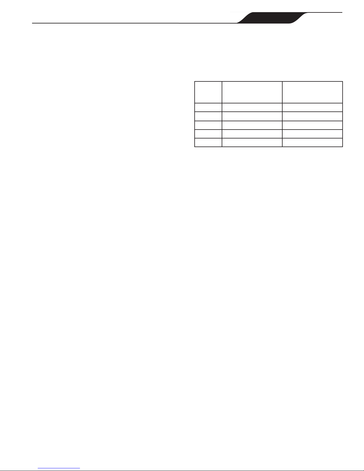
For installations of equipment up to 100 feet (30
m) from the water, refer to Table 1, the pipe sizing
chart. For installations of equipment more than
100 feet (30 m) from the water, the recommended
pipe size must be increased to the next size.
1½" 37GPM(140LPM) 50GPM(189LPM)
2" 62GPM(235LPM) 85GPM(322LPM)
2½" 88GPM(333LPM) 120GPM(454LPM)
3" 136GPM(515LPM) 184GPM(697LPM)
4" 234GPM(886LPM) 313GPM(1185LPM)
3. VS-FHP Pumps come equipped with unions on
both the suction and discharge ports. This feature
simplifies installation and service and eliminates
the possibility of leaks at threaded adapters.
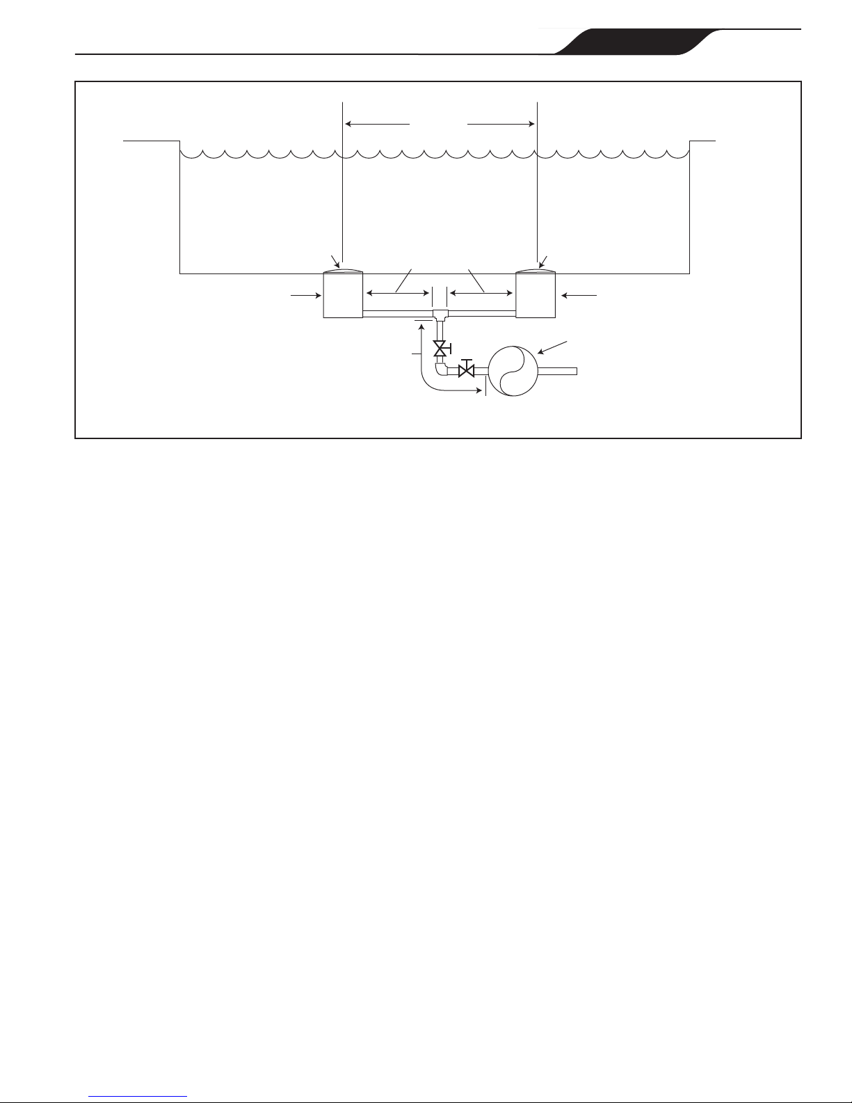
4. The VS-FHP Pump must be connected to at least
two (2) hydraulically-balanced main drains for
each pool pump suction line. Each drain must be
provided with covers that are listed or certified
to the latest published edition of ANSI/ASME
A112.19.8. The suction fittings of the main drains
must be at least three (3) feet (1 m) apart or at
different planes. The suction fittings can be a drain
and skimmer, two (2) drains, two (2) skimmers, or
a skimmer with an equalizer line installed. Check
the local codes for proper installation.
Toprevententrapment,thesystemmustbe
builtsoitcannotoperatewiththepumpdrawing
waterfromonlyone(1)maindrain.Atleasttwo
(2)maindrainsmustbeconnectedtothepump
whenitisinoperation.However,iftwo(2)main
drainsrunintoasinglesuctionline,thesingle
suctionlinemaybeequippedwithavalvethat
willshutoffbothmaindrainsfromthepump.
5. The piping must be well supported and not forced
together where it will experience constant stress.
6. Always use properly sized valves. Jandy Diverter
Valves and Jandy Ball Valves typically have the
best flow capabilities.
7. Use the fewest fittings possible. Each additional
fitting has the effect of moving the equipment
farther away from the water.
Ifmorethanten(10)suctionfittingsareneeded,
thepipesizemustbeincreased.
8. Every new installation must be pressure tested
according to local codes.
3. The pump and other circulation equipment must
be located more than five (5) feet from the water.
Choose a location that will minimize turns in the
piping.
InCanada,thepumpmustbelocateda
minimumofthree(3)meters(approximately10
feet)fromthewater(CSAC22.1).
4. The pump must be placed on a solid foundation
that will not vibrate. To further reduce the
possibility of vibration noise, bolt the pump to the
foundation, or place it on a rubber mat.
ZodiacPoolSystems,Inc.recommendsbolting
thepumpdirectlytothefoundation.
5. The pump foundation must have adequate drainage
to prevent the motor from getting wet. Protect the
pump from the rain and sun.
6. Proper ventilation is required for the pump to
operate normally. All motors generate heat that
must be removed by providing proper ventilation.
7. Provide access for future services by leaving a
clear area around the pump. Allow plenty of space
above the pump to remove the lid and basket for
cleaning.
8. If the equipment is in a potentially dark area,
provide adequate lighting.
When the pump is located up to 50 feet (15 m) from
the pool, the recommended minimum pipe size for the
suction side of the pump is two (2) inches (5 cm). For
suction lengths greater than 50 feet see Section 3.1.3.3
Step 2.
When the pump is located up to 50 feet (15 m) from
the pool, the recommended minimum pipe size for the
discharge side of the pump is two (2) inches (5 cm).
For discharge lengths greater than 50 feet (15 m) see
Section 3.1.3.3 Step 2.
1. If the pump is located below water level, isolation
valves must be installed on both sides of the pump
to prevent the back flow of pool water during any
routine or required servicing.
2. To help prevent difficulty in priming, install the
suction pipe without high points (above inlet of
pump - inverted “U”s, commonly referred to in
plumbing as an airlock) that can trap air.
Page 9
Jandy® FloPro™ Variable-Speed Pump Series VS-FHP | Installation and Operation Manual ENGLISH

Thepumpmustbepermanentlyconnectedtoa
dedicatedelectricalcircuit.Nootherequipment,
lights,appliances,oroutletsmaybeconnectedtothe
pumpcircuit,withtheexceptionofdevicesthatmay
berequiredtooperatesimultaneouslywiththepump,
suchasachlorinatingdeviceorheater.
1. The pump motor must be securely and adequately
grounded using the green screw provided. Ground
before attempting to connect to an electrical power
supply. Do not ground to a gas supply line.
2. Wire size must be adequate to minimize voltage
drop during the start-up and operation of the
pump. See Table 2 for suggested wire sizes.
3. Insulate all connections carefully to prevent
grounding or short-circuits. Sharp edges on
terminals require extra protection. For safety,
and to prevent entry of contaminants, reinstall all
conduit and terminal box covers. Do not force
connections into the conduit box.
4. Note the LED on the top of the electronics drive
enclosure. The LED is lit whenever power is
present at the motor, regardless of whether the
motor is running or not.
Sincethepumpisoperatedbyeitheravariable
speedcontroller(JEP-R),anAquaLink®RS
controller,oranAquaLinkPoolDigitalAssistant
(PDA),thepumpwillnotbeturnedonuntilitis
turnedonwithoneofthesecontrollers.
The correct voltage, as specified on the pump data
plate and the specification chart on page 25, is necessary
for proper performance and long motor life. Incorrect
voltage will decrease the pump’s ability to perform and
could cause overheating, reduce the motor life, and
result in higher electric bills.
It is the responsibility of the electrical installer to
provide data plate operating voltage to the pump by
ensuring proper circuit sizes and wire sizes for this
specific application.
The National Electrical Code (NEC, NFPA-70)
requires all pool pump circuits be protected with a
Ground Fault Interrupter (GFCI). Therefore, it is also
the responsibility of the electrical installer to ensure that
the pump circuit is in compliance with this and all other
applicable requirements of the National Electrical Code
(NEC) and any other applicable installation codes.
Failuretoprovidedataplatevoltage(within10%)
duringoperationwillcausethemotortooverheat
andvoidthewarranty.
1. The motor frame must be bonded to a reliable
grounding point using a solid copper conductor,
No. 8 AWG or larger. If the pump is installed
within five (5) feet (15 cm) of the inside walls
of the swimming pool, spa, or hot tub, the motor
frame must be bonded to all metal parts of the
swimming pool, spa, or hot tub structure and to
all electrical equipment, metal conduit, and metal
piping within five (5) feet (15 cm) of the inside
walls of the swimming pool, spa, or hot tub.
InCanada,thepumpmustbelocateda
minimumofthree(3)meters(approximately10
feet)fromthewater(CSAC22.1).
2. Bond the motor using the provided external lug.
See Figure 3.
Alwaysdisconnectthepowersourcebeforeworking
onamotororitsconnectedload.
Makesurethatthecontrolswitch,timeclock,or
controlsystemisinstalledinanaccessiblelocation,
sothatintheeventofanequipmentfailureora
looseplumbingfitting,theequipmentcanbeturned
off.Thislocationmustnotbeinthesameareaasthe
poolpump,filter,andotherequipment.
GROUND
NEUTRAL
BREAKER PANEL
CIRCUIT
BREAKER
Variable-Speed
Pump (230 VAC)
AC IN
AC IN
Bonding Lug
Terminal Block
Page 10 Jandy® FloPro™ Variable-Speed Pump Series VS-FHP | Installation and Operation Manual
ENGLISH

VS-FHP2.0 20A 12
*Assumesthree(3)copperconductorsinaburiedconduitand3%maximumvoltagelossinbranchcircuit.AllNationalElectricalCode
(NEC)ortheCanadianElectricalCode(CSA)andlocalcodesmustbefollowed.Tableshowsminimumwiresizeandbranchfuse
recommendationsfortypicalinstallation.
The VS-FHP pump can be operated by one (1)
of three (3) controllers: the variable-speed controller,
the AquaLink® RS controller (Rev O or later), or the
AquaLink PDA (Rev 4.0 or later). The FloPro variable-
speed pump communicates with the controllers via a
four-wire RS-485 interface.
The VS-FHP pump comes equipped with a factory
installed four-wire RS-485 cable. This RS-485 cable
comes with an additional shielded wire for grounding.
The shielded wire is to be grounded ONLY at
one end, at the VS-FHP pump. This is pre-installed at
the factory. At the other end, the shielded wire is pre-
trimmed at the factory.
If you need to cut the RS-485 cable to any custom
length, make sure to peel back and trim the ground
shielded wire.
To install the variable-speed controller:
TheinstallermustTURNONswitches1and2atthe
VS-FHPpumpwhenconnectedtothevariable-speed
controller.
Thevariable-speedcontrollerpartno.isJEP-R.
1. Remove power from the VS-FHP pump by
disconnecting the high voltage lines or by opening
any breaker to which the VS-FHP pump power is
connected.
Turnoffallswitchesandthemainbreakerinthe
VS-FHPpumpelectricalcircuitbeforestartingthe
procedure.Failuretocomplymaycauseashock
hazard,resultinginseverepersonalinjuryordeath.
2. Slide dip switches 1 and 2 up, so they are in the
ON position, and slide switches 3 and 4 down, so
they are in the OFF position. See Figure 4.
4-Position
DIP Switch
Variable-Speed
Pump
NOTE
Grounding Lug
RS485
Cable
BLACK
YELLOW
RED
GREEN
RS485 4321
RED
BLACK
YELLOW
GREEN
REMOTE CONTROL
54321
INPUT 2
INPUT 3
INPUT 4
COMMON
INPUT 1
Controller
(Rear View)
The VS-FHP pump comes with a
factory installed four-wire RS-485 cable.
3. Connect the other end of the cable to the
controller. Match the colors of the wires with the
appropriate connector positions as follows: 1- red,
2- black, 3- yellow, and 4- green.
4. Restore power to the VS-FHP pump and verify the
operation of the controller.
5. Refer to the Variable-Speed Controller Owner’s
Manual, H0311200, to operate the pump.
Page 11
Jandy® FloPro™ Variable-Speed Pump Series VS-FHP | Installation and Operation Manual ENGLISH

1. Make sure that the pump is turned off.
2. Make sure that the switch to the circuit breaker
that powers the pump motor is turned off.
Turnoffthepumpandthemainbreakerinthepump
electricalcircuitbeforestartingtheprocedure.Failure
tocomplymaycauseashockhazard,resultingin
severepersonalinjuryordeath.
Duetothepotentialriskoffire,electricshock,or
injuriestopersons,Zodiac®Pumpsmustbeinstalled
inaccordancewiththeNationalElectricalCode
(NEC),alllocalelectricalandsafetycodes,and
theoccupationalSafetyandHealthAct(OSHA).
CopiesoftheNECmaybeorderedfromtheNational
ProtectionAssociation,470AtlanticAve.,Boston,
MA02210,orfromyourlocalgovernmentinspection
agency.
InCanada,ZodiacPumpsmustbeinstalledin
accordancewiththeCanadianElectricalCode
(CEC).
To install an AquaLink® RS controller (Rev O or
later) or an AquaLink PDA (Rev 4.0 or later):
1. Remove power from the VS-FHP pump by
disconnecting the high voltage lines or by opening
any breaker to which the VS-FHP pump power is
connected.
Turnoffallswitchesandthemainbreakerinthe
VS-FHPpumpelectricalcircuitbeforestartingthe
procedure.Failuretocomplymaycauseashock
hazard,resultinginseverepersonalinjuryordeath.
2. Slide dip switches 1 and 2 down, so they are in the
OFF position. See Figure 5.
3. Select the desired address(es) for the VS-FHP
pump by setting dip switches 3 and/or 4, as shown
in Section 3.3, VS-FHP Pump Dip Switch Settings.
4. Connect the other end of the cable to an RS-485
connector on the AquaLink RS (or multiplexer
interface board), matching wire colors with
connector positions as follows: 1-red, 2-black,
3-yellow, and 4-green. See Figure 5.
5. Restore power to the VS-FHP pump and verify the
operation of the controller.
6. Refer to the appropriate manual to operate the
pump: AquaLink RS Owner’s Manual, 6593, or
AquaLink PDA Owner’s Manual, H0572300.
As shown in Figures 4 and 5, the 4-position dip
switch is located at the rear of the VS-FHP pump. This
dip switch serves two (2) functions: it selects the pump
address, and it determines what type of controller will
be used with the pump. The tables below show the dip
switch settings.
OFF OFF AquaLinkRSorAquaLinkPDA
ON OFF AquaLinkRSorAquaLinkPDA
OFF ON AquaLinkRSorAquaLinkPDA
ON ON VariableSpeedControllerJEP-R
OFF OFF PUMP1
ON OFF PUMP2
OFF ON PUMP3
ON ON PUMP4
Variable-Speed
Pump
4321
RED
BLACK
YELLOW
GREEN
RS485
Cable
BLACK
YELLOW
RED
GREEN
Connect to
AquaLink RS
RS-485 Connector
(or Multiplexer
Interface Board)
S1
S2
RESET
SERVICE
TIME OUT
FILTER PUMP
AUX 1
AUX 2
AUX 3
AUX 4
AUX 5
AUX 6
AUX 7
RS6 & RS8 ONLY
RS8 ONLY
HEATER SOLAR
POOL MODE
SPA MODE
SPA DRAIN
SPA FILL
AUTO
6 5 4 3 2 1
10987654321
4 3 2 1 4 3 2 1
AquaLink RS
RS-485 Connectors
4-Position
DIP Switch
Page 12 Jandy® FloPro™ Variable-Speed Pump Series VS-FHP | Installation and Operation Manual
ENGLISH

Lid with
Locking
Ring
and
Seal
Pump
Debris
Trap
Basket
(Inside
Pump)
Seal
Lid with
Locking
Ring
3. Make sure all necessary isolation valves are closed
to prevent pool water from reaching the pump.
4. Following the markings on the locking ring, turn
the ring counter-clockwise until the ‘START’
markings align with the ports. See Figures 6 and 7.
5. Carefully remove the lid with locking ring.
Whenpressuretestingasystemwithwater,air
isoftentrappedinthesystemduringthefilling
process.Thisairwillcompresswhenthesystem
ispressurized.Shouldthesystemfail,thistrapped
aircanpropeldebrisatahighspeedandcause
injury.Everyefforttoremovetrappedairmustbe
taken,includingopeningthebleedvalveonthe
filterandlooseningthepumpbasketlidwhilefilling
thepump.
Trappedairinthesystemcancausethefilter
lidtobeblownoff,whichcanresultindeath,
seriousinjury,orpropertydamage.Besureall
airisproperlypurgedoutofthesystembefore
operating.DONOTUSECOMPRESSEDAIRTO
PRESSURETESTORCHECKFORLEAKS.
Donotpressuretestabove35PSI.Pressure
testingmustbedonebyatrainedpool
professional.Circulationequipmentthatisnot
testedproperlymightfail,whichcouldresultin
severeinjuryorpropertydamage.
Whenpressuretestingthesystemwithwater,itis
veryimportanttomakesurethatthepumpbasket
lidiscompletelysecure.
1. Fill the system with water, using care to eliminate
trapped air.
2. Pressurize the system with water to no more than
35 PSI.
3. Close the valve to trap pressurized water in the
system.
4. Observe the system for leaks and/or pressure
decay.
5. If there are lid leaks, repeat this procedure. For
technical support, call 800.822.7933.
Page 13
Jandy® FloPro™ Variable-Speed Pump Series VS-FHP | Installation and Operation Manual ENGLISH

Neverrunthepumpwithoutwater.Runningthe
pump“dry”foranylengthoftimecancausesevere
damagetoboththepumpandmotorandwillvoid
thewarranty.
If this is a new pool installation, make sure all
piping is clear of construction debris and has been
properly pressure tested. The filter should be checked
for proper installation, verifying that all connections
and clamps are secure according to the manufacturer’s
recommendations.
Toavoidriskofpropertydamage,severepersonal
injuryordeath,verifythatallpoweristurnedoff
beforestartingthisprocedure.
1. Release all pressure from the system and open the
filter pressure release valve.
2. Depending on the location of the pump, do one of
the following:
- If the pump is located below the water level of
the pool, open the filter pressure release valve
to prime the pump with water.
- If the pump is located above the water level of
the pool, remove the lid and fill the basket with
water before starting the pump.
3. Prior to replacing the lid, check for debris around
the lid o-ring seat. Debris around the lid o-ring
seat will cause air to leak into the system and will
make it difficult to prime the pump.
4. Hand-tighten the lid to make an air tight seal. Do
not use any tools to tighten the lid: hand-tighten
only. Make sure all valves are open and the unions
are tight.
5. Restore power to the pump. Then turn on the pump
by following the instructions in the appropriate
manual: Variable-Speed Controller Owner’s
manual, H0311200, AquaLink® RS Owner’s
Manual, 6593, or AquaLink PDA Owner’s
Manual, H0572300.
6. Once all the air has left the filter, close the
pressure release valve.
7. The pump should prime. The time it takes to
prime will depend on the elevation and length of
pipe used on the suction supply pipe. See Section
3.1.3.3, Installation Recommendations, for proper
elevation and pipe size.
8. If the pump does not prime and all the instructions
to this point have been followed, check for a
suction leak. If there is no leak, repeat Steps 2
through 7.
9. For technical assistance, call Zodiac Technical
Support at 800.822.7933.
Inspect the pump debris tray basket for debris by
looking through the clear pump lid. Remove any debris,
because as debris accumulates, it will begin to block the
flow of water through the pump. Keep the basket clean
to improve the performance of the pump.
1. Turn off the power to the pump. If the pump is
located below the water level, close the isolation
valves on the suction and discharge sides of the
pump to prevent backflow of water.
2. Turn the lid's locking ring counter-clockwise until
'START' aligns with the ports. Carefully remove
the lid. (You may use a tool for leverage.)
Amisalignedbasketwillcausethelidtobe
improperlyseated,allowinganairleak,whichcould
resultinpumpdamage.
3. Lift the basket out of the pump.
4. Dispose of the debris and thoroughly clean the
basket, making sure all the holes are open. Using
a garden hose, spray the basket from the outside to
help clear the holes. Remove any remaining debris
by hand.
5. Replace the basket in the pump by aligning the
opening with the suction pipe. If aligned properly,
the basket will drop easily into place. Do not force
it into place.
6. Remove the lid seal and remove debris around the
lid seal seat, as this can allow air to leak into the
system. Clean the lid seal and place it on the lid.
7. Replace the lid with locking ring. Hand-tighten
the lid to make an air-tight seal. Do not use any
tools to tighten the lid: hand-tighten only.
Page 14 Jandy® FloPro™ Variable-Speed Pump Series VS-FHP | Installation and Operation Manual
ENGLISH

8. Verify that all valves have been returned to the
proper position for normal operation.
9. Open the pressure release valve on the filter, and
make sure it is clean and ready for operation.
10. Turn on the power to the pump. Once all the
air has been evacuated from the filter, close the
pressure release valve.
Thepumpmustbeprotectedwhenfreezing
temperaturesareexpected.Allowingthepump
tofreezewillcauseseveredamageandvoidthe
warranty.
Do not use antifreeze solutions in the pool,
spa, or hot tub systems! Antifreezeishighlytoxic
andmaydamagethecirculationsystem.Theonly
exceptiontothisisPropyleneGlycol.Formore
information,seeyourlocalpool/spasupplystoreor
contactaqualifiedswimmingpoolservicecompany.
1. Drain all water from the pump, system equipment,
and piping.
2. Remove the two (2) drain plugs. Store the drain
plugs in a safe location and reinstall them when
the cold weather season is over. Ensure drain plug
o-rings are not misplaced.
3. Keep the motor covered and dry. Do not cover
the pump with plastic, because this will create
condensation that will damage the pump.
ZodiacPoolSystems,Inc.recommendshaving
aqualifiedservicetechnicianorelectrician
properlydisconnecttheelectricalwiringat
theswitchorjunctionbox.Oncethepoweris
removed,loosenthetwo(2)unionsandstore
thepumpindoors.Forsafety,andtoprevent
entryofcontaminants,reinstallallconduitand
terminalboxcovers.
4. When the system is reopened for operation,
have a qualified technician or electrician make
sure all piping, valves, wiring and equipment
are in accordance with the manufacturer’s
recommendations. Pay close attention to the filter
and electrical connections.
5. The pump must be primed prior to starting. Refer
to Section 4.1, Start-up.
Page 15
Jandy® FloPro™ Variable-Speed Pump Series VS-FHP | Installation and Operation Manual ENGLISH

Zodiac strongly recommends that you call a qualified service technician to perform any repairs on the filter/pump
system. To locate a qualified technician, check your local yellow pages or visit www.zodiac.com and click on “Product
Support.”
Thecleaning/circulatingsystemis
notoperatingcorrectly.
Verifythatskimmerbaskets,pumpbasketandotherscreensareclean.Cleanas
necessary.
Checkfilterandcleanasnecessary.
Checkvalvepositions.Adjustasnecessary.
NOTEMultiplepiecesofequipmentoperatingatonetime(forexample,waterfalls,spa
jets,andsurfacereturns)willaffecttheproperoperationofthecleaningsystem.
Checkthecleaningsystemmanualtoensurethatthesystemisadjustedaccordingtothe
manufacturer'srecommendations.
Bubblesarepresentinthepump
basket.
Airisinthesystem.Checkthepoolorspawaterleveltoensurethatitisattheproperlevel
andairisnotbeingdrawnintothesuctionpiping.Ifthewaterisatthenormallevel,turnoff
thepump.Turnthelid'slockingringcounter-clockwiseuntil'START'alignswiththeports.
RemovethelidandcheckfordebrisaroundthelidsealseatORimproperinstallationof
thelidseal,aseitherconditionwillallowairtoleakintothesystem.Cleanthelidsealand
replaceitonthelid.Replacethelidonthepumphousing.Align'START'withtheportsand
turnthelockingringclockwiseuntil'LOCKED'alignswiththeports.Hand-tightenthelidto
makeanair-tightseal.Do not use any tools to tighten the lid. Turnthepumpbackon.
Airleaksarestillpresent. Checkthesuctionsidepipingunion.Whilethepumpisrunning,trytotightentheunion.If
thisdoesnotstoptheairleak,turnoffthepump.Loosenbothunionsandslidethepump
outoftheway.Remove,clean,andre-installbothuniono-rings.
Repositionthepumpnexttothepipingandsecuretheunionnutstothepump.Withclean
uniono-rings,hand-tighteningoftheunionsshouldcreateaseal.Iftheunionsstilldonot
seal,gentlytightenwithalargepairoftongue-and-groovepliers.
Do not over-tighten.
Thereisnoairinthesystem,but
thepressureisstilllow.
Itispossiblethatdebrisiscaughtinthepumpimpeller.Thepumpimpellermovesthe
water,andthevanesintheimpellercanbecomeblockedwithdebris.SeeSection
6.2, Service Technician Maintenance, 6.2.1, Blocked Impeller, inthismanualformore
information.
Thereisnodebrisblockingthe
impellerandthepressureisstill
low.
Thepumpimpelleranddiffuserareshowingsignsofnormalwear.Haveaqualifiedservice
technicianchecktheimpelleranddiffuserandreplaceasnecessary.
Ifthepumpispartofarelativelynewinstallation,itcouldbeanelectricalproblem.Contact
aqualifiedservicetechnician.Havethetechniciancheckforlooseelectricalconnections
andcheckthevoltageatthepumpmotorwhileitisinoperation.Thevoltagemustbewithin
10%ofthemotor'sdataplaterating.Ifthevoltageisnotwithin10%,contactaqualified
electricianand/orthelocalpowerserviceprovider.
Pumpsealisleakingair.Haveaqualifiedservicetechnicianreplacetheseal.
Thepumpisleakingwaterbetween
themotorandpumpbody.
Thisiscausedbyadamagedorfailedmechanicalseal.Replacetheseal.SeeSection 6.2,
Service Technician Maintenance, 6.2.3, Mechanical Seal Replacement,inthismanual.
Thepumpgetshotandshutsoff
periodically.
Makesurethatthereisadequateroomaroundthemotortocirculateairandkeepthe
motorcool.Haveaqualifiedelectriciancheckforlooseconnectionsandcheckthevoltage
atthepumpmotorwhileitisinoperation.Thevoltagemustbewithin10%ofthemotor's
dataplaterating.Ifthevoltageisnotwithin10%,contactaqualifiedelectricianand/orthe
localpowerserviceprovider.
Page 16 Jandy® FloPro™ Variable-Speed Pump Series VS-FHP | Installation and Operation Manual
ENGLISH

Pumpwillnotstart. Nopowertopump.
Makesurepumpisproperlyconnectedtohighvoltage.LEDontopofelectronicsenclosure
shouldbeilluminated.SeeSection 3.2, Electrical Installation,inthismanual.
Improperlow-voltagewiring.
Checklow-voltagewiringbetweenpumpandcontroller.Correctifnecessary.SeeSection
3.2, Electrical Installation,inthismanual.
Improperpumpaddresssetting.
Makesurethatpumpdipswitches3and4aresetproperlyfortheinstallation.Both
shouldbeOFFforusewithVariable-SpeedControllerorsettotheproperaddresswhen
connectedtoanAquaLink®RScontrolleroranAquaLinkPDA.SeeSection 3.3, VS-FHP
PumpDip Switch Settings, inthismanual.
Faultconditionexists.
Viewfaultmessageoncontrollerandcorrectfaultbeforeproceeding.Ifunsurehowto
correctfault,contacttechnicalsupportat800.822.7933.
Variable-SpeedControllerLCDis
notdisplayinginformation
pumpLEDsarenotilluminated.
Incorrectdipswitchsetting.
Makesurepumpdipswitches1and2arebothON.SeeSection 3.3, VS-FHP PumpDip
Switch Settings, inthismanual.
Improperlow-voltagewiring.
Checklow-voltagewiringbetweenpumpandcontroller.Correctifnecessary.SeeSection
3.2, Electrical Installation,inthismanual.
Controllerdisplays"Pumpnot
connected".
Improperlow-voltagewiring.
Checklow-voltagewiringbetweenpumpandcontroller.Correctifnecessary.SeeSection
3.2, Electrical Installation,inthismanual.
Improperpumpaddressset.
Ensurepumpdipswitches3and4aresetproperlyfortheinstallation.BothshouldbeOFF
forusewithVariable-SpeedControllerorsettotheproperaddresswhenconnectedtoan
AquaLinkRScontrolleroranAquaLinkPDA.SeeSection 3.3, VS-FHP PumpDip Switch
Settings, inthismanual.
Faultmessageappearson
controllerdisplay.
Faultconditionexists.
Viewfaultmessageoncontrollerandcorrectfaultbeforeproceeding.Ifunsurehowto
correctfault,contacttechnicalsupportat800.822.7933.
Page 17
Jandy® FloPro™ Variable-Speed Pump Series VS-FHP | Installation and Operation Manual ENGLISH

Thispumpmustbeservicedbyaprofessional
servicetechnicianqualifiedinpool/spainstallation.
Thefollowingproceduresmustbefollowedexactly.
Improperinstallationand/oroperationcancreate
dangerouselectricalhazards,whichcancause
highvoltagestorunthroughtheelectricalsystem.
Thiscancausepropertydamage,seriouspersonal
injury,and/ordeath.Improperinstallationand/or
operationwillvoidthewarranty.
Beforeservicingthepump,switchoffthecircuit
breakersatthepowersource.Severepersonal
injuryordeathmayoccurifthepumpstartswhile
yourhandisinsidethepump.
1. Turn off the pump. Switch off the circuit breaker
to the pump motor.
2. Remove the lid and basket.
3. Look inside the pump for debris. Remove any
debris found inside.
4. Replace the basket and lid.
5. Switch on the circuit breaker to the pump motor.
6. Turn on the pump, and see if the problem is
solved.
7. If the impeller is still blocked with debris and it
is not possible to remove the debris using Steps 2
through 4, the pump will need to be disassembled
in order to access the inlet and outlet of the
impeller.
Beforeservicingthepump,switchoffthecircuit
breakersatthepowersource.Severepersonal
injuryordeathmayoccurifthepumpstartswhile
yourhandisinsidethepump.
1. Turn off the pump. Switch off the circuit breaker
to the pump motor. If you are not replacing the
motor, do not disconnect the electrical wiring.
Ifyouarereplacingthemotor,ZodiacPool
Systems,Inc.stronglyrecommendsthata
qualifiedservicetechnicianorelectrician
properlydisconnecttheelectricalwiringatthe
pumpmotor.
Backplate
Diffuser
Screws (2)
O-ring
2. Turn off any valves to prevent pool water from
reaching the pump. Drain the water from the pump
by loosening the unions or removing the drain
plugs.
3. Using a 9/16" wrench, loosen the bolts connecting
the pump body to the motor backplate. See
Figure 8.
Pump Body
Motor Backplate
Bolts (6)
Fan Cover
4. Pull the motor and backplate out of the pump
body. Remove the pump body o-ring. The impeller
is connected to the motor shaft.
5. Using a No. 1 Phillips screwdriver, remove the
two (2) screws holding the diffuser. (The diffuser
is the cover over the impeller.) Then remove the
diffuser (See Figure 9).
6. Access the inlet and outlet of the impeller and
remove any debris.
Page 18 Jandy® FloPro™ Variable-Speed Pump Series VS-FHP | Installation and Operation Manual
ENGLISH

Mechanical Seal
Impeller
Backplate
Bolts (8)
Washers (8)
Backplate O-ring
Mechanical Seal
Impeller
Diffuser
Diffuser
Screws (2)
Diffuser
O-ring
1. Press the new carbon face seal half (see
Figure 12) on the motor shaft using a twisting
motion. Make sure the carbon surface is facing
toward the ceramic ring in the backplate.
7. Hold the motor shaft with a ¼" hex allen wrench
while unscrewing the impeller from the motor
shaft with your hand. Turn the impeller counter-
clockwise to unscrew it.
8. Inspect the impeller and diffuser for signs of
rubbing and/or damage.
Carbon Seal Surface
• Ceramic Face Seal
• Backplate Seal
• Carbon Face/ Spring
Side of Seal
• Impeller Side of
Mechanical Seal
2. While holding the motor shaft with a ¼" hex allen
wrench, thread the impeller onto the motor shaft.
Hand-tighten the impeller until it is secure. Do not
overtighten.
3. Replace the fan cover by replacing the screws.
4. Replace the diffuser over the impeller, using care
to insert alignment pins into the correct holes. The
molded-in arrow must point toward the handle of
the backplate.
5. Replace the two (2) small Phillips-head screws.
Tighten the screws to draw the diffuser against the
motor backplate.
6. To help prevent an airleak into the system, make
sure the diffuser o-ring, o-ring groove, and
o-ring seal area are clean and free of debris. If
you removed the diffuser o-ring, make sure you
install it into the groove you removed it from. (See
Figure 13.) If grease is used to retain the o-ring,
it must be silicone based. Do not use petroleum-
based grease. It will destroy the o-ring.
7. Slide the diffuser into the mating hole in the
pump body. While supporting the motor, start two
(2) screws on opposite sides. (This will hold the
motor in position while you start the other six (6)
screws.)
Topreventdamagetotheseal,
graspthelowerportionoftheseal(oppositethe
carbonface)wheninstallingit.
Toassistassembly,useonlywaterorsoapy
waterasalubricant.Anyotherlubricantwill
destroythesealafterashortperiodoftime.
Besuretokeepthesealandmatingparts
clean.
Page 19
Jandy® FloPro™ Variable-Speed Pump Series VS-FHP | Installation and Operation Manual ENGLISH

8. Tighten the screws lightly in a crossing “X”
pattern using a 9/16" wrench. Start with the inner
(middle) four (4), then the outer (top and bottom)
four (4) to draw the backplate to the body in an
even manner. Once all the screws are snug, torque
in the same order to 10 foot-pounds.
Diffuser O-ring
Screws (2)
Diffuser
Impeller
Mechanical Seal
Backplate O-ring
Backplate
Thisisatwo-partreplacementprocess.The
mechanical seal must be replaced as a set.
RefertoFigure14foranillustrationofthe
locationofthemechanicalsealandimpeller.
Donotdamagetheceramicorcarbonsurfacesofthe
seals.Ifthesurfacesaredamaged,leakswilloccur.
1. To access the mechanical seal, see Section 6.2.2,
Impeller Removal and Replacement.
2. Remove the carbon face seal half from the motor
shaft (See Figure 14). This is a spring-loaded seal.
Grasp the portion of the seal closest to the impeller
body and pull the seal off, using a twisting motion.
3. Remove the motor from the backplate, following
the steps in Section 6.2.4, Motor Replacement.
4. Place the backplate o-ring side down and force the
ceramic seal out using a screwdriver or drift.
5. Turn the backplate o-ring side up and insert the
new ceramic seal side into the backplate. Use
great care to press the seal in squarely with your
fingers. The ceramic is easily damaged and must
be pressed in using only your fingers or soft tools.
Do not use any lubricant other than water or soapy
water.
6. Install the backplate by following the relevant
steps in Section 6.2.2.1, Impeller Reassembly.
7. Install the motor by following the steps in
Section 6.2.4, Motor Replacement.
Diffuser
Diffuser O-ring
Pump Body
9. If the pump is located above the water level of the
pool, remove the lid and fill the basket with water
before starting the pump.
10. To help prevent an air leak into the system, remove
any debris around the lid seal seat.
11. Hand-tighten the lid to make an air tight seal.
Do not use any tools to tighten the lid.
12. Open the pressure release valve on the filter and
make sure it is clean and ready for operation.
13. Switch on the circuit breaker to the pump motor.
14. Turn on the pump and check the system for normal
operation.
15. Once all the air has left the filter, close the
pressure release valve.
Page 20 Jandy® FloPro™ Variable-Speed Pump Series VS-FHP | Installation and Operation Manual
ENGLISH
Other manuals for VS FloPro Series
1
Table of contents
Languages:
Other Jandy Swimming Pool Pump manuals
Popular Swimming Pool Pump manuals by other brands

Gullberg Jansson
Gullberg Jansson GJPACW1V-15 Installation and maintenance guide

atecpool
atecpool ATECF11 Installation Guide and User Manaul

SunSun
SunSun Wavemaker JVP-130 Operation manual

CARVIN
CARVIN SHARKJET 15SHJ-5-25-S1 owner's manual

Astral Pool
Astral Pool 1800 Series Installation and operating instructions

mundoclima
mundoclima MUPIR-H9 user manual