Jas JAS-HR800C User manual

HR800C Copyright
©
2005 JAS Teletech Co., Ltd. www.jasteletech.com
1
Home Repeater
User’s Guide
(Model#: JAS-HR800C)
JAS Teletech
504-29, JAS Bldg. Younnam-dong, Mapo-gu, Seoul, Korea
Tel: 82-2-330-5865 / Fax: 82-2-330-5879
www.jasteletech.com
The information provided by JAS Teletech Co., Ltd. is believed to be complete and accurate. However, no responsibility is
assumed by JAS Teletech Co., Ltd. for any business or personal losses arising from its use, or for any infringements of
patents or other rights of third parties that may result from its use

HR800C Copyright
©
2005 JAS Teletech Co., Ltd. www.jasteletech.com
2
Table of Contents
1. Security Precautions-----------------------------------3
2. Introduction
2.1 Overview------------------------------------------------3
2.2 Operational Concept-----------------------------------3
3. Installation
3.1 Contents & Feature------------------------------------4~5
3.2 Operating Displays and Connections---------------6~9
4. Appendix
4.1 Trouble Shooting--------------------------------------10
5. Specification---------------------------------------------11
6. Guidance forAntennas and Cable
6.1 Antenna-------------------------------------------------12~14
6.2 Cable-----------------------------------------------------14
7. Service-----------------------------------------------------15

HR800C Copyright
©
2005 JAS Teletech Co., Ltd. www.jasteletech.com
3
1. Security Precautions
Only use the power supply unit provided with the Home Repeater (DC 5 V / 1.2 A). Comply
with the connection values and ratings when connecting the device to the mains.
Protect the Home Repeater from dampness.
Never open the device. For electrical safety reasons it may only be opened by authorized
service technicians.
Dispose of the Home Repeater in environmentally safe manner.
Lightning protection is recommended for all installations
2. Introduction
2.1 Overview
Home Repeater is designed to improve wireless reception in poor indoor coverage areas.
Targeted as a cost effective solution for indoor coverage areas from 2,000-sq. ft. to 3,000-sq.
ft, JAS Home Repeater will allow users to operate handsets within a building or weak
coverage area while maintaining call clarity and quality.
2.2 Operational Concept
The Home Repeater takes the signal from a Pick-up antenna outside a building, amplifies it
and rebroadcasts it to the interior of the building with a Service antenna. The same process
occurs in the opposite direction taking the signal from the mobile phone and sending it
outside via the antenna and amplifier.
Pick-up
Antenna
RF Cable
(Base Transceiver Station)
Service Antenna

HR800C Copyright
©
2005 JAS Teletech Co., Ltd. www.jasteletech.com
4
3. Installation
3.1 Contents & Feature
3.1.1 Contents
The package contains the following items:
No. Contents Q’ty Remark
1
Home Repeater
1 unit Model #: HR800C
2
Adaptor
1 unit
Power Supply for Home Repeater
(110~220V/60Hz, +5V, 1.2A)
3
Bracket
1 unit
It can make easier to mount the
repeater on the wall
4
Screw
4 units
They are used to mount bracket
installation

HR800C Copyright
©
2005 JAS Teletech Co., Ltd. www.jasteletech.com
5
3.1.2 Features of Home Repeater
Front Panel Back Panel
Upper Panel Bottom Panel
Right Panel Left Panel

HR800C Copyright
©
2005 JAS Teletech Co., Ltd. www.jasteletech.com
6
3.2 Operating Displays and Connections
3.2.1 Operating Displays:
① To BTS : Port for receiving the signal from BTS, and a signal pick-up antenna should be
connected to the port.
② To Mobile: Port for emitting the amplified signal to mobiles, and service antenna such as
dipole, patch, omni antenna should connected to the port.
LED Displays
The front panel of the Home Repeater contains LED displays that show the operating state and
simplify installation and fault finding in the network.
LED State Status
On The Repeater has been switched on.
③Power Off The Repeater has been switched off.
Green The Repeater is working normally.
④Down Link Blinking The Repeater is shut down.
Green The Repeater is working normally.
⑤Up Link Blinking The Repeater is shut down.
①
③
④
⑤
②

HR800C Copyright
©
2005 JAS Teletech Co., Ltd. www.jasteletech.com
7
3.2.1 Set up the Home Repeater
To BTS To Mobile
RF Cable
AC 110/220
V
AC/DC Ada
p
to
r
Power Cable
Pick-up Antenna
Inside
Outside

HR800C Copyright
©
2005 JAS Teletech Co., Ltd. www.jasteletech.com
8
※Please read the following information before installing your Home Repeater.
Many mistakes can be avoided by considering over this information
3.2.1.1 Power Consumption
The power supply of the Home Repeater accepts 110~220V, +5V, and 1.2A.
3.2.1.2 Operating Environment
Temperature range: 0℃~+50℃
Maximum Humidity: 95%
3.2.1.3 You need to determine the following things for the Home Repeater installation:
A position where the pick-up antenna is to be installed:
a. The pick-up antenna should be located in a position with at least a
3’radius clear of obstructions and other radiating elements.
b. You may decide the position with checking out with the antenna level
bars of your mobile phone. If the number of antenna level bars of
your mobile phone is one or two when you check on the position of
patch antenna, it would be OK.
However, if there is no antenna level bars on your mobile phone, you had
better change the position of patch antenna.
You should decide the position where the Home Repeater should be installed.
a. You may install the Home Repeater on the wall or using wall mount
bracket that are provided with Home Repeater.
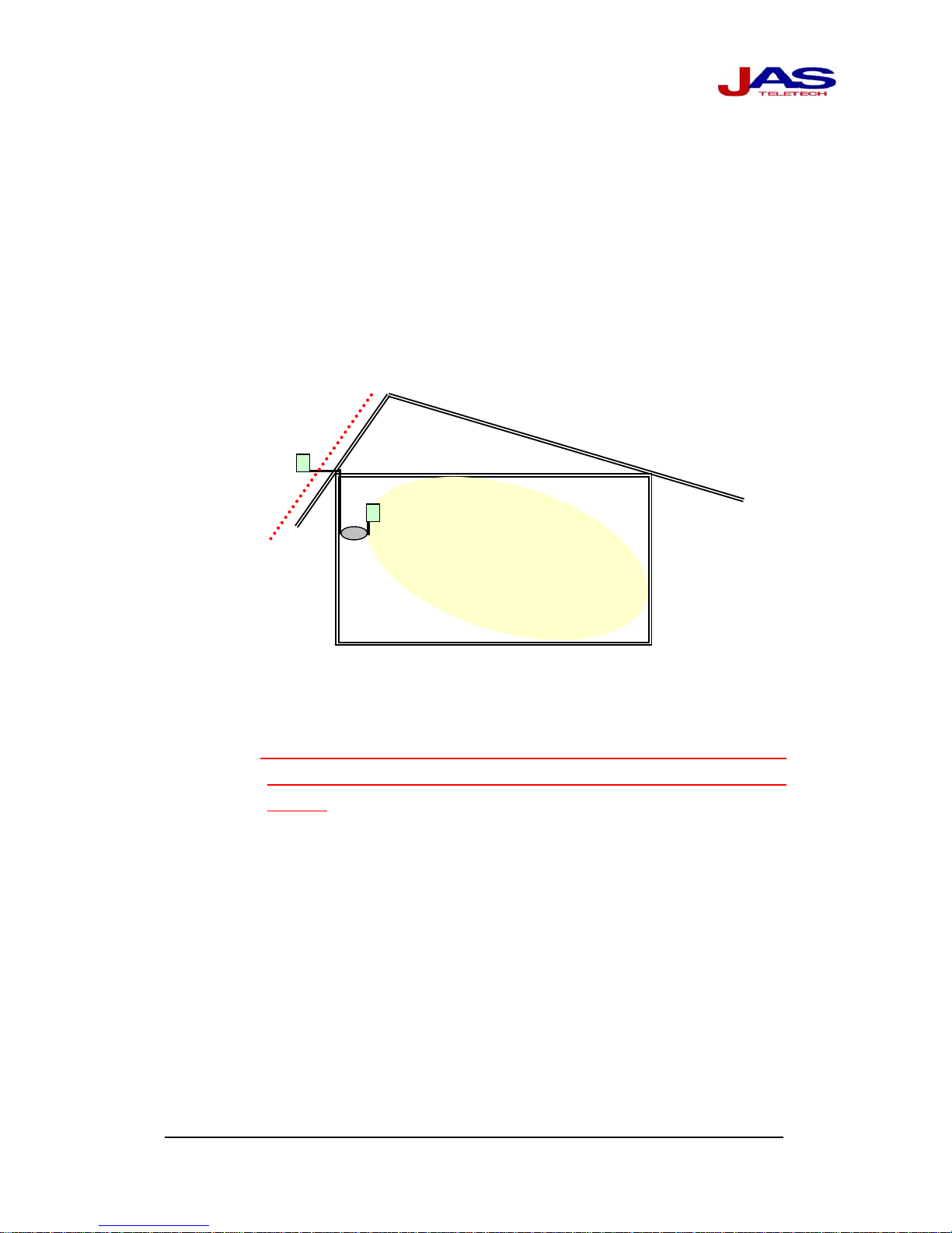
※When you install Home Repeater, you must consider minimum isolation
between pick-up antenna and Home Repeater.
; If there is not enough isolation insurance, the Home Repeater will be defective.
As you can see the following illustration, the Home Repeater and pick-up
antenna must be isolated from each other. If the building is made of concrete
or other signal blocking material, the isolation is sufficient.
After you confirm the length of cable needed to connect from the pick-up
antenna to the Home Repeater, you may connect the Home Repeater and
pick-up antenna. The cable should be tied up on the wall or ceiling between
pick-up antenna and Home Repeater.

HR800C Copyright
©
2005 JAS Teletech Co., Ltd. www.jasteletech.com
9
※IMPORTANT!
1. The Home Repeater is designed to be used to cover only inside of buildings. It is NOT designed
to be used to cover outside of building such as playground, open area parking lots, farmland,
and etc.
2. The Home Repeater may penetrate down to the lower floor depending on the amount of mass or
materials contained within the floor. There is no way to know whether the signal can penetrate
to the lower floor without installing another Home Repeater or additional service antenna.
3.2.2Connection
It is very important to connect The Home Repeater with antennas and cables. For
selection of antennas and cable, you may read section 6 for guidance of antennas
and cable
Pick-up Antenna
Isolation
Home Repeater
Service Antenna
Roof

HR800C Copyright
©
2005 JAS Teletech Co., Ltd. www.jasteletech.com
10
4 Appendix
4.1 Trouble Shooting
If Home Repeater does not operate properly after installation and the signal level of your
mobile is same as before, make sure that the installation procedures as described in this manual
were followed correctly. You may check out the following step for the inspection
4.1.1 Inspection Procedure
No. Inspection Step Remark
1 Power LED The green light should be on if the power is on.
2 Down link LED
The green light should be on, if it is normal. If
green and red light is blinked, please check next
step.
3 Up link LED
The green light should be on, if it is normal. If
green and red light is blinked, please check next
step.
4 Connection of the port
(To mobile & To BTS)
To Mobile: The dipole antenna (Service
antenna) should be connected
tightly.
To BTS: The donor antenna (Patch antenna)
should be connected tightly.
5 Cable connection to donor
antenna
The cable should not be broken or any other
damaged.
♦If the signal level of your mobile is still same as before, you might change the donor
antenna location to get better signal from base station.
♦If there is any obstacle between Home Repeater and mobile, the signal of your mobile
would be fluctuated. You may check the location of Home Repeater and re-install it.
♦If the red light in LEDs of Home Repeater is still blinked and the signal level of mobile
is same as before although you inspect them through the above procedure, you may
contact sales agent or manufacturer.

HR800C Copyright
©
2005 JAS Teletech Co., Ltd. www.jasteletech.com
11
5 Specification
◎ Model Name : HR800C
Specifications
No. Parameters
Downlink Uplink
Remarks
1 Frequency Range 869 ~ 894 MHz 824 ~ 849 MHz
2 Output Power +7dBm [Max.]
3 Gain 50dB ±2dB/Fc
4 Gain Flatness ≤7dB
5 P1dB ≥+14dBm
6 Output IP3 ≥+24dBm
7 Down/Up Link
shutdown Function ≥+9dBm
8 Noise Figure ≤7dB @ Full Band
9 V.S.W.R ≤1 : 2.0 Up/Down Link Port
10 Impedance 50Ω
11 Operating Temperature 0°C~ +50°C
12 Dimension (W x H x D) 120mm x 97mm x 43mm [Max.] Without Connector
13 Weight ≤600 g
14 RF Connector SMA-Type (Female) Up/Down Link Port

HR800C Copyright
©
2005 JAS Teletech Co., Ltd. www.jasteletech.com
12
6. Guidance for Antennas and Cable
This is a guidance for customers’ selection of antennas and cables. You may read carefully and try to find
out the best type of each antennas and cables.
6.1 Antenna
When you receive the Home Repeater, you need two antennas and some length of cable. One of
the antennas is pick up antenna that is for receiving signal from outside of the building. The
other antenna is service antenna that is for transmitting signal to inside of the building.
6.1.2 Pick-upAntenna
Normally, patch or yagi antenna is used for pick up antenna that is installed outside of
building that has 7 ~ 12dBi gain. This antenna should be installed after confirmation
of line of sight. Line of sight means that the antenna should be able to see the base
station and to be located on the direction to the base station. If not, the signal is not
enough for the Home Repeater to emit to the mobile.
If you can not find a location or direction of base station, you may use your mobile
phone to confirm the position of pick-up antenna. When you see the level of antenna
level on your mobile phone, it should be at least 2 or 3 bars for the position of pick-up
antenna.
If you want to get stronger signal from base station, you may use another antenna that
has more gain such as 10dBi or 12dBi. <Figure 3> shows different types of pick-up
antennas
6.1.3 Service Antenna
Normally, patch or dipole antenna is used for the service antenna. Dipole antenna has
0dBi gain. If you would like to use patch antenna for service antenna, you might need
to use cable that you also consider the cable loss.

HR800C Copyright
©
2005 JAS Teletech Co., Ltd. www.jasteletech.com
13
Pick-Up & Service Antennas Specification
- Frequency Range: CDMA
- Gain; 12dBi
- Polarization: Vertical
- Horizontal Beam Width: 42°
- Vertical Beam Width: 38°
Yagi
Antenna
- Frequency Range: PCS or GSM1800
- Gain: 10dBi/12dBi
- Horizontal Beam Width: 43°
- Vertical Beam Width: 40°
- Frequency Range: PCS or GSM1800
- Gain: 8dBi
- Polarization: Vertical
- Horizontal & Vertical Beam Width:
70°
Patch
Antenna
- Frequency Range: CDMA Band
- Gain: 7dBi
- Polarization: Vertical
- Horizontal & Vertical Beam Width:
70°
Dipole
Antenna
- Frequency Range: CDMA, PCS, or
GSM 1800
- Gain: 0dBi
- Polarization: Vertical
<Figure 3 Different types of antennas>

HR800C Copyright
©
2005 JAS Teletech Co., Ltd. www.jasteletech.com
14
6.1.4 Example of using antenna
Patch to Dipole
This is a general case of using antennas. You may use patch antenna for pick-up antenna
and dipole antenna for service antenna. You can use this antenna for small office and
home which has dimension up to (32ft x 32ft).
Patch to Patch
You may use patch antenna for both pick-up and service antenna. You can use this antenna
for dimension up to (42ft x 42ft).
Yagi to Patch (Dipole)
If it is not easy to install Patch antenna for donor, for instance, basement, you may use yagi
antenna for pick-up antenna.
6. 2 Cable
The RF cable is for connection between the Home Repeater and patch antenna (Pick-up
antenna). The following information is the specification of the RF cable.
Specification Remark
Model RG 58
Cable Loss 0.7dB/3.28ft
Connector type SMA type
※As much as you use the cable, there would be more loss on the cable. Therefore, you
should calculate the maximum cable length regarding antenna usage. Because the
Home Repeater has 50dB gain which is fixed.

HR800C Copyright
©
2005 JAS Teletech Co., Ltd. www.jasteletech.com
15
7. Service (Customer Care)
If you need further assistance with your installation or any problem with Home Repeater, please call
representative.
* Warning
This device shall only be installed and operated by the FCC licensee for the cellular telephone service, in
accordance with the Booster Rules contained in Rule Parts 90.219 and 22.383.
Table of contents
Popular Repeater manuals by other brands

Elko
Elko RFRP-20 quick start guide

NHRC
NHRC NHRC-4/M2 Installation and setup guide

B+B SmartWorx
B+B SmartWorx 232OPDRI quick start guide

Maxon
Maxon TDR Series user manual

Helmholz
Helmholz PROFIBUS Compact Repeater instruction manual

Rose electronics
Rose electronics Orion XT OX2-CNV-01CC Installation and operation manual