DEVI DEVIlink RU User manual
Installation Guide
DEVIlink™ RU
Electronic Repeater Unit
www.devi.com

DEVIlink™ RU
Installation Guide2
1 Introduction
The DEVIlink™ RU Repeater Unit is used for extending the
wireless transmission range between DEVIlink™ CC Control-
ler, DEVIlink™ RS Room thermostats and other connected
components in DEVIlink™ system.
This is particularly useful in larger installations where physi-
cal distance between components may prevent proper
wireless connection e.g. where radio transmission barriers
occur, i.e. where radio signals may be obstructed by heavy
walls, metal objects, etc.
Table of Contents
1 Introduction � � � � � � � � � � � � � � � � � � � � � � � � � � � � � � 2
1.1 Technical Specifications . . . . . . . . . . . . . . . . .3
1.2 Safety Instructions . . . . . . . . . . . . . . . . . . . . . .5
2 Mounting Instructions� � � � � � � � � � � � � � � � � � � � � 5
3 Settings� � � � � � � � � � � � � � � � � � � � � � � � � � � � � � � � � � � 6
3.1 Initiate transmission test
on the Repeater Unit . . . . . . . . . . . . . . . . . . . .6
3�2 Factory reset � � � � � � � � � � � � � � � � � � � � � � � 7
4 Symbols � � � � � � � � � � � � � � � � � � � � � � � � � � � � � � � � � � 7
5 Radio Equipment Directive � � � � � � � � � � � � � � � � 8
6 Warranty� � � � � � � � � � � � � � � � � � � � � � � � � � � � � � � � � � 8
7 Disposal instructions � � � � � � � � � � � � � � � � � � � � � � 8
DEVIlink™ RU
3Installation Guide
The system supports up to three Repeater Units installed in
a chain between the relevant DEVIlink™ Room thermostat
and the DEVIlink™ CC Controller.
More parallel chains of Repeater Units from a Controller are
possible.
1�1 Technical Specifications
Operation voltage 230 VAC/15 V DC ±10%
Ambient temperature -10 to +40 °C
Storage temperature -20 to +65 °C
Ball pressure test tempera-
ture
75 °C
Pollution degree 2 (domestic use)
Transmission frequency 868.42 MHz
Transmission range up to 30 m in normal
buildings
Max. repeaters in a chain 3
Transmission power Max. 1 mW
Software class A
IP class 21
Length of mains cable 3.0 m

DEVIlink™ RU
Installation Guide4
Dimensions Dimensions 125 x 107 x
25 mm
Weight 100 g
Electrical safety and Electro-Magnetic Compatibility for
this product is covered by the compliance with the EN/IEC
Standard “Automatic electrical controls for household and
similar use”:
▪EN/IEC 60730-1 (general)
▪EN/IEC 60730-2-9 (thermostat)
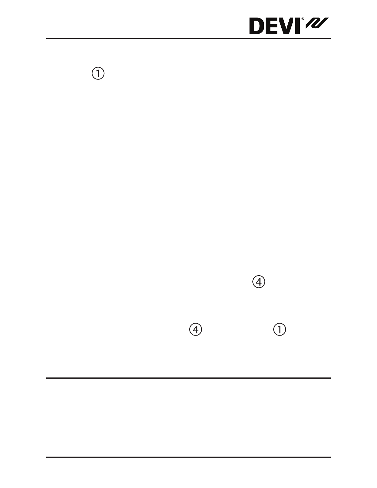
LED Indicator (red)
Round front Cover hidding push button
Transformer/power supply plug
DEVIlink™ RU
5Installation Guide
1�2 Safety Instructions
Make sure the power supply to the thermostat is turned off
before installation.
Please also note the following:
▪The installation of the thermostat must be done by an
authorized and qualified installer according to local
regulations.
▪The thermostat must be connected to a power supply
via an all-pole disconnection switch.
▪Always connect the thermostat to continuous power
supply.
▪Do not expose the thermostat to moisture, water,
dust, and excessive heat.
2 Mounting Instructions
After the Repeater Unit has been assigned to the Controller,
disconnect the temporary 230 V power supply and mount
the Repeater Unit on the right location.
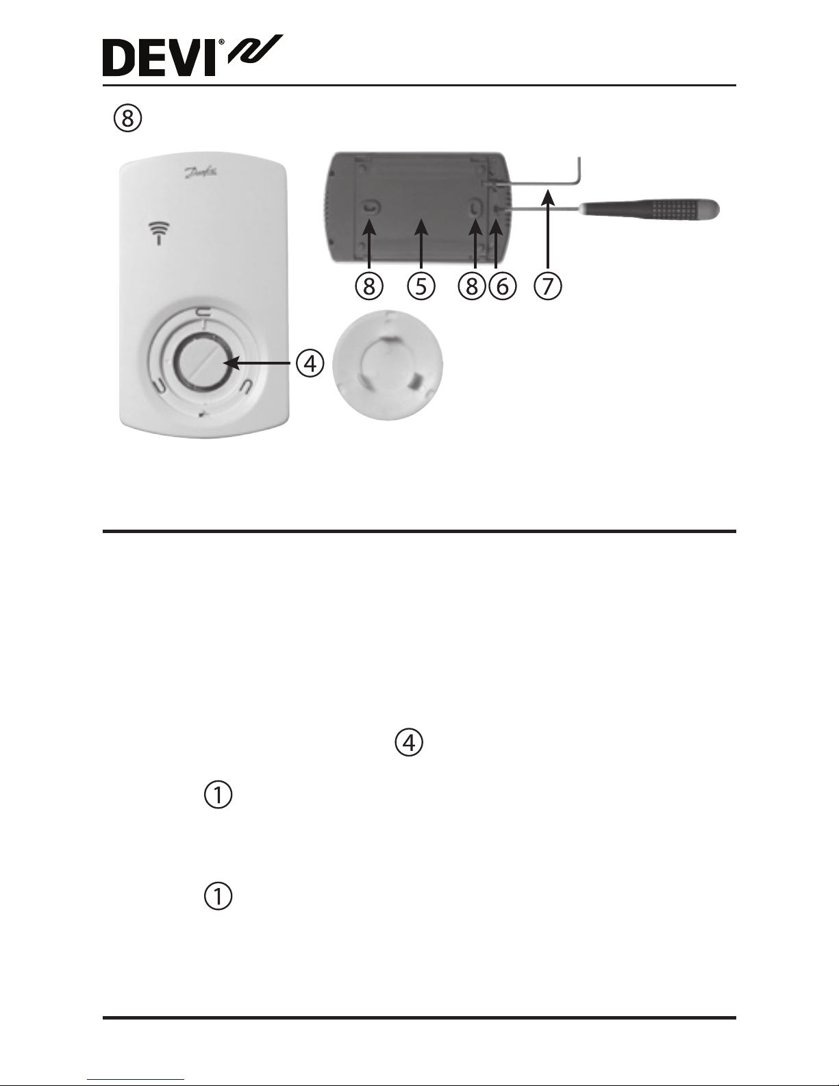
Push button
Back plate
Hole for releasing front cover
Back plate lock/unlock (Unbrako)
DEVIlink™ RU
Installation Guide6
Screw hole for wall mounting
3 Settings
Configuring of the DEVIlink™ RU Repeater Unit to the
DEVIlink™ CC by adding to it as a service device. See the
DEVIlink™ CC manual for further information.
3�1 Initiate transmission test on the Repeater Unit
▪Press the push button .
▪LED goes ON.
If Link test is satisfactory
▪LED goes OFF.
▪Mount the front cover again.
DEVIlink™ RU
7Installation Guide
If Link test is unsatisfactory
▪LED flashes 5 times.
If the transmission between DEVIlink™ RU Repeater Unit
and DEVIlink CC is not successful
1. Try to relocate the DEVIlink™ RU Repeater Unit.
2. Or install additional DEVIlink™ RU Repeater Units (up
to three)
3�2 Factory reset
▪Disconnect the DEVIlink™ RU Repeater Unit from the
power supply.
▪Release the round front cover hiding push button
▪Press and hold down the push button .
▪Meanwhile plug in the power supply again.
▪Release the push button when the LED goes ON
and OFF.
4 Symbols
LED modes:
▪LED permanent lighting – ON
▪No LED light – OFF
DEVIlink™ RU
Installation Guide8
5 Radio Equipment Directive
SIMPLIFIED EU DECLARATION OF CONFORMITY
Hereby, Danfoss A/S declares that the radio equipment type
DEVIlink™ RU is in compliance with Directive 2014/53/EU
The full text of the EU declaration of conformity is available
at the following internet address: devi�danfoss�com
6 Warranty
YEAR
WARRANTY
7 Disposal instructions

DEVIlink™ RU
9Installation Guide

DEVIlink™ RU
Installation Guide10

DEVIlink™ RU
11Installation Guide Produced by Danfoss © 06/201708096204 & VIJWB202
Danfoss A/S
Electric Heating Systems
Ulvehavevej 61
7100 Vejle
Denmark
Phone: +45 7488 8500
Fax: +45 7488 8501
E-mail: [email protected]
Web: www.DEVI.com
Danfoss can accept no responsibility for possible errors in catalogues, brochures and other printed material. Danfoss reserves the right to alter its products
without notice. This also applies to products already on order provided that such alterations can be made without subsequential changes being necessary
in specifications already agreed. All trademarks in this material are property of the respective companies. DEVI and the DEVI logo-type are trademarks of
Danfoss A/S. All rights reserved

Table of contents


