I NoUSERsEm
REFERSERVKZLNOTOCWlJflED SERVKX PERSONNEL
ThelightningIlashwitharrowheadsymbol,withinanequilateraltriangle,is
A intendedtoalerttheusertothepresenceofuninsulated
‘dangerousvoltage’
withintheproduct’senclosure,that maybeofsufficientmagnitudetoconstitutea
riskofelectricshocktopeople.
n
Theexclamationpointwithinanequilateraltriangleisintendedtoalerttheuserto
1 thepresenceofimportantoperatingandmaintenance(servicing)
. instructionsintheliteratureaccompanyingtheunit.
WARNING
: TO PREVENT FIRE OR SHOCK HAZARD, DO NOT
EXPOSE THIS UNIT TO RAIN OR MOISTURE.
Connect the power cable to the 24VAC power terminal block.
(Use only isolating transformer)
Thank you for purchasingthis colorvideocamera.To obtainthe bestresultafrom
your new camera,read this instruction manual carefully before’use : retain the
manualforfuturereference.
CONTENTS
PRECAUTIONS .................................... ........................................................................................................... 3
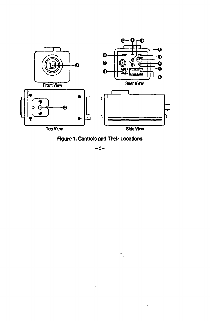
CONTROLS AND THEIR LmATI&S ...........................................................................................
5
CONNECTION .................................................................................................................................................. 9
MOUNTING THE LENS ............................................................................................................................ 9
INSTALLATION ........................................................................................................................................... 10
ADJUSTING THE WHITE BALANCE ........................................................................................... 11
PREVENTING SMEAR AND BLO(,MING ................................................................................... 12
MECHANICAL FOCUS (BACK FO(-US) ADJUSTMENT ................................................... 12
CONNECTIONS -&,R LINE L0f-K OPERATION ...................................................................... 15
SPECIFICATIONS ........................................................................................................................................ 16