To prevent fire or shock hazard. do not
expose the unit to rain or moisture. *
n 1 This symbol is intendedto alert the user to the presence
of important operating and maintenance (servicing)
.
SAlnm instructionsin the literatureaccompanyingthe appliance.
A
This symbol is intendedto alert the user to the presence
of uninsulated*dangerousvoltage’ within the product’s
enclosure, that may be of sufficient magnitude to
s*WE.5 constitute a risk of electric shockto people.
I ICAUTION:
Warning This equipmenthasbeentestedand found to comply with
the limits for a ClassA di ital device, pursuant to part
15 of the FCC Rules. T ese limits are designed to
R
provide reasonable protection against harmful
interference when the equipment is operated in a
commercial environment. This equipment generates,
uses. and can radiateradio frequency energy and. if not
installed and used in accordance with the instruction
manual. may cause harmful interference to radio
communications. Operation of this equipment in a
residential area is likely to cause harmful interference,
in which case the user will be required to correct the
interferenceat hisown expense.
Caution Any changes or modifications in construction of this
device, which are not expressly approved by the
party responsible for compliance, could void the
user’s authority to operate the equipment.
-l-
[PRECAUTIONS I
1. Do not attempt to disassemble the camera.
In order to prevent electric shock, do not remove screws or
cover. There are no user serviceable parts inside.
Refer all servicing to qualified service personnel.
2. Handle the camera with care.
Thecameracould be damagedby improper handlingor storage.
3. Do not expose the camera to rein or moisture. or try
to operate it in wet areas.
Take immediate action if the camera becomes wet. Turn the
power off and refer servicing to qualified service personnel.
Moisture can damage the camera and also create a danger of
electric shock.
4. Do not use stron
cleaning the camera 8, or abrasive detergents when
ody.
Use a dry cloth to clean the camera when dirty. In case the
dirt is hard to remove, use a mild detergent and wipe gently.
5. Never point the camera toward the sun.
Whether the camera is used outdoors or not, never point it
toward the sun. Use caution when operating the camera in the
vicinity of spotlights or other bright lights, and light
reflecting objects.
6. Do not operate the camera beyond its temperature.
humidity or power source ratings.
Do not use the camera in an extreme environment where high
temperature or high humidity exists. Use the camera under
conditions where temperatures are between 14’F-122°F f-1OC
- +5Oc:). and humidity is below 65%. For the correct power
supply. refer to the specification sheet,
Caution:
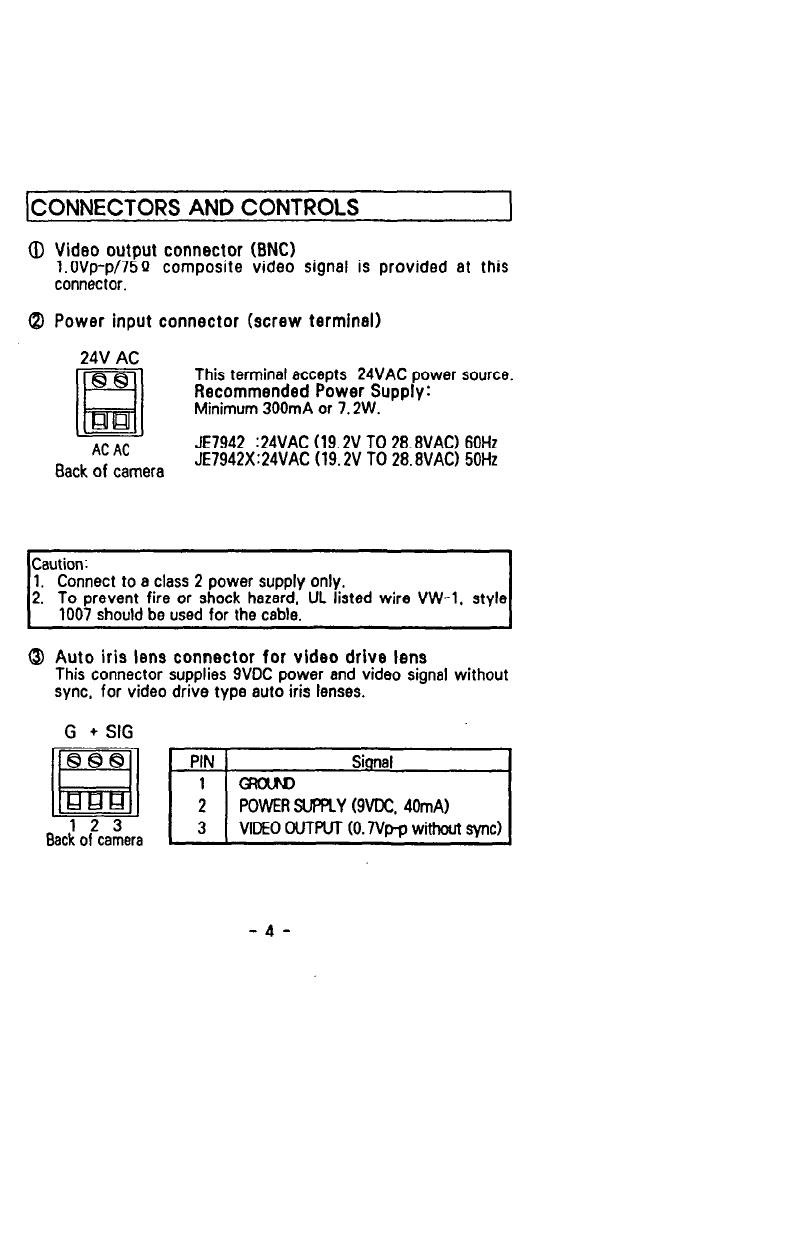
To prevent fire or shock hazard, the UL listed wire VW-I. style
1007should be used for the cable.
-2-