SCS135
3
Specifications
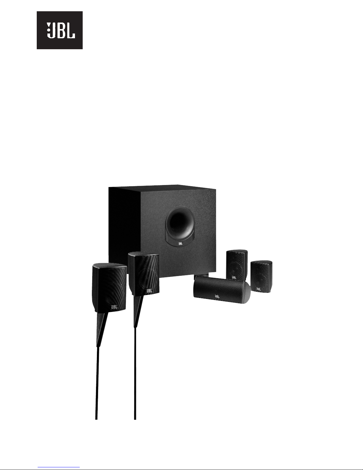
SCS135 SYSTEM
Frequency Response 35Hz - 20kHz (-6dB)
Satellites
Recommended Power 10 - 100 watts
Impedance 8 ohms nominal
Sensitivity 86dB @ 1 watt/1 meter
Tweeter One 1/2" titanium-laminate dome, video-shielded
Midrange One 3" driver, video-shielded
Dimensions (H x W x D) 4-3/8" x 3-3/16" x 3-3/4"
111mm x 81mm x 95mm
Weight 1.1lb/0.5kg
Center Channel
Recommended Power 10 - 50 watts
Impedance 8 ohms nominal
Sensitivity 86dB @ 1 watt/1 meter
Tweeter One 1/2" titanium-laminate dome, video-shielded
Midrange Dual 3" drivers, video-shielded
Dimensions (H x W x D) 3-1/4" x 7-5/8" x 3-3/4"
83mm x 194mm x 95mm
Weight 1.89 lb/0.86kg
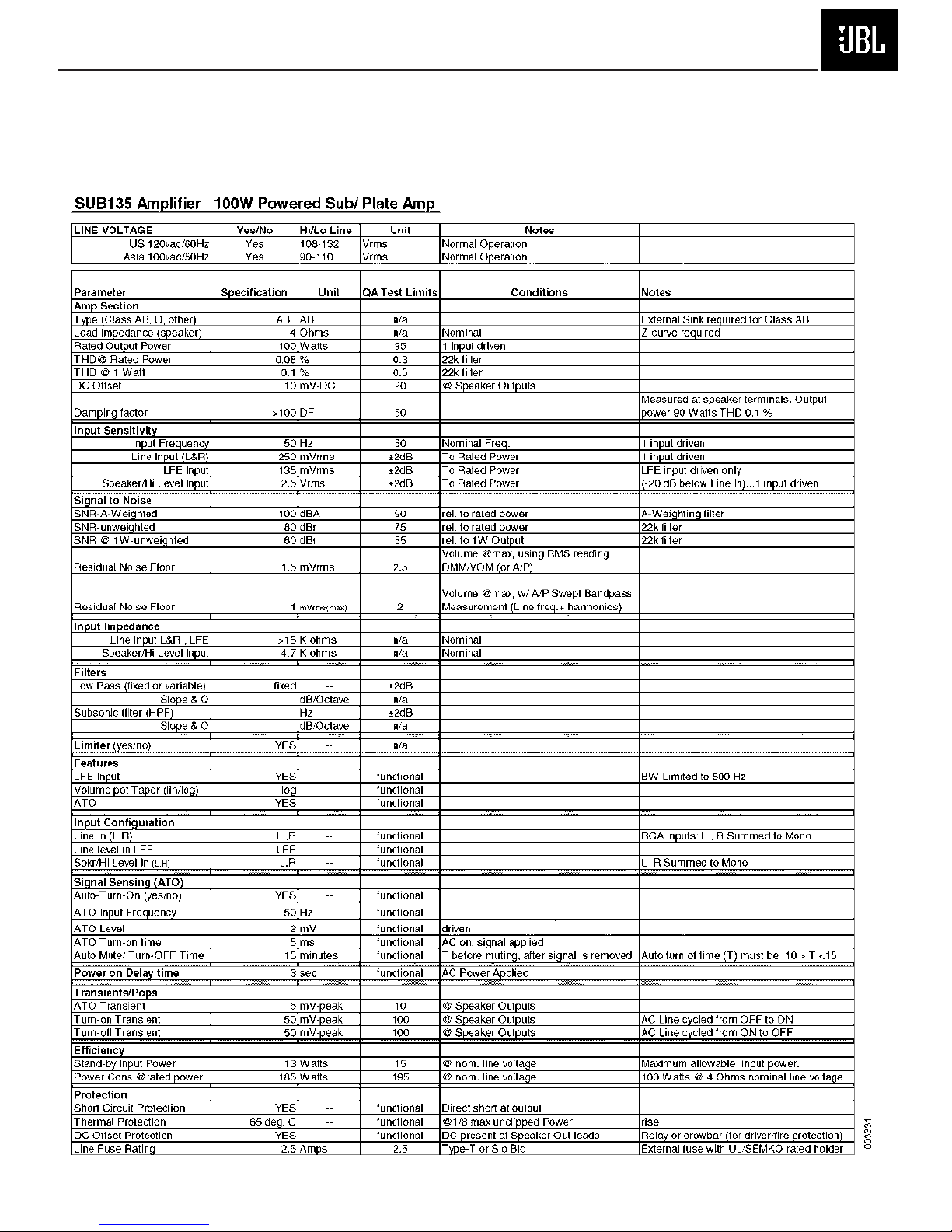
SUB135 Subwoofer 100 watts RMS
8" woofer, bass-reflex enclosure
Dimensions (H x W x D) 15" x 13" x 14"
381mm x 330mm x 356mm
Weight 30 lb/13.6kg
Refinements may be made on occasion to existing products without notice, but will always meet or
exceed original specifications unless otherwise stated.
Simply Cinema is a registered trademark of JBL, Incorporated.