Jefferson JEFC050V10B-230 User manual

User Manual
v.1.1
JEFC050V10B-230
V-PUMP •DIRECT DRIVE

USER MANUAL
JEFC050V10B-230
50L V-PUMP AIR COMPRESSOR •3HP •10Bar •Direct Drive
www.jeffersontools.com
2

USER MANUAL
JEFC050V10B-230
50L V-PUMP AIR COMPRESSOR •3HP •10Bar •Direct Drive
www.jeffersontools.com 3
Introduction 4
Specications 4
Unpacking & Assembly 5
Equipment Identication 6
Before First Use 7
Safety Guidelines 8
Warning Labels 10
Operation Guide 11
Troubleshooting 12
Maintenance 13
Environmental Protection 14
WEEE Waste Electrical and Electronic Equipment Statement 14
RoHS Directive 2011/65/EU - Compliancy 14
Parts List & Diagram - Main Assembly 15
Parts List & Diagram - Pump Assembly 16
EC Declaration of Conformity 17
Limited Warranty Statement 18
Important: This manual has been compiled by Jefferson Tools and is an integrated part of the product with which it's enclosed and should be
kept with it for the future reference.
This manual describes the purpose for which the product has been designed and contains all the necessary information to ensure its correct and
safe use. We recommend that this manual is read before any operation or, before performing any kind of adjustment to the product and prior to
any maintenance tasks. By following all the general safety instructions contained in this manual you will help to ensure operator safety and extend
the potential lifespan of the equipment.
All photographs and drawings in this manual are supplied by Jefferson Tools to help illustrate the operation of the product. Whilst every effort
has been made to ensure accuracy of information contained in this manual, our policy of continuous improvement determines the right to make
modifications without prior warning.
Note: The information contained in this Instruction Manual is designed to assist you in the safe operation and maintenance of the compressor.
Some illustrations in this Instruction Manual may show details or attachments that differ from those on your own compressor. Contact your
nearest Jefferson Dealer if you are unsure about any information included in this manual or require any additional information about the safe use,
operation maintenance, or repair of this equipment.
CONTENTS
USER MANUAL
JEFC050V10B-230
50L V-PUMP AIR COMPRESSOR •3HP •10Bar •Direct Drive
www.jeffersontools.com
4
• Aluminium head with cast-iron cylinders ensures durability & long-running operation
• Direct-drive assembly with pump head connected to heavy-duty induction motor for reliable and quiet operation
• Suitable for general-purpose workshop applications
• Welded tank fully-compliant with the latest European manufacturing & safety standards
• Fitted with an automatic pressure cut-out switch with twin gauges displaying tank and working pressures
• Equipped with transportation handle, front rubber mounted feet and rear wheels to assist manoeuvrability
• Powder-coated nish on the tank provides protection against corrosion
SPECIFICATIONS
JEFC050V10B-230
Tank Capacity: 50L
Input Voltage ~ Frequency: 230V ~ 50Hz
Motor Output: 3HP / 2.2kW
Plug Type / Rated Supply: UK 3-Pin / 13A
Cylinders: 2
Pump Speed: 2850rpm
Air Displacement: 14.6cfm (412 L/min)
Free Air Delivery: 8.7cfm (247 L/Min)
Maximum Pressure: 10bar (145psi)
Guaranteed Sound Power: 96 dB Lwa
Lubrication: Jefferson HT68 Compressor Oil
Weight: NW: 41kg / GW: 46kg
Dimensions: 885 x 386 x 703mm
INTRODUCTION
USER MANUAL
JEFC050V10B-230
50L V-PUMP AIR COMPRESSOR •3HP •10Bar •Direct Drive
www.jeffersontools.com 5
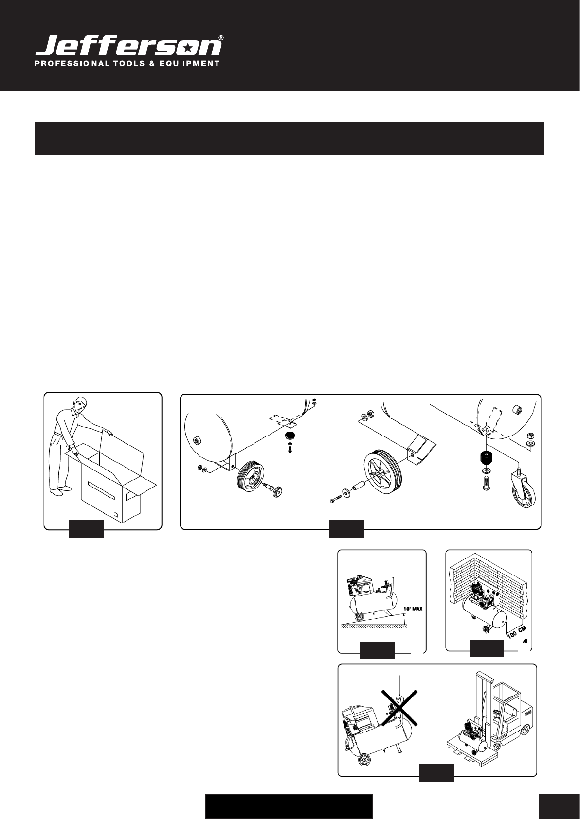
Upon receipt of the compressor, ensure all components are present and have remained undamaged in transit..Retain the packing materials and
packaging in case future transportation of the compressor is necessary. We recommend that the packaging is kept, at least within the period of
the guarantee (Fig.1).
WHEELS AND ANTI-VIBRATION FOOT
Pass the 15mm bolt through the wheel, the compressor's frame and secure with the 15mm nut. Press the rubber anti-vibration foot into the front
position. Locate the wheel onto the axle and secure in place with the internal self locking washer (single use only) (Fig.2).
AIR FILTER
If not already tted, remove the transit bung from the top of the head and screw the air lter assembly into position.
OIL BREATHER
• For transportation purposes the oil breather is supplied in a separate bag.
• Read the caution plate and take off the plastic bung from the crankcase, add oil and then assembly the oil breather.
• The plastic bung should be retained for future use should it be necessary to transport the unit.
WARNING:
Never operate the compressor with only the plastic transportation bung tted. Under normal use internal pressure can expel the bung along with
oil from the head, possibly leading to damage.
PLEASE NOTE THE FOLLOWING PHOTOGRAPHS & INSTRUCTIONS ARE FOR REFERENCE ONLY AND MAY DIFFER FOR YOUR
COMPRESSOR MODEL. PLEASE CONTACT JEFFERSON TOOLS IF YOU NEED ANY ADVICE ON THE ASSEMBLY PROCEDURE.
Position the compressor on a at surface or with a maximum permissible
inclination of 10° (Fig.3), in a well aired place, protected against atmospheric
agents and not in a place subject to explosion hazard.
If the surface is inclined and smooth, check if the compressor moves while in
operation – if it does, secure the wheels with two wedges.
To ensure good ventilation and efcient cooling, the compressor must be
positioned at least 100cm from any wall (Fig. 4).
Ensure that the compressor is transported correctly, do not overturn it or lift it
with hooks or ropes (Fig. 5).
The packaging materials (cardboard, plastic bags, polystyrene, etc), must be
disposed of in an appropriate manner and recycled where possible.
These materials must not be left within the reach of children as they are potential
sources of danger.
UNPACKING & ASSEMBLY
Fig.3 Fig.4
Fig.2Fig.1
Fig.5
USER MANUAL
JEFC050V10B-230
50L V-PUMP AIR COMPRESSOR •3HP •10Bar •Direct Drive
www.jeffersontools.com
6
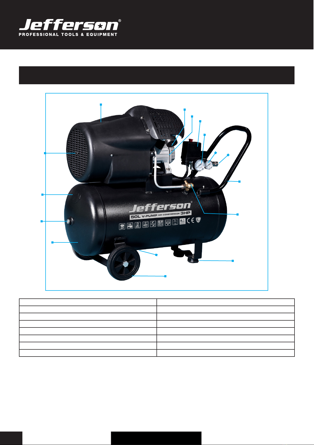
1. Air Tank 9. Tank Pressure Gauge
2. Socket Head Plug 10. Working Pressure Gauge
3. Pressure Tank 11. Air Outlet
4. Air Vents 12. Handle
5. Protective Cover 13. Non-Return Check Valve
6. Air Filter 14. Rubber Feet
7. Pump & Motor Assembly 15. Tank Drain Valve
8. Pressure Switch (ON/OFF) 16. Rear Wheels
EQUIPMENT IDENTIFICATION
3
2
1
4
5
7
6
8
9
10
12
11
13
14
16
15

USER MANUAL
JEFC050V10B-230
50L V-PUMP AIR COMPRESSOR •3HP •10Bar •Direct Drive
www.jeffersontools.com 7
Check oil Level:
Before using the compressor check the oil level
using the dipstick. If the oil is not up to the mark it
should be topped up with Jefferson HT68
Compressor oil (see Fig.6).
Sight glass / Oil Level:
The compressor oil level can be viewed through the
sight glass; the compressor must be on a level
surface to measure the oil level through the sight
glass accurately (see Fig.7):
• The top of the red dot indicates the full mark
• The bottom of the red dot indicates the low mark
Important: Always ensure that the oil level is correct before operating the compressor.
Ensure working environment is suitable for use:
This compressor must be used on a at, level surface The maximum safe operating angle
in any direction is 15° degrees (see Fig.8).
• Do not operate the compressor on inclines in excess of 15° degrees.
• Serious damage to pump components may result from insufcient lubrication.
• Never use the air compressor on a rooftop or elevated position that could allow the
unit to fall or be tipped over.
• Use additional air hose for elevated jobs.
Check power supply is correct for this compressor:
It is essential that the air compressor has an adequate power supply.
Always utilize more air hose before choosing to use an extension lead, as low voltage could cause
damage to the motor. (Low voltage damage is not covered under warranty)
Read and understand all the electrical safety guidelines laid out in this manual, follow all applicable local authority safety guidelines.
BEFORE FIRST USE
Fig.6 Fig.7
Fig.8

USER MANUAL
JEFC050V10B-230
50L V-PUMP AIR COMPRESSOR •3HP •10Bar •Direct Drive
www.jeffersontools.com
8
Read and ensure that you understand all of the operating instructions, safety precautions and warnings in this Instruction
Manual before operating or maintaining this compressor. Most accidents that result from compressor operation and
maintenance are caused by the failure to observe basic safety rules or precautions. An accident can often be avoided by
recognizing a potentially hazardous situation before it occurs, and by observing appropriate safety procedures. Hazards
that must be avoided to prevent bodily injury or machine damage are identied by warnings on the compressor and in this
Instruction Manual. Never use this compressor or modify it in any way that has not been specically recommended by the
manufacturer. Contact a qualied electrician for advice on any issues relating to electrical safety in your working environment.
ELECTRICAL SAFETY
Ensure that you check the equipment thoroughly to ensure it is safe and t for purpose before each use. It is important that
you inspect all plugs, sockets, power cables and electrical ttings for wear and damage and repair or replace any defective
components. The risk of electric shock can be minimised by the correct use of the appropriate electrical safety devices.
• We recommend that you t a Residual Current Circuit Breaker (RCCB) in the main distribution board and that a Residual Current Device
(RCD) is used when operating this equipment.
• The Electricity at Work Act 1989 includes legislation that places legal implications on employers to ensure the safety of electrical devices
in the workplace. The regulations dictate that all portable equipment must be inspected regularly and tested to ensure that it is safe for use.
'Portable equipment' means any electrical item that can be moved and this is often referred to as Portable Appliance Testing (PAT). PAT
testing should be carried out regularly on this equipment by trained, authorised personnel, as required by the legislation.
• The Health and Safety at Work Act 1974 states that it is the responsibility of the owner of electrical appliances to ensure that both the
equipment and working environments are maintained to ensure safe operation at all times.
• Check that all equipment cables are secure, correctly insulated, free from damage, and protected against short circuit and overload before
connecting to the power supply. Do not use worn or damaged cables, plugs, sockets or other ttings.
• Ensure that the power supply matches voltage requirements specied on the equipment and that the plug is wired correctly and tted with
the correct fuse.
• If the electrical fuse blows, ensure it is replaced by an identical type of fuse with the same rating.
• Never pull or manoeuvre this equipment into position using the power cable (move using the handle).
• Ensure the power cable is kept away from heat, oil and sharp edges.
• We recommend that the equipment is connected directly to the power supply without the use of extension leads as the resulting voltage drop
can reduce motor and pump performance.
• Always disconnect the compressor from the power source and remove the compressed air from the air tank before servicing, inspecting,
maintaining, cleaning, replacing or checking any parts.
• Do not carry the compressor while it is connected to its power source or when the air tank is lled with compressed air. Be sure the pressure
switch is in the “Off” position before connecting the compressor to its power source.
• Do not use the compressor in damp / wet conditions.
SAFETY GUIDELINES

USER MANUAL
JEFC050V10B-230
50L V-PUMP AIR COMPRESSOR •3HP •10Bar •Direct Drive
www.jeffersontools.com 9
EQUIPMENT SAFETY
• Never place your hands, ngers or other body parts near the compressor’s moving parts during operation. Ensure that the equipment is
isolated from the power supply and all switches in the OFF position before carrying out maintenance, repairs or adjustments.
• Never operate this compressor without all guards or safety features in place and in proper working order. If maintenance or servicing requires
the removal of a guard or safety features, be sure to replace the guards or safety features before resuming operation of the compressor.
• Always wear safety goggles or equivalent eye protection. Compressed air must never be aimed at anyone or any part of the body.
• When not in use, the compressor should be stored in dry place. Keep out of reach of children. Keep children and animals away from the work
area.
• Clear all work areas of unnecessary tools, debris, furniture etc. prior to use. Cluttered work areas can lead to injuries.
• Do not wear loose clothing or jewellery when operating this equipment. They can be caught in moving parts. Wear protective hair covering to
contain long hair.
• Follow instructions for lubricating this equipment as required.
• Watch what you are doing and remove any potential distractions before use. Use common sense at all times.
• Do not operate this equipment when you are tired or if you are under the inuence of alcohol, drugs or medication that makes you drowsy.
• Check for the correct alignment of moving parts, binding of moving parts, condition of parts, mounting, and air leaks, and any other issues
that might affect the safe operation of this equipment. A guard or other part that is damaged should be properly repaired or replaced by
an authorized Jefferson service centre unless otherwise indicated elsewhere in this instruction manual. Have defective pressure switches
replaced by an authorized service centre. Do not use compressor if the switch does not turn it on and off.
• Operate the compressor according to the instructions provided in this manual. Never allow the compressor to be operated by children,
individuals unfamiliar with its operation or unauthorized personnel.
• Keep all screws, bolts, and plates tightly mounted. Check regularly.
• The motor air vent must be kept clean so that air can freely ow at all times. Check for dust build-up frequently and clean as required.
• If the equipment appears to be operating unusually, making strange noises, or otherwise appears defective, stop using it immediately and
arrange for repairs by a authorized service centre.
• Solvents such as petrol, thinner, benzine, carbon tetrachloride, and alcohol may damage and crack plastic parts. Do not wipe them with such
solvents. Wipe plastic parts with a soft cloth lightly dampened with soapy water and dry thoroughly.
• Only use Jefferson approved replacement parts. Non-approved parts will void your warranty and can lead to malfunction and resulting
injuries. Genuine parts are available from Jefferson your dealer.
• Do not modify the compressor for any use other than which it was designed for by the manufacturer. Do not tamper with or attempt to adjust
the tank, pressure switch or safety valve. Never strap anything to the tank. Do not subject the tank to impact, vibration, heat, abrasion or
corrosive materials.
• Always contact an authorized service centre for advice on any repairs. Unauthorized modication may not only impair the compressor
performance but may also result in accident or injury to repair personnel who do not have the required knowledge and technical expertise to
perform the repair operations correctly.
• When the compressor is not in use, ensure the pressure switch is turned off, disconnect the equipment from the power source and open the
drain cock to discharge the compressed air from the air tank.
• To reduce the risk of burns, do not touch tubes, heads, cylinder and motors. During or immediately after use. Allow equipment to cool down
before carrying out maintenance, repairs or adjustments.
• Never direct the output jet of air at persons or animals. Ensure air supply valve is turned OFF before disconnecting the air supply hose.
• Read the all safety instructions for any tool or accessory used with the compressor and ensure the safe working pressure of any appliance
used exceeds the output pressure of the compressor. If you are using a spray gun it is important to ensure that the work area has sufcient
ventilation in place.
• Do not operate in the vicinity of ammable liquids, gases or solids.
• Do not operate the compressor without an air lter or restrict the air ow around the equipment.
• When the compressor is not in use ensure that it is switched off, disconnected from the power supply and the air and moisture drained from
the tank.

USER MANUAL
JEFC050V10B-230
50L V-PUMP AIR COMPRESSOR •3HP •10Bar •Direct Drive
www.jeffersontools.com
10
OPERATION GUIDE
WARNING: Take care when selecting tools for use with the compressor. Air tool manufacturers normally express the volume of air required to
operate a tool in cubic feet per minute (cfm). This refers to free air delivered by the compressor (‘air out’) which varies according to the pressure
setting. Do not confuse this with the compressor displacement which is the air taken in by the compressor (‘air in’). ‘Air out’ is always less than ‘air
in’ due to losses within the compressor.
Starting The Compressor:
Before starting the compressor check that the Pressure / ON/OFF switch is in the “OFF” position, the regulator tap is closed, the output gauge
must read Zero ‘0’ bar.
Plug mains lead into mains supply and start the compressor by moving the main switch to the ‘ON’ position.
The pressure switch automatically controls the power to the motor. It also allows for manual operation via the Push/Pull - On/Off switch on top of
the pressure switch.
Use the Pressure Switch controls to turn the compressor "ON/OFF". The Pressure Switch is a push/pull switch type. To turn the compressor ‘ON’
pull the switch knob upwards. To turn the compressor 'OFF’ push the knob downwards.
The pressure switch is factory set to turn the compressor on when the tank pressure drops below 85 psi and turn itself off again when the tank is
full.
Note: When starting the compressor for the first time, leave it running with no air tools connected to the air outlet. Make sure that pressure in
the tank rises and that the compressor stops automatically when the maximum pressure is reached - this information is indicated on the data
specification plate and shown on the pressure gauge.
The compressor will now operate automatically. The pressure switch stops the motor when the maximum tank pressure is reached and restarts it
when the pressure falls below the minimum threshold - approx. 2 bar (29psi) less than the maximum pressure.
Stopping The Compressor:
Stop the compressor by moving the main switch to the ‘OFF ‘position. The compressed air inside the compressor head will ow out, making the
restart easier and preventing the motor from being damaged.
DO NOT, other than in an emergency, stop the compressor by switching off the mains socket, or by pulling the plug out, as the pressure relief will
not then operate and motor damage may result upon restart.
When the compressor runs correctly and is stopped correctly there will be:
(1) a whistle of compressed air when the motor stops,
(2) a protracted whistle (about 20-25 seconds) when the compressor starts with no pressure in the tank.
Regulating The Pressure:
The output pressure is regulated by the pressure regulator. Lift and turn the knob clockwise to increase pressure and anticlockwise to reduce
it - push knob down to lock in required position. To determine the correct working pressure for any piece of equipment check the corresponding
manual for your tool.
When the compressor is not being used set the regulated pressure to zero so as to avoid damaging the pressure regulator.
WARNING: If the motor does not cut in and out, but runs continuously when using an air appliance, the capacity of the compressor may be too
small for the equipment or tool.
The gauge indicates the pressure inside the main tank, NOT the pressure supplied to the air equipment. Should the pressure in the main tank
exceed the pre-set switch maximum, a safety valve will activate.
For this reason DO NOT tamper with, or adjust, the switch or safety valve.
When the compressor is not in use, it should be switched off, disconnected from the mains supply and the air drained from the tank.
USER MANUAL
JEFC050V10B-230
50L V-PUMP AIR COMPRESSOR •3HP •10Bar •Direct Drive
www.jeffersontools.com 11
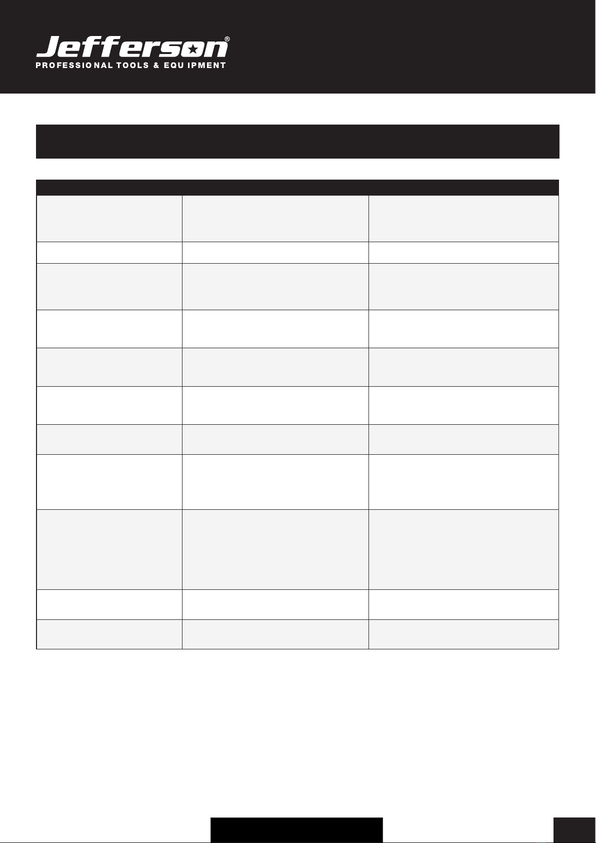
TROUBLESHOOTING
FAULT CAUSE REMEDY
Tank pressure drops continually. Air leak, check all connections. Locate and rectify leak. Run the compressor at maximum
pressure then switch off and disconnect. Brush a soapy
water solution over the connections and look for bubbles.
Tighten any connections showing leaks. If problem
persists contact your authorised service agent.
Tank pressure won’t build up. The drain valve is open. Close the tank drain valve.
The compressor won’t switch off.
The safety valve blows off.
Compressor does not stop when maximum
pressure is reached.
Pressure switch fails to stop motor. Faulty pressure
switch.
Contact your authorised service agent.
Tank pressure won’t build up and the pump
is getting hotter than normal, inlet suction
is poor.
The compressor head gasket or valve plate is faulty.
Fault with the air lter.
Contact your authorised service agent.
Check, clean, replace air lter as required.
There is a leak from the base of the
pressure switch when the compressor is
running.
Failure of the pressure relief valve. (Located in the base
of pressure switch).
Contact your authorised service agent.
There is a leak from the base of the
pressure switch when the compressor is
stopped.
The Non-return valve (from the tank) is leaking. Disassemble and clean, if necessary replace valve insert.
Contact your authorised service agent.
The compressor is noisy with metallic
clangs / knocks.
Bearing or piston problem.
Low oil level.
Stop the compressor and contact a specialized service
technician.
The compressor sounds like it is trying to
start (motor makes a humming noise).
Air pressure trapped on piston is resisting the starting
effort.
Faulty capcitor or fault within the electric motor.
Turn unit off and on again using the pressure switch. This
will vent air from the delivery tube.
Stop the compressor and contact a specialized service
technician.
Overload switch activated. Startup load may have activated overload switch.
Extension lead is too long (if in use).
Head unloader not functioning.
Leave for a few minutes then press the reset button and
restart.
Remove the extension lead and test compressor by
connecting the compressor as close to the main fuse box
as possible.
Stop the compressor and contact a specialized service
technician.
Air leaks from the safety valve at pressures
less than 8 bar.
The safety valve is faulty. Replace the safety valve.
Compressor stops and will not restart. Power failure.
Motor Failure.
Check electrical supply and fuse.
Contact your authorised service agent.

USER MANUAL
JEFC050V10B-230
50L V-PUMP AIR COMPRESSOR •3HP •10Bar •Direct Drive
www.jeffersontools.com
12
MAINTENANCE
Before attempting any maintenance jobs on the compressor, make sure of the following:
1. The master power switch is tuned off and equipment is isolated from the mains supply.
2. Pressure switch and the control unit switches are all in the OFF position.
3. All pressure has been removed from the air tank.
Procedure Daily / Weekly 100Hrs 200Hrs 400Hrs
Check pump oil level •
Drain condensate water from the tank •
Check for unusual noise and vibration •
Inspect equipment for air leaks •
Check air filters •
Replace air filters •
General cleaning •
Check safety relief valve •
Check belts for wear / replace •
Check and tighten all bolts •
Check tubes fittings & electrical connections •
Service pump / engine •
Internal & external tank inspection •
Replace the oil •
Changing / Filling Compressor Pump Oil
• Ensure the compressor is turned off and disconnected from the power source.
• Allow the compressor pump and other parts to cool off (if changing oil after use).
• Ensure compressor is on a at and level surface.
• Remove ll cap / plug and place collection container underneath the oil drain cap.
• Remove the oil drain cap, and let the oil drain out.
• Replace the oil cap and be sure to tighten this nut securely (you can use some PTFE tape on the thread to help create a tighter seal before
tightening).
• Fill the oil reservoir with a compatible compressor oil (e.g Jefferson HT68 Compressor Oil).
Checking / Cleaning the Air Filter
• Ensure the compressor is turned off and disconnected from the power source.
• Allow the compressor pump and other parts to cool off (if changing lter after use).
• Unscrew the lter top from the lter base by turning (generally) counter-clockwise (the direction may vary depending on your lter).
• Separate the lter top cover from the base.
• Remove the lter element from the lter base.
• Blow out dust and debris from the lter element.
• Replace air lter element if required.
• Reconnect lter top to the base and secure lter.

USER MANUAL
JEFC050V10B-230
50L V-PUMP AIR COMPRESSOR •3HP •10Bar •Direct Drive
www.jeffersontools.com 13
WEEE Waste Electrical and Electronic Equipment Statement
Information on Disposal for Users of Waste Electrical & Electronic Equipment
This symbol on the product(s) and / or accompanying documents means that used electrical and electronic products should
not be mixed with general household waste. For proper treatment, recovery and recycling, please take this product(s) to
designated collection points where it will be accepted free of charge.
For private households:
Dispose of this product at the end of its working life and in compliance with the EU Directive on Waste Electrical and Electronic
Equipment (WEEE). Contact your local solid waste authority for recycling information for this equipment.
Disposing of this product correctly will help save valuable resources and prevent any potential negative effects on human health and the
environment, which could otherwise arise from inappropriate waste handling.
Please contact your local authority for further details of your nearest designated collection point.
Penalties may be applicable for incorrect disposal of this waste, in accordance with you national legislation.
For business users in the European Union:
If you wish to discard electrical and electronic equipment, please contact your dealer or supplier for further information.
Information on Disposal in other Countries outside the European Union:
This symbol is only valid in the European Union. If you wish to discard this product please contact your local authorities or dealer and ask for the
correct method of disposal.
RoHS Directive 2011/65/EU
We hereby declare that this equipment has been tested and found to be compliant to RoHS Directive 2011/65/EU of the European Parliament and
the Council from 08/06/2011 on restriction of the use of certain hazardous substances in electrical and electronic appliances.
Determination of levels of regulated substances in electrotechnical products, elements of Cadmium (Cd), Lead (Pb), Mercury (Hg), Chromium (Cr)
and Bromine (Br) contents were measured by XRF Spectroscopy and chemical conrmation test for RoHS restricted substances.
ENVIRONMENTAL PROTECTION
Recycle any packaging and unwanted materials instead of disposing of them as waste. All tools, accessories and packaging
should be sorted, taken to a recycling centre and disposed of in a manner which is compatible with the environment.
When the product becomes completely unserviceable, reaches the end of its working life and requires disposal, drain off any
uids (if applicable) into approved containers and dispose of the product and the uids according to local regulations.
USER MANUAL
JEFC050V10B-230
50L V-PUMP AIR COMPRESSOR •3HP •10Bar •Direct Drive
www.jeffersontools.com
14
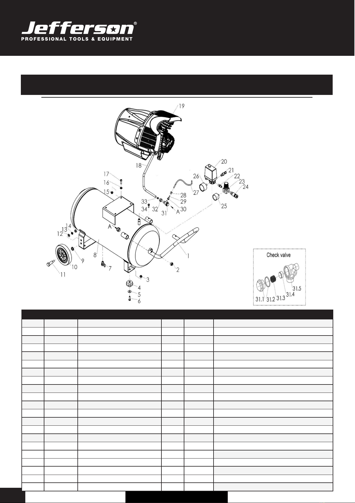
PARTS LIST & DIAGRAM - MAIN ASSEMBLY
# Quantity Description # Quantity Description
11 Handle 20 1 Pressure Switch
22 Socket Head Plug 21 1 Safety Valve
32 Hex Nut 22 1 Nipple
42 Rubber Pad 23 1 Pressure Regulator
52 PL.Washer 24 1 Quick Coupler
62 Hex Bolt 25 1 Pressure Gauge
71 Drain Valve 26 1 Pressure Gauge
81 Air Tank 27 1 Discharge Tube
92 Wheel Gasket 28 1 Sleeve Nut
10 2 Wheel 29 2 Bushing
11 2 PL. Washer 30 2 Sleeve
12 2 PL. Washer 31 1 Check Valve
13 2 SP. Washer 31.1 1 Bonnet
14 2 Hex Nut 31.2 1 O-ring
15 4 Hex Nut 31.3 1 Spring
16 4 SP. Washer 31.4 1 Valve Element
17 4 Hex Socket Screw 31.5 1 Valve Body
18 1 Aluminium Tube 32 2 Sleeve Nut
19 1 Pump / Motor Assembly 33 2 Sleeve
34 2 Hex Bolt

USER MANUAL
JEFC050V10B-230
50L V-PUMP AIR COMPRESSOR •3HP •10Bar •Direct Drive
www.jeffersontools.com 15
PARTS LIST & DIAGRAM - PUMP ASSEMBLY
# Qty Description # Qty Description # Qty Description
11 Oil sightglass 19 4 Scraping Ring 37 2 Hex Nut
21 O-Ring 20 2 Cylinder 38 2 SP Washer
34 Hex.bolt 21 4 Location Pin 39 2 Capacitor
41 Front cover 22 2 Gasket Valve 40 1 Stator Assembly
51 Breather 23 2 Blade, Valve 41 1 Rotor Assembly
61 Gasket 24 2 Valve Plate 42 1 Hex Socket Bolt
71 Hex.Socket bolt 25 2 Valve Holder 43 1 Centrifugal Switch
81 PL. washer 26 1 Air Filter Assembly 44 1 Bearing
91 Crankshaft 27 3 Cylinder Head 45 1 Rear Cover
10 1 Hex.Socket bolt 28 8 Hex Bolt 46 3 Hex Socket Bolt
11 1 Crank case 29 1 Hex Bolt 47 1 Plastic Tray
12 4 Hex.Socket bolt 30 1 Hex Bolt 48 1 Fan Blade
13 2 Cylinder gasket 31 1 2-Way Manifold Nipple 49 1 Circlip
14 2 Connecting rod 32 1 3-Way Manifold Nipple 50 1 Bow Cap
15 4 Circlip 33 1 Copper Tube 51 1 Shroud
16 2 Piston pin 34 1 Oil Seal 52 4 SP Washer
17 2 Piston 35 1Bearing 53 4 Philips Head Screw
18 2 Oil ring 36 1Plastic Tray 54 3 Philips Head Screw
USER MANUAL
JEFC050V10B-230
50L V-PUMP AIR COMPRESSOR •3HP •10Bar •Direct Drive
www.jeffersontools.com
16
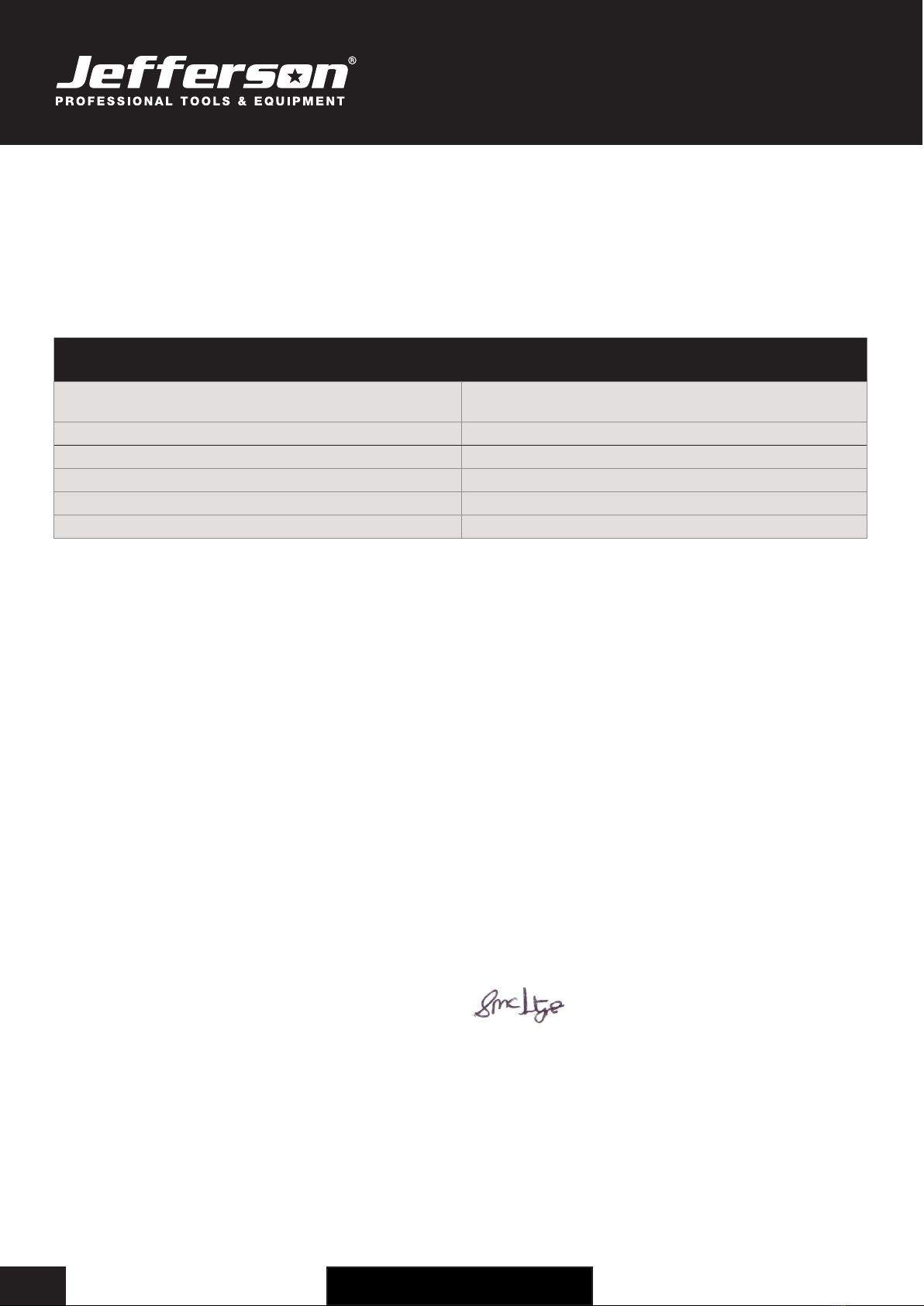
EC Declaration of Conformity
We, Jefferson Professional Tools & Equipment, as the authorised European
Community representative of the manufacturer, declare that the following equipment
conforms to the requirements of the following Directives:
Directive: Description:
2000/14/EC (as amended) Noise Emission in the Environment by
Equipment for Use Outdoors
2014/30/EU (as amended) Electromagnetic Compatibility
2006/42/EC (as amended) Machinery Directive
2014/29/EU (as amended) Simple Pressure Vessels Directive
2014/35/EU (as amended) Low Voltage Directive
2011/65/EU (as amended) RoHS Directive
Equipment Category: Air Compressor (Item 8)
Product Name/Model: JEFC050V10B-230
50L 3HP 10 Bar V-Pump Air Compressor
Notified Body: Technicka inspekcia a.s. Trnavska cesta 56
821 01 BRATISLAVA
Country : Slovakia
Phone : +421 2 49 208 100
Fax : +421 2 49 208 160
Notified Body Number: 1354
Measured Sound Power Level: 96dB (LWA)
Guaranteed Sound Power Level: 96dB (LWA)
Signed by: Stephen McIntyre
Position in the company: Operations Director
Date: 24 January 2019
Name and address of manufacturer
or authorised representative:
Jefferson Tools, Herons Way, Chester Business Park, Chester, United
Kingdom, CH4 9QR
Telephone: +44 (0)1244 646 048
Fax: +44 (0)1244 241 191
Email: [email protected]

USER MANUAL
JEFC050V10B-230
50L V-PUMP AIR COMPRESSOR •3HP •10Bar •Direct Drive
www.jeffersontools.com 17
Jefferson Professional Tools & Equipment, or hereafter "Jefferson" warrants its customers that its products will be free of defects in workmanship
or material. Jefferson shall, upon suitable notication, correct any defects, by repair or replacement, of any parts or components of this product
that are determined by Jefferson to be faulty or defective.
This warranty is void if the equipment has been subjected to improper installation, storage, alteration, abnormal operations, improper care, service
or repair.
Warranty Period
Jefferson will assume both the parts and labour expense of correcting defects during the stated warranty periods below.
All warranty periods start from the date of purchase from an authorised Jefferson dealer. If proof of purchase is unavailable from the end user, then
the date of purchase will be deemed to be 3 months after the initial sale to the distributor.
2 Years
• JEFC050V10B-230 - 50L 3HP 10 Bar V-Pump Air Compressor
90 Days
• All replacement parts purchased outside of the warranty period
Important: All parts used in the repair or replacement of warranty covered equipment will be subject to a minimum of 90 days cover or the
remaining duration of the warranty period from the original date of purchase.
Warranty Registration / Activation
You can register and activate your warranty by visiting the Jefferson Tools website using the following address:
www.jeffersontools.com/warranty and completing the online form. Online warranty registration is recommended as it eliminates the need to
provide proof of purchase should a warranty claim be necessary.
Warranty Repair
Should Jefferson confirm the existence of any defect covered by this warranty the defect will be corrected by repair or replacement at an
authorized Jefferson dealer or repair centre.
Packaging & Freight Costs
The customer is responsible for the packaging of the equipment and making it ready for collection. Jefferson will arrange collection and
transportation of any equipment returned under warranty. Upon inspection of the equipment, if no defect can be found or the equipment is not
covered under the terms of the Jefferson warranty, the customer will be liable for any labour and return transportation costs incurred.
These costs will be agreed with the customer before the machine is returned.
*Jefferson reserve the right to void any warranty for damages identified as being caused through misuse
Warranty Limitations
Jefferson will not accept responsibility or liability for repairs made by unauthorised technicians or engineers. Jefferson's liability under this
warranty will not exceed the cost of correcting the defect of the Jefferson products.
Jefferson will not be liable for incidental or consequential damages (such as loss of business or hire of substitute equipment etc.) caused by
the defect or the time involved to correct the defect. This written warranty is the only express warranty provided by Jefferson with respect to its
products.
Any warranties of merchantability are limited to the duration of this limited warranty for the equipment involved.
Jefferson is not responsible for cable wear due to flexing and abrasion. The end user is responsible for routine inspection of cables for possible
wear and to correct any issues prior to cable failure.
LIMITED WARRANTY STATEMENT

USER MANUAL
JEFC050V10B-230
50L V-PUMP AIR COMPRESSOR •3HP •10Bar •Direct Drive
www.jeffersontools.com
18
Claiming Warranty Coverage
The end user must contact Jefferson Professional Tools & Equipment (Tel: +44 (0) 1244 646 048) or their nearest authorised Jefferson dealer where
final determination of the warranty coverage can be ascertained.
Step 1 - Reporting the Defect
Online Method:
• Visit our website www.jeffersontools.com/warranty and complete the Warranty Returns form. You can complete the form online and submit it
to us directly or download the form to print out and return by post.
Telephone Method:
Contact your Jefferson dealer or sales representative with the following information:
• Model number
• Serial number (usually located on the specification plate)
• Date of purchase
A Warranty Returns form will be sent to you for completion and return by post or fax, together with details of your nearest authorised Jefferson
repair centre. On receipt of this form Jefferson will arrange to collect the equipment from you at the earliest convenience.
Step 2 - Returning the Equipment
It is the customer's responsibility to ensure that the equipment is appropriately and securely packaged for collection, together with a copy of
the original proof of purchase. Please note that Jefferson cannot assume any responsibility for any damage incurred to equipment during
transit. Any claims against a third party courier will be dealt with under the terms & conditions of their road haulage association directives.
Please note: Jefferson will be unable to collect or process any warranty requests without a copy of the original proof of purchase.
Step 3 - Assessment and Repair
On receipt, the equipment will be assessed by an authorised Jefferson engineer and it will be determined if the equipment is defective and in need
of repair and any repairs needed are covered by the warranty policy. In order to qualify for warranty cover all equipment presented must have been
used, serviced and maintained as instructed in the user manual.
Where repair is not covered by the warranty a quotation for repair, labour costs and return delivery will be sent to the customer (normally within 7
working days).
Note: If the repair quotation is not accepted Jefferson Professional Tools & Equipment will invoice 1 hour labour time at £30 per hour plus return
carriage costs (plus VAT).
In cases where no fault can be found with the equipment, or, if incorrect operation of the equipment is identified as the cause of the problem, a
minimum of 1 hour labour at £30 per hour plus carriage costs will be required before the equipment will be despatched back to the customer.
Any equipment repaired or replaced under warranty will normally be ready for shipment back to the customer within 7 working days upon receipt
of the equipment at an authorised Jefferson Repair centre (subject to part availability). Where parts are not immediately available Jefferson will
contact you with a revised date for completion of the repair.
General Warranty Enquiries
For any further information relating to Jefferson warranty cover please call +44 (0) 1244 646 048 or send your enquiry via email to warranty@
jeffersontools.com
Disclaimer:
The information in this document is to the best of our knowledge true and accurate, but all recommendations or suggestions are made without
guarantee. Since the conditions of use are beyond their control, Jefferson Tools® disclaim any liability for loss or damage suffered from the use of
this data or suggestions. Furthermore, no liability is accepted if use of any product in accordance with this data or suggestions infringes any patent.
Jefferson Tools® reserve the right to change product specifications and warranty statements without further notification. All images are for
illustration purposes only.


USER MANUAL
JEFC050V10B-230
50L V-PUMP AIR COMPRESSOR •3HP •10Bar •Direct Drive
www.jeffersontools.com
20
Jefferson Tools,
Herons Way,
Chester Business Park,
Chester,
United Kingdom,
CH4 9QR
Tel. +44 (0)1244 646 048
Email: [email protected]
IMPORTANT! SAFETY FIRST!
Before attempting to use this product please read
all the safety precautions and operating instructions
outlined in this manual to reduce the risk of fire,
electric shock or personal injury.
www.jeffersontools.com
www.jeffersontools.com
Table of contents
Other Jefferson Air Compressor manuals

Jefferson
Jefferson JEFC050L10B-230 User manual

Jefferson
Jefferson JEFCIND270L-10.0 User manual

Jefferson
Jefferson JEFC200L10B-230 User manual

Jefferson
Jefferson JEFC025L08B Series User manual

Jefferson
Jefferson TANDEM JEFC270T10B-230 User manual

Jefferson
Jefferson JEFC050L08B Series User manual

Jefferson
Jefferson JEFC100V10B Series User manual
Popular Air Compressor manuals by other brands


Craftsman
Craftsman 919.165230 owner's manual

Gardner Denver
Gardner Denver ELECTRA-SCREW EBE DD Series Operating and service manual

BAE Audio
BAE Audio 10DC instruction manual

Komptec
Komptec KT-90A user manual

Chicago Pneumatic
Chicago Pneumatic CPS 185 PD7 Instruction book

Danfoss
Danfoss Turbocor TT-300 user manual


