manuals.online logo
Brands
  1. Home
  2. •
  3. Brands
  4. •
  5. Gardner Denver
  6. •
  7. Air Compressor
  8. •
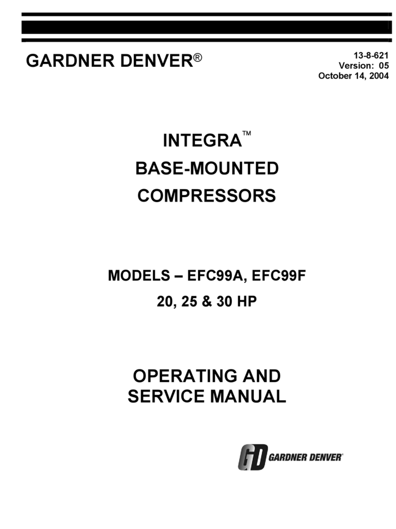
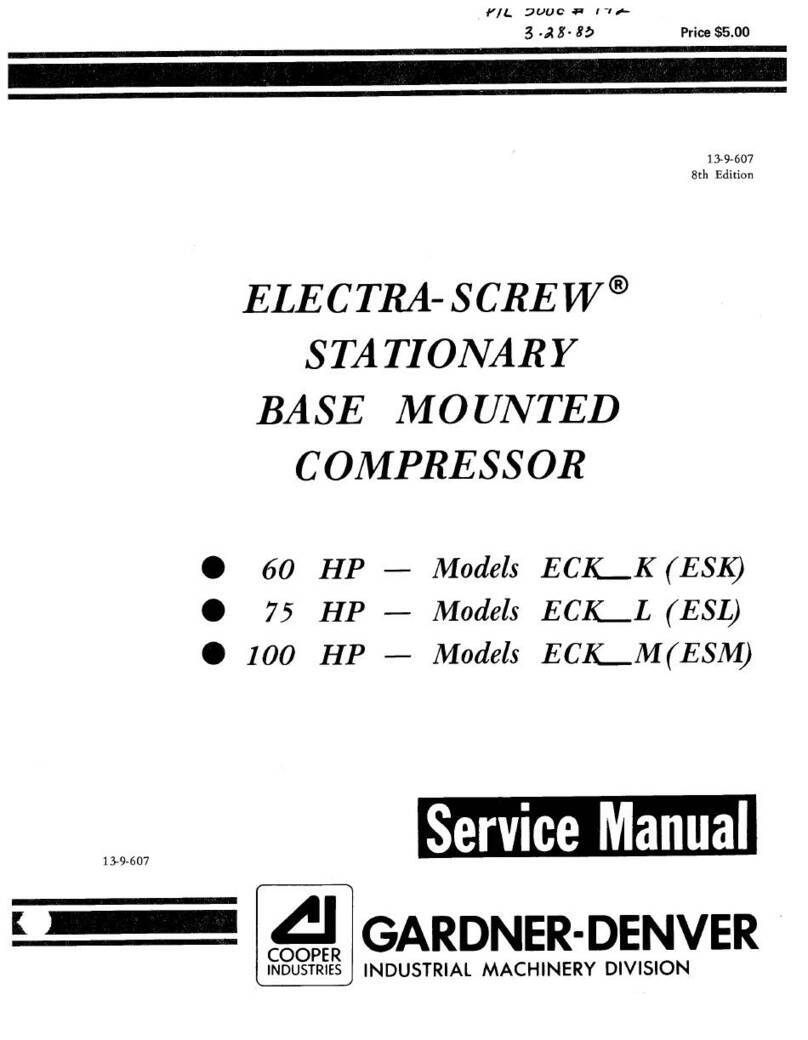
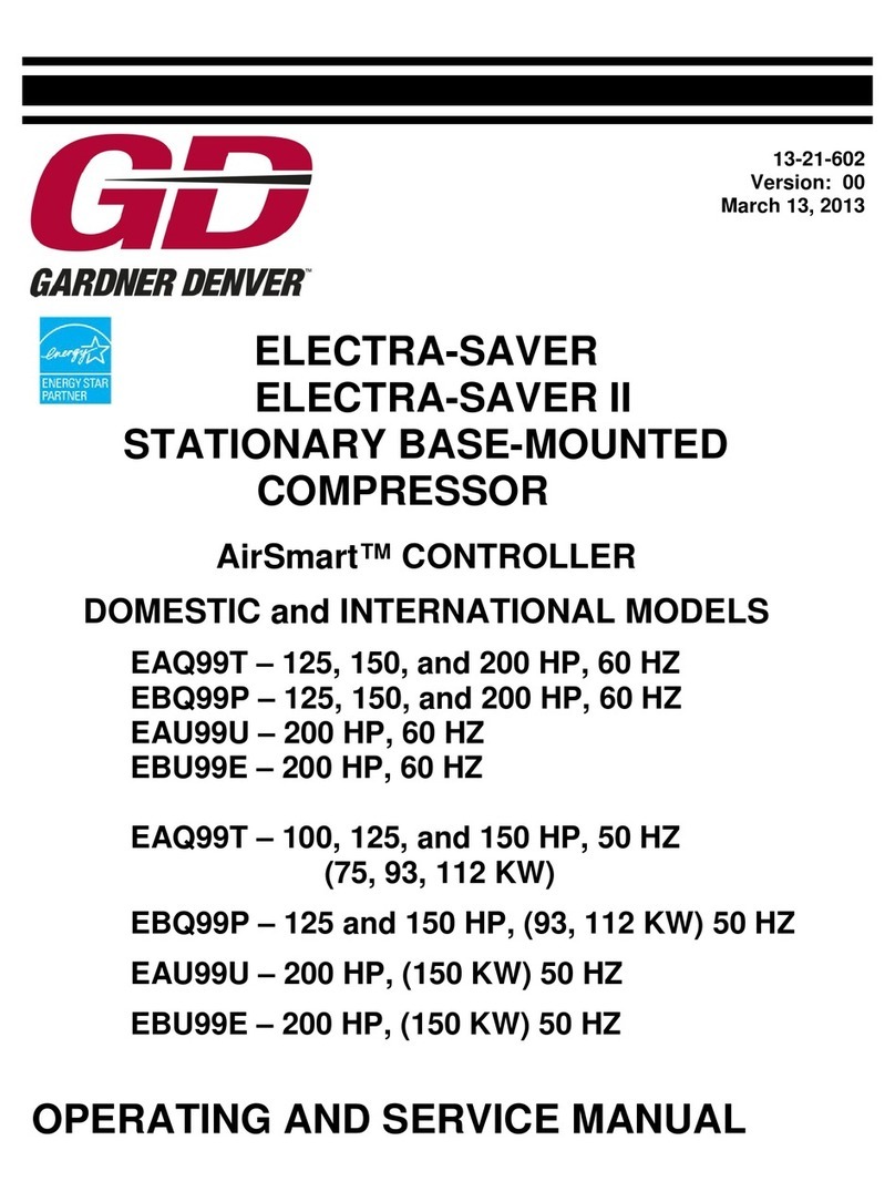
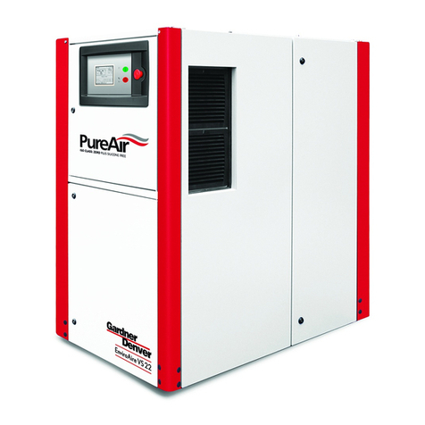
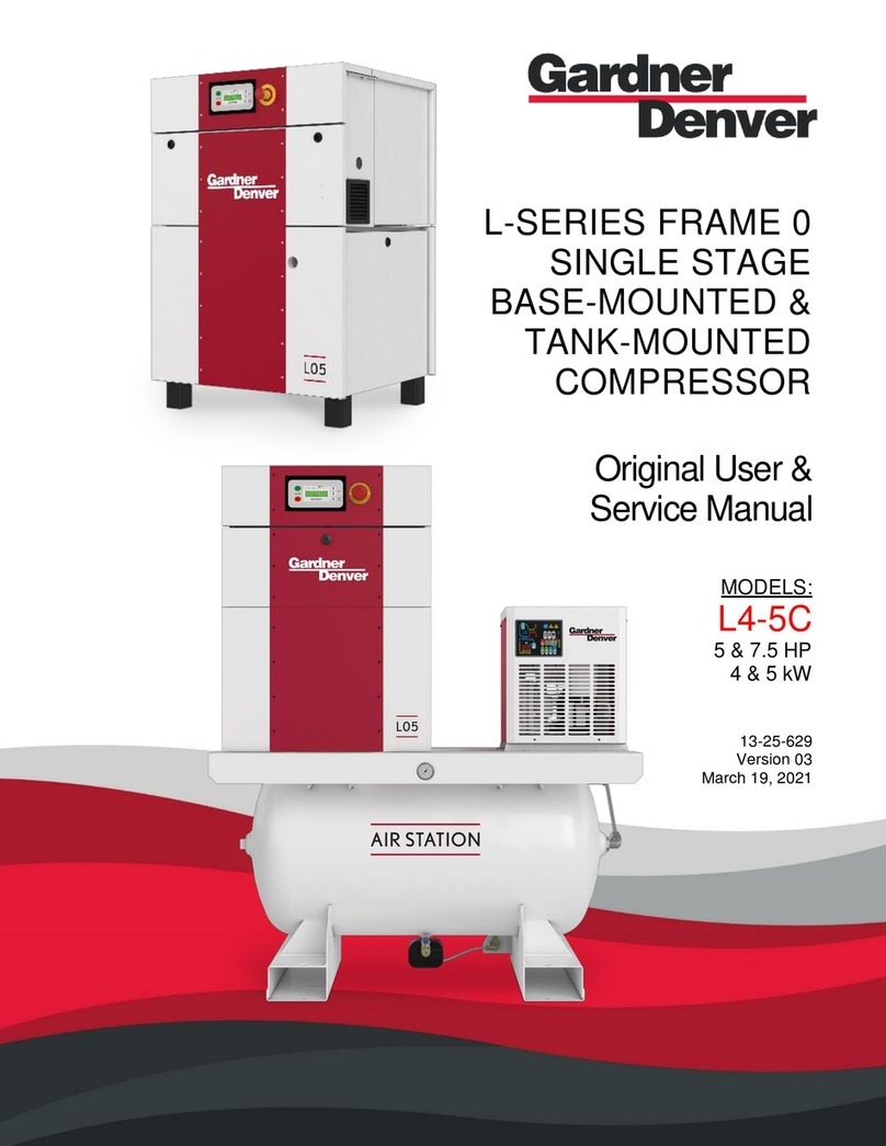
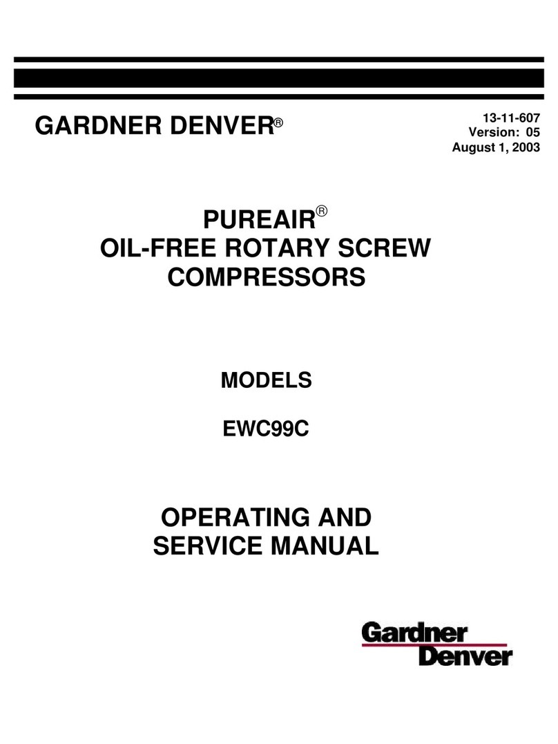
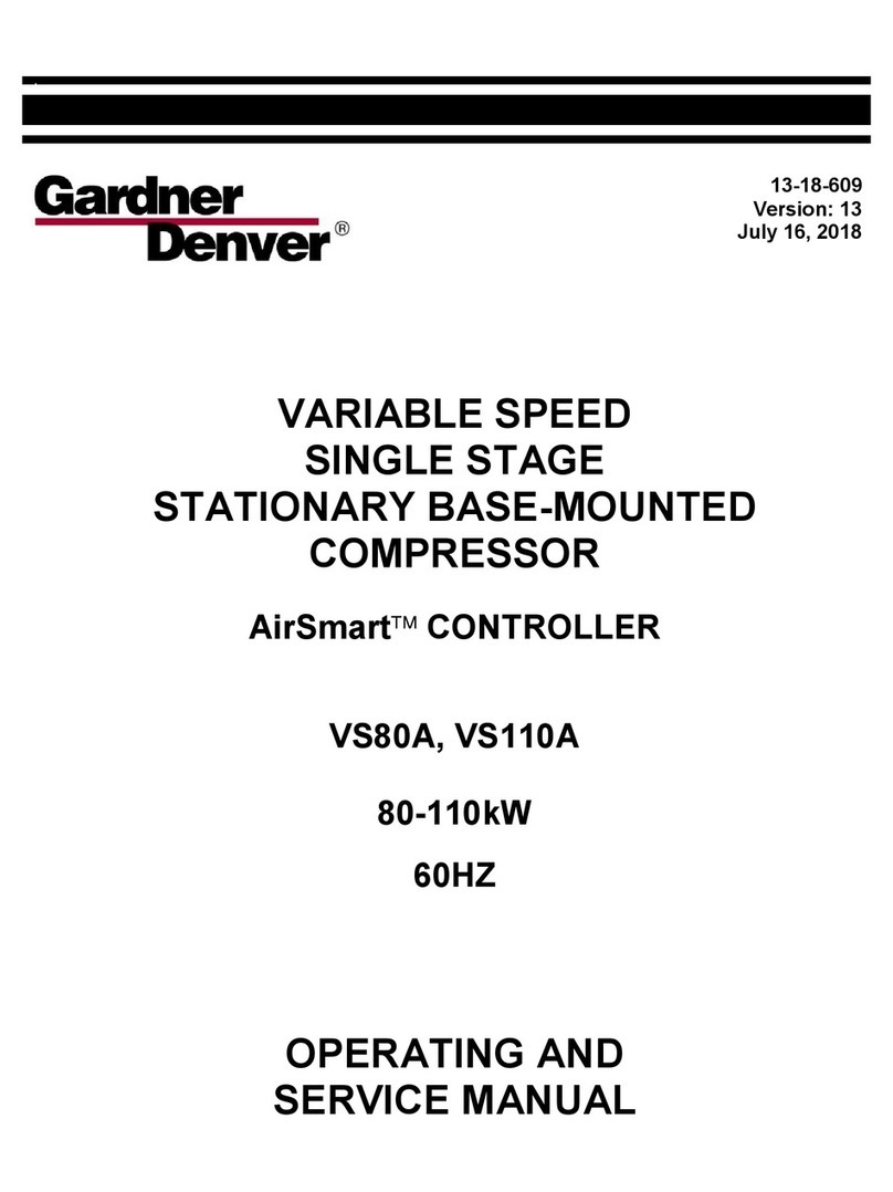
  9. Gardner Denver ELECTRA-SCREW EBE DD Series Service manual

Gardner Denver ELECTRA-SCREW EBE DD Series Service manual

GARDNER-DENVER” 13-8-609
1st Edition
ELECTRA-SCREW@ STATIONARY
BASE-MOUNTED &TANK-MOUNTED
COMPRESSORS
MODELS
EBE_DD -15 HP
EBE_ED -20 HP
EBE-_FD -25 HP
EBE_GD -30 HP
OPERATING AND
SERVICE MANUAL
●
COOPER
Gardner-Denver
Industrial Machinery
MAINllUN COMPRESSORRELiABILllY AND PERFORMANCE M/Ill-l
GENUINE GARDNER-DENVER AND JOY COMPRESSOR
PARTS AND SUPPORT SERVICES
Gardner-Denver and Joy Compressor genuine
parts, engineered to original tolerances, are de-
signed for optimum dependability --- specifically
for Gardner-Denver and Joy compressor systems.
Design and material innovations are the result of
years of experience with hundreds of different
compressor applications. Reliability in materials
and quality assurance are incorporated in our
genuine replacement parts.
Your authorized Gardner-Denver and Joy Com-
pressor distributor offers all the backup you’ll
need. Aworldwide network of authorized distribu-
tors provides the finest product support in the air
compressor industry.
Your local authorized distributor maintains alarge
inventory of genuine parts and he is backed up for
emergency parts by direct access to the Gardner-
Denver Industrial Machinery Master Distribution
Center (MDC) in Memphis, Tennessee.
Your authorized distributor can support your
Gardner-Denver or Joy air compressor with these
services:
1. Trained parts specialiststo assist you inselect-
ing the correct replacement parts.
2. Factory warranted new and remanufactured
rotary screw air ends. Most popular model
remanufactured air ends are maintained in
stock at MDC for purchase on an exchange
basic with liberal core credit available for the
replacement unit.
3. Afull line of factory tested AEON mcompres-
sor lubricants specifically formulated for use in
Gardner-Denver and Joy compressors.
4. Repair and maintenance kitsdesigned with the
necessary parts to simplify servicing your
compressor.
Authorized distributor service technicians are
factory-trained and skilled in compressor main-
tenance and repair. They are ready to respond
and assist you by providing fast, expert main-
tenance and repair services.
For the location of your local authorized Gardner-Denver and Joy Air Compressor distributor refer
to the yellow pages of your phone directory or contact:
Distribution Center: Factory:
Gardner-Denver Gardner-Denver
Industrial Machinery Division Industrial Machinery Division
Master Distribution Center 1800 Gardner Expressway
5585 East Shelby Drive Quincy, IL 62301
Memphis, TN 38115 Phone: (217) 222-5400
Phone: (901) 363-6100 Fax: (217) 2235897
Fax: (901) 393-1095
FOREWARD
Gardner-Denver Electra-Screw@ compressors are the result of advanced engineering and skilled manufacturing. To
be assured of receiving maximum service from this machine the owner must exercise care in its operation and
maintenance. This book is written to give the operator and maintenance department essential information for
day-to-day operation, maintenance and adjustment. Careful adherence to these instructions will result in economical
operation and minimum downtime.
DANGER
Failure to observe aDANGER notice could result in injury to, or death of personnel.
1I
11
WARNING
Failure to observe aWARNING notice could result in damage to equipment.
CAUTION
CAUTION notices set forth general reminders of good safety practice, or direct
attention to unsafe practices.
NOTE
Information furnished in aNOTE will include general information or the highlights of
aprocedure.
This book covers the following models:
HP PSIG Air Cooled
15 100, 125 EBE_DD
20 100, 125, 150 EBE_ED
25 100, 125, 150, 175 EBE_FD
30 100, 125, 150, 175 EBE_GD
TABLE OF CONTENTS
GENERAL lNFORMATION ............................................................................................................................. SECTION 1
lNSTALMTION ............................................................................................................................................... SECTION 2
STARTING AND OPERATING PROCEDURES ............................................................................................. SECTION 3
CONTROLS AND INSTRUMENTS ................................................................................................................. SECTION 4
LUBRICATION, OIL COOLER, OIL FILTER AND SEPARATOR ................................................................... SECTION 5
AIR FILTERS .................................................................................................................................................. SECTION 6
BELT DRIVE .................................................................................................................................................... SECTION 7
MAINTENANCE SCHEDULE ....................................................... ................................................................. SECTION 8
TROUBLE SHOOTING ................................................................................................................................... SECTION 9
13-6-609 Page i
INDEX
NOTE: Numbers preceding dash are Section Numbers –Numbers following dash are Page Numbers
Air Control Components ..........................................4-2
Air Cooled Unit installation .......................................2.l
Air Filter Element Liie................................................6.2
Air Filter Element Servicing instructions ..................6-l
AIR FILTER (SECTION 6) .........................................6-1
Air Flow Quantity. .....................................................2-l
Air/Oil Flow Diagram .................................................5.l
Auto Sentry S-Auto Lag Button ..............................4-3
Auto Sentry S-Auto Lead Button ............................4-3
Auto Sentry S-Constant Run Button ......................4-3
Auto Sentry S-Control Pad Diagram ......................4-8
Auto Sentry S-Hourmeter .......................................4.3
Auto Sentry S-Keypad ............................................4-3
Auto Sentry S-Lead-Lag operation ........................4-6
Auto Sentry S-Programming and Set-Up
Instructions ..........................................................4.4
Auto Sentry S-Stop/Reset Button ..........................4-3
Basic information ......................................................l.l
BELT DRIVE (SECTION 7) .......................................7-1
Blowdown Valve Control ..........................................4.2
Blowdown Valve Piping ............................................2.3
Cold Weather Operation ...........................................2.2
CONTROLS AND INSTRUMENTS (SECTION 4) ....4-1
Decals .......................................................................l.5
Discharge Service tine .............................................2.3
Electrical Wring ........................................................2.4
Enclosure .................................................................2.2
Error Messages -Definitions ....................................4-4
Filling Oil Resetvoir ..................................................5.3
Foundation ...............................................................2.l
GENERAL INFORMATION (SECTION 1) ................1-1
High Temperature Operation ..................................5-1
High Temperature Shutdown ...................................4.l
Inlet Line ..................................................................2.3
Inlet Valve Control ....................................................4.2
INSTALLATION (SECTION 2) .................................2-1
instruments ...............................................................4.2
LED -Change Air Filter .............................................4.4
LED -Change Separator ..........................................4.4
LED -High NrTemperature .....................................4.3
LED -Motor Overload ...............................................4.3
Lifting Unit ................................................................2-1
Location ...................................................................2.l
Lubricant, Addition of Oil Between Changes ..........5-2
Lubricant, Changing Type of Oil..............................5-1
Lubricant, Draining and Cleaning System ...............5-3
Lubricant, Oil Specifications ....................................5-1
Lubricant Change Interval ........................................5-3
LUBRICATION, OIL COOLER, OIL FILTER &
SEPARATOR (SECTION 5) .................................5-1
MAINTENANCE SCHEDULE (SECTION 8) ............8-1
Minimum Pressure/Check Valve .............................4-2
Moisture in the Oil System ......................................5-3
Motor Lubrication ....................................................24
Motor Protection Devices .......................................4-1
Oil Cooler -Radiator Type .......................................5-4
Oil Filter.....................................................................5.4
Oil Level Gauge .......................................................5.3
Oil Reservoir .............................................................5.4
Oil Reservoir Drain ...................................................2-2
Oil Separator ............................................................5.5
Oil Separator -Pressure Differential Gauging .........5-5
Oil Separator -Removal ...........................................5-5
Oil System Check ................................................... 5-6
Operating Air Pressure Adjustment .........................4-6
Outline Drawings ...................................................... 1-2
Pressure and Temperature Digital Readouts ..........4-4
Prestart-Up instructions .................................?.........3-1
Protective Devices and Shutdown ..........................4-1
Regressing Interval ..................................................2.5
Relief Valve ...............................................................4.l
Safety Precautions .................................................. 1-4
Separator Differential Pressure Shutdown ..............4-1
STARTING &OPERATING PROCEDURES
(SECTION 3) .......................................................3.l
Starting The Unit, Cold .............................................3-2
Starting The Unit, Hot ...............................................3-2
Stopping The Unit ...................................................3.2
Subtractive Pilot .......................................................4.6
Thermostatic Mixing Valve ......................................5-4
TROUBLE SHOOTING (SECTION 9) .....................9-1
Wiring Diagram .........................................................4.9
13-8-609 Page ii
SECTION 1
GENERAL INFORMATION
FIGURE 1-1 -COMPRESSION CYCLE
COMPRESSOR -The Gardner-Denver@ comtxessor
is asingle stage, positive displacement rotary machine
using meshing helical rotors to effect compression. Both
rotors are supported between high capacity roller bear-
ings located outside the compression chamber. Single
width cylindrical roller bearings are used at the inlet end
of the rotors to carry part of the radial loads. Tapered
roller bearings at the discharge end locate each rotor
axially and carry allthrust loads and the remainder of the
radial loads.
COMPRESSION PRINCIPLE (Figure 1-1) -Compres-
sion is accomplished by the main and secondary rotors
synchronously meshing in aone-piece c~linder. The
main rotor has four (4) helical lobes 90 apart. The
secondary rotor has six (6) matching helical grooves 60°
apart to allow meshing with main rotor lobes.
The air inlet port is located on top of the compressor
cylinder near the drive shafl end. The discharge port is
near the bottom at the opposite end of the compressor
cy!inder. Figure 1-1 is an inverted view to show inlet and
discharge ports. The compression cycle begins as the
rotors unmesh at the inlet port and air is drawn into the
cavity between the main rotor lobes and the secondary
rotor grooves (A). When the rotors pass the inlet port
cutoff, air is trapped in the interiobe cavity and flows
axially with the meshing rotors (B). As meshing contin-
ues, more of the main rotor lobe enters the secondary
rotor grove, normal volume is reduced and pressure
increases.
v
Oil is injected into the cylinder to remove the heat of
compression and seal internal clearances. Volume re-
duction and pressure increase continues until the air/oil
mixture trapped in the interlobe cavity by the rotors
passes the discharge port and is released to the oil
reservoir (C). Each rotor cavity follows the same “fill-
compressdischarge’i cycle in rapid succession to pro-
duce adischarge airflow that iscontinuous, smooth and
shock free.
AIR FLOW IN THE COMPRESSOR SYSTEM (Figure
1-5) -Air enters the air filter and passes through the inlet
unloader valve and on into the compression chamber
where oil is injected into the air. After compression, the
air/oil mixture passes into the oil reservoir where most
of the entrained oil is removed by velocity change and
impingement and drops back into the reservoir. The air
and remaining oil then passes through piping and the
air/oil separator. The air then passes through the mini-
mum pressure/check valve, the aftercooler and the
moisture separator and into the plant air lines.
LUBRICATION, COOLING AND SEALING -Oil is
forced by air pressure from the oil reservoir through the
oil cooler, thermostatic mixing valve, and oil filter and
discharge intothe compressor main oilgallery. Apottion
of the oil is directed through internal passages to the
bearings, gears and shaft oil seal. The balance of the oil
is injected directly into the compression chamber to
remove heat of compression, seal internal clearances
and lubricate the rotors.
13-8-W9 Section 1Page 1
OIL SEPARATOR
OIL RESERVOIRFILLER
bE:~:E::”vE ST(RE-,
ERATOR
~TH[RM~ CONTROL
\‘+
(MIXING) VALVE
OIL FILTER
BY-PASSPIPING
OIL RESERVOIR
FIGURE 2-1
13-8-609 Section 1Page 2
OIL LEVEL SIGHT GAUGES
n“R “LTER~
STARTER/CONTROL
::::;;= \
RESERVOIR OIL DRAIN
FIGURE 3-1
13-8-609 Sectionl Page3
SAFETY PRECAUTIONS
Safety is everybody’s business and is based on your use of good common sense. All situations or circumstances
cannot always be predicted and covered by established rules. Therefore, use Your wst experience, watch out for
safety hazards and be cautious. Some general safety precautions are given below -
WARNING
Failure to observe these notices could result in damage to equipment.
●stoD the unit if any repairs or adjustments on or around the compressor are
required.
●Disconnect the comtxesso runit from its power source before working on
the unit -this machine is automatically controlled and may start at any time.
.An Excess Flow Valve should be on all compressed air supply hoses
exceeding 1/2 inch inside diameter. (OSHA Regulation, Section 1518.302)
●J)o not excee dthe rated maximum nressure value Sshown on the nameplate.
oDo not otI crate unit if safety devices are not operating properly. Check
periodically. Never bypass safety devices.
DANGER
Failure to observe these notices could result in injury to or death of personnel.
o~ee~ finaers and cIothina awa yfrom revolving fan, drive coupling, etc.
.Do not usethe air discharae from this unit for breathing -not suitable for
human consumption.
.Do not loosen or remove the oil filler plug, drain plugs, covers, the thermo-
static mixing valve or break any connections, etc. in the compressor air or
oil system until the unit is shutdown and the air pressure has been relieved.
.Electrical shock can and may be fatal.
●co mmesso runit must be arounded in accordance with the National Electri-
cal Code. Aground jumper equal in size to the equipment ground conductor
must be used to connect the compressor motor base to the unit base.
●Fan motors must remain arounded to the main base through the starter
mounting panel in accordance with the National Electrical Code.
●g~e nmain disco nnects witc tI before working on the control.
●Disco nnect the comm’esso runit from its power source before working on
the unit -this machine is automatically controlled and may start at any time.
13-8-609 Section 1Page 4
DECALS
OIscHARGE AIR USED foR
BREATHING WILL CAUSE
StVERf INJARY OR DEATH.
coNsuLT rILTRAr ION
SPECIALIST FOR
AOGiIIONAl flLTRATl@!l
AND TREATMENT [OUIPMINT
TO MtXT HIALIN ANO
SAfETY RIGIKAIIONS. mum
AIR ANO OIL UNDER PRCSSURf
WILL CAUS[ SEVERE PERSONAL
INJURY OR DEATH.
SHUTDOWN COMPRESSOR ANO
RELIEVE SYSTEM OF ALL
PR[SSURE BEFORC REMCVING
VALVCS. CAPS. PLUGS.
FIT TINGS.BOLTS ANO FILTERS.
,—
r
ADAINi@m
HIGH VOLTAGE.
ROTATING MACHINERY.
AIR ANO OIL
UNOEil PRESSURE.
IMPROPER MODIFICATION DO NOT MODIFY
OF COUIPMCNT WILL UNIT WITHOUT
CAUSE SEV[RE PERSONAL WRITTEN PERMISSION
INJURY OR DEATH. FROM MANUFACTURER.
—1
@i!!!!i!!!!
Q3iii
o
ROTATING MACHINERY CAN
CAUSE INJURY OR OEATH.
KCEP ALL GUAROS ANO
SAFETY OIVICES IN
PLACE.
UNIT CAN AUTOMATICALLY
RESTART.
CAN CAUSS PERSONAL IN.ARY
OR CtATIL
KNOW MODE Of OIW?ATION
SZfORE WORKING ON OR
NEAR THE MACHINt. —
13-8-609 Sectionl Page5
fLECTRICAL SHOCK FROM kwm!wm
‘MpROpER‘ROuNO’NGCAN-o
CAUSE INJURY OR DEATH.
GROUND UNIT AND llfLATCD
EQUIPMENT ACCORDING TO
NATl OHAL [LfCTRIC CODE
ANO LOCAL REGULATIONS.
a
—IuI
AIR AND OIL UNDER
PRfSSURE.
CAN CAUSE SEVERE
PERSONAL INJURY
OR DEATH.
INSPECT OIL RESCRVOIFI
FOR CRACKS AT LEAST
ANNUALLY. —El
CLICTRICAL ARCING CAN
CAUSE AFIRE WHfN UNIT IS
MOUNTED ON ACOMBUSTIBLE
SURfACC RESULTING IN
PERSONAL INJURY OR
PROPERTY DAMAGE.
UNIT MUST 6[ MOUNTED ON
AFLOOR PLAT[ EXTfNOING
ON ALL SIOCS.
SfE INSTALLATION
DRAWING fOR PROPER
DIMENSIONS. —
[LICTRICA1 SHOCK CAM
CAUSE INJURY OR OEATN.
OIS:ONNECT ALL CIRCUITS
SEfORS WORI(IN6 OK THIS
COISTROL.
StE WIRIN6 DIAGRAM.
!!wwimm
IACHINE DAMAGE OR INJURY
:AN OCCUR OLK TO IMPROPER
IF TING.
IO NOT LIFT MACHINE WITH
“HE MOTOR EYf80LT.
—
13-8-609 Sectionl Page6
SECTION 2
INSTALLATION
GENERAL -On receipt of the unit, check for any dam-
age that may have been incurred during transit. Repott
any damage or missing parts as soon as possible.
CAUTION
Do not electric weld on the compres-
sor or base; bearings can be damaged
by passage of current.
LIFTING UNIT -Proper Iitling and/or transporting meth-
ods must be used to prevent damage. -
CAUTION
Lift compressor unit by base only. Do
not use other places such as enclo-
sure? motor, compressor oil discharge
mamfold and piping as lifting points.
DANGER
The eyebolts or lugs provided on the
motor are for Iiftin the motor only and
8should not be use to lift any additional
weight. All eebolts must be securely
tightened. J’ hen lifting the motor the
lifting an@e must not exceed 15 de-
grees. Failure to observe this warning
may result in damage to equipment or
personal injury.
Ltina slots are rlrovided in the base for towmotor use.
Unit ;ay also kmoved into location by rolling on bars.
LOCATION -The compressor should be installed where
it is protected from rain, snow and freezing tempera-
tures, in aclean, well-lighted, well-ventilated area with
ample space all around for maintenance. Select a
location that provides acool, clean, dry source of air. In
some cases it maybe necessary to install the air filter at
some distance from the compressor to obtain proper air
supply.
AIR-COOLED UNIT -Acombination oil/aftercooler is
supplied as standard equipment on all air-cooled units.
The air-cooled unit with the standard enclosure requires
sufficient flow, Figure 2-2, for the compressor
oil/aftercooling system and electric motor cooling. Air
is drawn into the unit at the motor side of the enclosure
and is exhausted at the oil cooler side. Do not block the
air flow to and from the unit. Allow three (3) feet to the
nearest obstruction on the starter end and control box
end of the unit. Allow two (2) feet to the nearest obstruc-
tion above and on other sides of unit. For continuous
efficiency, oil cooler cores must be periodically cleaned
with either vacuum or compressed air. If wet cleaning is
required, shield motor and spray on amild soap solution
and flush with clean water.
WARNING
For aluminum oil coolers, do not use
any cleaning solution that is not com-
patible with aluminum. Use of im-
Proper solution may result in damage
ocooler.
FOUNDATION -The Electra-Screw” compressor re-
quires no special foundation, but should be mounted on
asmooth, solid surface. Whenever possible install the
unit near level. Temporary installation may be made at
amaximum 10° angle lengthwise or 10° sidewise.
Mounting bolts are not normally required. However,
installation conditions such as piping rigidity, angle of
tilt, ordangerof shiftingfrom outside vibration or moving
IAIR CUT
LOUVERED
WINOOW
LOUVERED ExHAuST FAN
WINDOW
(
L
/
A
A75119
FIGURE 1-2- TYPICAL COMPRESSOR ROOM
~
Minimum Air Flow* For Compressor
IAll Models I6000 cfm I
*80”F inlet air
FIGURE 2-2
13-S-609 Section 2Page 1
ENCE- 8FT. PLVWOOO ●“FENCE”
2-ELEMENT
)
4502
“D.
7
4FT’.
yb ‘\_ //
-
\- ‘/
\/
[AWAY rROM prevailing WINOS C~LLMAN RADIANT Z-ELEMENT
IWATFR <OR FO!IA1 >ELEVATION VIEW
......... .... . . .... .
RH1OOO WITH G?) RH7502
ELEMENTS -2REOD.
6.20Q WATTS EACH
FIGURE 3-2- COLD WEATHER INSTALLATION
vehicles may require the use of mounting bolts and
shims to provide uniform support for the base. Belt
alignment and tension should be checked after installa-
tion. (For information on belt alignment and tension see
Section 7, page 1.)
OIL RESERVOIR DRAIN -The oil drain is piped from
the bottom of the reservoir to the side of the frame. This
drain is approximately 2inches above the floor level. If
this is not sufficient to conveniently drain the oil some
other methods of providing drain are:
1. Elevate the comt.xessor unit on asuitable structure
to-obtain the de~ired drain height.
CAUTION
If the compressor unit base is raised
above floor level, the space between
the floor and the base bottom must be
closed with solid material all around to
prevent recirculation of hot air from the
oil cooler end and over temperature
operation.
2. Construct an oil sum~ or trouah below the floor
level and pump or ba~ the drai;ed oil.
3. Pump oil from the reservoir filler opening or drain
to acontainer.
ENCLOSURE -The compressor, electric motor, oil
cooler and aftercooler are mounted inside the enclo-
sure.
Service doors are provided for maintenance access. Be
sure to allow enough space around the unitfor the doors
to open completely.
Any ofthe enclosure doors maybe removed by o~enina
thedoor and lifting it up slightlyto disengage the hinge;
DANGER
Do not operate compressor with fan
and belt guard removed. Exposed fan
~e~ belts may cause injury to person-
.
The motor inspection/air filter service panel is held by
two latches and lifts away from the enclosure. The air
outlet panel isattached by screws to the enclosure and
is not readily removable.
INSTALLATION FOR COLD WEATHER OPERATION
-It is recommended that the unit be installed inside a
shelter that will be heated to temperatures above freez-
ing (32°F, O“C).This will eliminate many of the problems
associated with operating units incold climates, such as
freezing in control lines and downstream of the cooler.
Refer to Engineering Data Sheet 13-9-411 for the advan-
tages of using the heat recovered from rotary compres-
sors.This heat recovery could easily pay for an adequate
shelter for the unit.
When an outside installation must be made, the precau-
tions required will depend on how severe the environ-
ment. The following are general guidelines for outside
installations:
Cold Weather (Down To +10”F)
1.
13-8-609 Section 2
Be sure alldrains, traps, and control lines, including
pressure transducer linesare heated to avoid freez-
ing of condensate. Heat tape with thermostat con-
trol is generally satisfactory for this purpose and
can be obtained at various local plumbing or hard-
ware outlets at nominal cost.
Page 2
2.
3.
4.
5.
6.
Ifan air-cooled atlercooler isto be used, provisions
to bypass the aftercooler must be made. Since coid
air contains very little moisture, successful opera-
tion can be achieved without the ailercoder.
Provide at least some simple shelter such as a
plywood windbreak to protect against drifting
snow.
Use only Gardner-Denver@ AEONm 9000 lubri-
cant.
Monitor unit carefully during start-up and operation
to be sure it is functioning normally.
Specify NEMA 4enclosure for electrical devices.
Extreme Cold Weather Operation (Down To -40”F)
In addition to the above, the following should be pro-
vided:
1. it will be necessary to provide shutters or to block
off part of the cooler in some manner since the
cooier is greatly oversized for operation in these
low temperatures. Since shutters are not provided
as a factory option, blocking off aportion of the
cooler with plywood should be satisfactory.
2. Auto operation should not be used in extreme
environments.
3. Some means of providing heat during shutdown
should be provided. There are various methods to
accomplish this, but since openings are not pro-
vided for sump heaters, the use of radiant heaters
is recommended. The heaters should be sized to
provide at ieast a+10°F environment for coolers,
motor and sump. Figure 3-2 shows how these
might be located in atypical installation and sizes
required.
Remember unsheltered (outside) installations should be
avoided where possible. Instaiiation next to aheated
building where enough heat can be used to keep the
compressor room above freezing will save many com-
plications in the operation and installation of the unit.
Referto Engineering Data Sheet 13-9411, available from
an authorized Gardner-Denver distributor, for the advan-
tages of using the heat recovered from rotary compres-
sors. This heat recovery could easiiy pay for an
adequate shelter for the unit.
AUXILIARY AIR RECEIVER -An auxiiiary air receiver is
not required if the piping system is large and provides
sufficient storage capacity to prevent rapid cycling.
When used, an air receiver should be of adequate size,
provided with arelief valve of proper setting, apressure
gauge and ameans of draining condensate.
MOISTURE SEPARATOR/TRAP -Since unit is
equipped with abuiit-in aftercooler, acombination mois-
ture separator and trap is furnished with the unit.
CONTROL PIPING -Control piping is not necessary
since the Electra-Screw@ unit isfactory wired and piped
for the control system specified.
INLET LINE -Where an inlet line isused between the air
fiiter and the compressor, it must be thoroughly cleaned
on the inside to prevent dirt or scaie from entering the
compressor. If welded construction is used, the line
must be shot blasted and cleaned to remove welding
scale. In either case, the iniet line must be coated
internally by galvanizing or painting with amoisture and
oii-proof sealing lacquer. Up to ten (1O) feet in length,
the inlet line shouid be the fuil size of the inlet opening
on the compressor. If an extra-long line is necessary,
the pipe size shouid be increased according to Inlet Line
Chart below.
Accessibility for inlet air filter servicing must be consid-
ered when relocating the filters from the unit to aremote
location.
DISCHARGE SERVICE LINE -The discharge service
line connection is made at the upper right hand corner
of the cooler, viewed from the oil cooler side, Ahand
operated valve, (air service valve) must be instalied
between the unit and the customer’s air ystem. When
8
manifolding two or more Electra-Screw units on the
same line, each unit is isolated by the check vIve inthe
unit discharge line. If an Electra-Screw 8unit is
manifolded to another compressor, be sure the other
compressor has acheck valve in the line betw en the
8
machine and the rnanifoid. If an Electra-Screw and a
reciprocating compressor are manifolded together, an
air receiver must be located between the two units.
IDANGER
IDischarge air used for breathing will
cause severe injury or death.
Consult filtration specialists for addi-
tional filtration and treatment equip-
ment to meet health and safety
standards.
BLOWDOWN VALVE PIPING -The biowdown valve is
fried with amuffler for operation indoors. Ifthe installa-
tion requires, the muffler may be removed and the blow-
INLET LINE LENGTHS
Length of Inlet Line Diameter of Pipe Size
Oto 10 Feet ........................................................................................................... Same as Compressor Inlet Opening
lo to 17 Feet ...........................................................................................................One Size Larger Than Inlet Opening
17 to 38 Feet .........................................................................................................Two Sizes Larger Than Inlet Opening
13-3-809 Section 2Page 3
down valve piped to the outside with apipe size the same
as the blowdown valve outlet connection.
ELECTRICAL WIRING -Standard Units -The Electra-
Screw@ compressor is factory wired for all starter to
motor and control connections for the voltage specified
on the order. It is necessary only to connect the unit
starter to the correct power supply. The standard unit is
supplied with an open drip-proof motor, aNEMA 12
starter and control enclosure. See “Location” paragraph
for distance to nearest obstruction on starter and control
box sides of the unit.
The overload heaters are to be selected according to
starter manufacturer’s tables, which are attached to the
inside of the control box, based on motor nameplate full
load amperage.
WARNING
Electrical shock can cause injury or
death. Open main disconnect switch
before working on starter/control box.
GROUNDING -Equipment must be grounded inaccor-
dance with Section 250 of the National Electrical Code.
WARNING
Failure to properly ground the com-
pressor package could result in con-
troller malfunction.
MOTOR LUBRICATION -Long time satisfactory oper-
ation of an electric motor depends in large measure on
proper lubrication of the bearings. The following charts
show recommended grease qualities and regressing
intervals for ball bearing motors. For additional informa-
tion refer to the motor manufacturer’s instructions. The
following procedure should be used in regressing:
1. Stop the unit.
2. Disconnect the unit from the power supply.
3. Remove the relief plug and free hole of hardened
grease.
4. Wipe lubrication fitting clean and add grease with
ahand-operated grease gun.
5. Leave the relief plug temporarily off. Reconnect
unit and run for about 20 minutes to expell the
excessgrease.
6. Stop the unit. Replace the relief plug,
7. Restart the unit.
WARNING
Rotating machinery can cause injury
or death. Open main disconnect be-
fore working on electric motor.
ELECTRIC MOTOR GREASE RECOMMENDATIONS
Standard
Service
Worked Penetration ........................................................................................ 265-296
Grease Viscosity, SSU At 10O°F...................................................................... 400-550
Soap Type ....................................................................................................... Lithium
N-H Bomb, Minimum Hours For 20 PSI Drop at 210°F. ................................. 750
Bleeding, Maximum Weight % In 500 Hours212°F . ...................................... 10
Rust Inhibiting .................................................................................................. Yes
High
Temperature
220-240
475-525
Lithium
1000
3
Yes
13-8-609 Section 2Page 4
ELECTRIC MOTOR REGRESSING INTERVAL
Type of Service Typical Examples Rating Relubrication Interval
Standard One- or Two-Shift Operation 150 HP& Below 18 Months
Severe Continuous Operation 150 HP& Below 9Months
Very Severe Dirty Locations, High 150 HP& Below 4Months
Ambient Temperature
13-8-809 Section 2Page 5
SECTION 3
STARTING &OPERATING PROCEDURES
PRESTART-UP INSTRUCTIONS -Anew unit as re-
ceived from the factory has been prepared for shipping
only. Do not attempt to operate the unit until checked
and serviced as follows:
1. Compressor Oil -Check oil level in the reservoir.
Add oil only if the oil level gauge reads in the red
“ADD OILI’ range. Do not mix different type oil%
Unit is shipped filled with Gardner-Denver
AEON ‘“ 4000 Lubricating Coolant which issuitable
for the first 4000 hours under normal operating
conditions. (AEON ‘“ 4000 is generally suitable for
use up to 6000 hours service life, provided the
lubricant is monitored by periodic analysis.
REPIACE OIL FILTER EVERY 1000 HOURS.
Initial fill, or filling after acomplete draining of the
system, may show the oil level above the FULL
mark (the bottom of the top sight gauge). After
start-up, the oil level will drop and fluctuate as the
machine runs. To check for proper oillevel, shutoff
the machine and allow the foam to settle out. If
necessary, add oil to bring the level to the FULL
mark. See Figure 3-1, Section 1, page 3.
NOTICE
Reguiar maintenance and replace-
ment at required intervals of the oil
filter, air filter and air-oil separator is
necessary to achieve maximum ser-
vice and extended drain intervals of
AEON’” 4000 petroleum base lubri-
cant. Use only genuine Gardner-Den-
ver filters designed and specified for
this compressor.
DANGER
Before removing oil filler plug, always
sto the unit and release air pressure.
PFai ure to release pressure may result
in personal injury or death.
During unloaded operation and after shutdown, the
system will partially drain back into the oil reservoir
and the oil level may read higher than when oper-
ating on load. DO NOT DRAIN OIL TO CORRECT;
on the next loaded cycle or start, oil will again fill
the system and the gauge will indicate the operat-
ing level.
2. Air Filter -Inspect the air filter to be sure it is clean
and tightly assembled. Refer to Section 6, “Air
Filter,”for complete servicing instructions. Be sure
the inlet line, if used, istight and clean.
3. Piping -Refer to Section 2, “installation,”and make
sure piping meets all recommendations.
4. Electrical -Check the wiring diagrams furnished
with the unit to be sure it is properly wired. See
Section 4, “Controls and Instruments,” page 9, for
general wiring diagrams and Section 2for installa-
tion instructions.
5. Grounding -Unit must be properly grounded ac-
cording to Section 250 of the National Electrical
Code.
WARNING
Failure to properly ground the com-
pressor package could result in con-
troller malfunction.
6. Rotation -Check for correct motor rotation usina
“JOG MODE.” Comwessor drive shaft rotatio~
must be clockwise standing facing the compressor
sheave. See Section 4, page 5, step 8.
WARNING
Operation with incorrect motor rota-
tion can damage equipment and cause
oil eruption from the compressor inlet.
When checking motor rotation, induce
minimum rotation (less than one revo-
lution if possible). Never allow motor
to reach full speed.
7. Svstem Pressure -Set the controls to the desired
l~ad pressure. DO NOT EXCEED MAXIMUM OP-
ERATING PRESSURE ON COMPRESSOR NAME-
PLATE. See Section 4, pages 4through 7, “Controls
and Instruments,” for procedure.
WARNING
Operation at excessive discharge air
pressure can cause personal injury or
damage to equipment. Do not adjust
the full discharge air pressure above
the maximum stamped on the unit
nameplate.
8. OperatingMode -Refer to Section 4for detailed
13-8-609 Section 3Page 1
information on the control system.
9. Enclosure -Check for damaged panels or doors.
Check all screws and latches for tightness. Be sure
doors are closed and latched.
STARTING THE UNIT -Observethe following starting
procedures.
Unit Cold:
1. Close the air service valve (customer furnished)
between the main air system and the check valve
on the package.
2. If the unit is water-cooled, open any manual water
inlet valves wide open.
3. Start the unit by pushing either the “CONSTANT
RUN” or one of the “AUTO” buttons.
4. Run for approximately five minutes or until the
temperature stabilizes and then open the air ser-
vice valve.
The unit is equipped with aminimum (65 psig) pres-
sure/check valve, no special procedure to maintain the
unit reservoir pressure is required.
Unit Hot (No warm-up period is required):
1. Close the air service valve (customer furnished)
between the main air system and the check valve
on the package.
2. If the unit is water-cooled, open any manual water
inlet valves wide open.
3. Start the unit by pushing either the “CONSTANT
RUN” or one of the “AUTO’ buttons.
4. Run for approximately one minute and then open
the air service valve.
The unit is equipped with aminimum (65 psig) pres-
sure/check valve, no special procedure to maintain the
unit reservoir pressure is required.
DAILY CHECK -Refer to Section 8, “Maintenance
Schedule.”
STOPPING THE UNIT:
1. Close the air service valve (customer furnished)
between the main air system and the check valve
on the package.
2. Allow the unit to build up to full unloaded pressure
and run unloaded for 1to 2minutes.
3. Wait ashort period for the reservoir to blow down.
4. Press “STOP-RESET” button.
Stopping the unit at apressure below full unloaded may
cause oil carry-over and can damage the air/oil separa-
tor element. The oil reservoir will automatically blow
down as the motor stops. Open the air service valve.
13-8-609 Section 3Page 2
SECTION 4
CONTROLS &INSTRUMENTATION
GENE~AL -The Gardner-Denver@ “EBE” Electra-
Screw compressor is supplied with afactoy mounted
starter and complete controls as standard equipment.
The standard contrcd system consists of constant run
load/unload operation, or auto start/timed stop opera-
tion. Lead/Lag operation oftwo EBE compressors isalso
possible without additional equipment. Inlet valve mod-
ulation is standard.
PROTECTIVE DEVICES -All compressors incorporate
the following protective devices:
Motor Protection Devices -Overload heaters are fur-
nished for the starter in the voltage range specified.
There are three (3) overloads inthe starter of proper size
for the starter and its enclosure. An overload trip is
indicated by the “MOTOR OVERLOAD’ LED located on
the control keypad.
Optional Motor Protective Devices -Wye-Delta
Starter -Overload heaters are furnished for the starter
in the voltage range specified. There are three (3) over-
loads in the starter of proper size for the starter and its
en~yyre ~~. Proper starter
coil and contact action is also monitored to ensure
proper operation.
Separator Differential Pressure -The Separator differ-
ential pressure iscontinual ymonitored by the micropro-
cessor controller. At adifferential ofapproximately 8PSI,
the “CHANGE SEPARATOR” LED located on the control
keypad flashes indicating required maintenance. If the
warning is ignored, and the separator differential contin-
ues to increase, the microprocessor controller will stop
the unit and the LED will remain on steady. See “Control
System Operation” in this section for further information
on operation of the microprocessor controller.
High Discharge Temperature -The compressor is
protected from high discharge temperature by two inde-
pendent thermistor probes. One probe islocated inthe
compressor discharge housing to sense compressor
discharge air-oil mixture temperature. The second
probe is located at the separator discharge and senses
the temperature of the air at the oil separator.
The microprocessor controller will shut the compressor
down if the temperature sensed at either location ex-
ceeds 225° F. See “High Air Temperature LED,” Section
4, page 4.
CAUTION
Machine damage will occur if repeat-
edly restarted after high temperature
sto soperation. Find and correct the
P
ma function before resuming opera-
tion.
Relief Valve -Apressure relief valve(s) is (are) installed
FIGURE 1-4- CONTROL SCHEMATIC
13-8-609 Section 4Page 1
AIR FILTM
~sMITcII
u~ OAXFICE
INLET VALVE
{Ovul POslllaa
BLCWOMVALM
PLUG
SUBTRACTIVE PILOT
w
[SEP&TIX
HOUSING
FIGURE 2-4- INLET VALVE
in the final discharge line and set at the factory to
approximately 120°A of the unit% full load operating
pressure for protection against overpressure. Periodic
checks should be made to insure its‘proper operation.
WARNING
When relief valve opens, astream of
high velocity air is released, resulting
in ahigh noise level and possible dis-
charge of accumulated dirt or other
debris. Always wear eye and ear pro-
tection and stand clear of the dis-
charge port when testing the relief
valve to prevent injury.
CAUTION
Never paint, lubricate or alter arelief
valve. Do not plug vent or restrict dis-
charge.
WARNING
Operation of unit with improper relief
valve setting can result in severe per-
sonal injury or machine damage.
Insure properly set valves are installed
and maintained.
Blowdown Valve (Figure 14) -The blowdown valve
releases ~ressure from the oil reservoir. See description
under “Air Control Components,” below, for ‘con-
struction and operation information.
FIGURE S-4 -MINIMUM PRESSURE/CHECK VALVE
INSTRUMENTS -All units incorporate the following
instruments and indicators:
Oil Sight Gauges (Figure 3-1, Section 1, page 3) -These
gauges indicate the level of the oil in the reservoir. See
Section 5, page 3“Lubrication, Oil Cooler, Oil Filter and
Separator”, for information on how to correctly read
these gauges. All other instruments are apart of the
microprocessor controller. See “Air Control Compo-
nents,” below.
AIR CONTROL COMPONENTS -All units incorporate
the following air control components. See Figure 1-4 for
schematic tubing diagram.
Inlet Valve (Figure 2-4) -The inlet valve is apilot-actu-
ated valve that restricts the inlet to control capacity and
closes to unload the compressor. At shutdown the inlet
valve closes to function as a check valve and prevent
backtiow of air.
As control pressure is increased the valve will begin to
close, restricting the inlet and reducing compressor
capacity. Approximately 18 psig of control pressure is
required to close the inlet valve completely. When
closed, the inlet valve prevents the flow of air in either
direction. W~h optional modulating control feature:
when the control pressure is less than 18 psig, the inlet
valve will modulate to match compressor capacity to
system demand.
Blowdown Valve (Figure 2-1) -The blowdown valve is
atwo-way solenoid valve that is piped into the oil sepa-
rator outlet, but ahead of the check valve. When the
solenoid is de-energized, the blowdown valve opens,
and the oil system is blown down. When the solenoid is
energized, the blowdown valve closes, and allows the
oil system to pressurize.
Minimum Pressure/Check Valve (Figure 3-4) -An
internal spring-loaded minimum pressure valve is used
in the final discharge line to provide apositiie pressure
13-8-609 Section 4Page 2
on the oil system even when the air service valve isfully
open. The valve senses upstream pressure. If demand
for air exceeds the compressor capacity, the valve throt-
tles the flow to maintain aminimum pressure on the
upstream (oil reservoir) side of the valve. When pressure
rises above the minimum pressure (standard setting 60
to 65 PSIG) the valve reaches the full open position.
Acheck valve incorporated in the minimum pressure
valve prevents backflow of air from the shop air line
when the unit stops, unloads or is shut down.
The valve does not require maintenance or adjustment.
Ifthe valve fails to function, it must be replaced because
it is not field adjustable or field repairable.
DANGER
Air and oil under pressure will cause
severe personal injury or death. Shut
down compressor and relieve system
of all pressure before removing valves,
caps, plugs, fittings, bolts, and filters.
STARTER/CONTROL BOX (Figure 3-1) -The following
control components are located on the combination
starter/control box.
Hourmeter -A continuous reading (nonreset) type hour-
meter displays the accumulated operating time of the
unit and provides aconvenient means for scheduling
changes of oil and servicing of filters, separators and
other devices.
Auto-Sentry SController With Keypad -Monitors and
controls compressor operation. Emergency Stop
Pushbutton -Removes power from the microprocessor
controller outputs to provide apositive means of stop-
ping the unit in an emergency situation.
Control System Operation -See Figure 14, Section 4,
page 1.
“STOP/RESET” Button W~h LED -This button is used
to stop the compressor under ordinary conditions. it is
also used to extinguish any fault LED’s that are
illuminated. In addition, it is used in the procedure to
adjust the operating pressure. See “Adjusting the Oper-
ating Pressure.” The LED isilluminated whenever the unit
is stopped for any reason EXCEPT anormal shutdown
in one of the “AUTO’ modes. Aflashina LED indicates
that areset is required.
CAUTION
Machine dama ewill occur if repeat-
Redly restarted aer anyone of the shut-
down modes stops operation of the
unit. Find and correct the malfunction
before resuming operation.
“CONSTANT RUN’ Button With LED -This button is
used to operate the unit inthe constant run mode. In this
mode, the compressor runs continuously, loading and
unloading in response to air demand. It will continue to
run until stopped, either manually or by aprotect”~e
shutdown. The LED is illuminated at all times while
running in this mode.
“AUTOLEAD Button With LED -This button is used to
operate the unit in the “Auto-Start-Timed-Stop” mode,
either by itself, or as the lead compressor in aLead/Lag
arrangement. Loading and unloading occurs as in the
“CONSTANT RUN” mode, however, if the compressor
runs unloaded for aperiod of 10 minutes, the unit is
stopped. At this point, the compressor remains in the
“AUTO LEAD” mode and will restart when the system
pressure reaches the ‘load’ setpoint programmed into
the controller. The LED will remain illuminated through-
out the cycle.
WARNING
Unit can automatically restart causing
personal injury.
Know operating mode before working
on or near machine.
“AUTO LAG Button With LED -This button is used to
select the ‘lag’ unit inalead-lag arrangement. Operation
is identical to “AUTO LEAD’ except that the start-load
and unload setpoints are automaticallyy 5 PSI lower than
programmed.
NOTICE
Any mode may be selected at any time
without stopping the compressor.
“HIGH AIR TEMPERATURE LED -This LED is used to
indicate an over temperature condition at either the
compressor or oil separator discharge. At the time of a
high temperature shutdown, the LED is illuminated and
the temperature digital readout is locked on to the of-
fending temperature. Illumination of the decimal point in
the lower right hand corner of the digital readout indi-
cates that the temperature displayed is at the oil sepa-
rator. Anon-illuminated decimal point indicates
compressor discharge. Pressing “STOP/RESET” will ex-
tinguish the LED (i the temperature has lowered below
225°F) and revert the digital readout to displaying actual
discharge temperature.
“MOTOR OVERLOAD” LED -This LED indicates that
the motor overload relay has tripped. The overload relay
itself must be reset before pressing “STOP/RESET” will
extinguish the LED.
13-6-609 Section 4Page 3

This manual suits for next models

3

Other Gardner Denver Air Compressor manuals

Gardner Denver Wittig SLS 34 Guide

Gardner Denver

Gardner Denver Wittig SLS 34 Guide

Gardner Denver ELECTRA-SAVER ESMF Service manual

Gardner Denver

Gardner Denver ELECTRA-SAVER ESMF Service manual

Gardner Denver L Series Troubleshooting guide

Gardner Denver

Gardner Denver L Series Troubleshooting guide

Gardner Denver APEX25-30B Service manual

Gardner Denver

Gardner Denver APEX25-30B Service manual

Gardner Denver Reavell H5000 Series Service manual

Gardner Denver

Gardner Denver Reavell H5000 Series Service manual

Gardner Denver L90 7.5A V4 Quick guide

Gardner Denver

Gardner Denver L90 7.5A V4 Quick guide

Gardner Denver DRUM XK Series User manual

Gardner Denver

Gardner Denver DRUM XK Series User manual

Gardner Denver INTEGRA EFD99E Service manual

Gardner Denver

Gardner Denver INTEGRA EFD99E Service manual

Gardner Denver L30-45E User manual

Gardner Denver

Gardner Denver L30-45E User manual

Gardner Denver L Series Service manual

Gardner Denver

Gardner Denver L Series Service manual

Gardner Denver THOMAS SK927 User manual

Gardner Denver

Gardner Denver THOMAS SK927 User manual

Gardner Denver AirSmart EAU99T Service manual

Gardner Denver

Gardner Denver AirSmart EAU99T Service manual

Gardner Denver ELECTRA-SAVER EAQ99Q Service manual

Gardner Denver

Gardner Denver ELECTRA-SAVER EAQ99Q Service manual

Gardner Denver L Series Service manual

Gardner Denver

Gardner Denver L Series Service manual

Gardner Denver Thomas ULTRA AIR-PAC T-30HP Manual

Gardner Denver

Gardner Denver Thomas ULTRA AIR-PAC T-30HP Manual

Gardner Denver EAQ99S Service manual

Gardner Denver

Gardner Denver EAQ99S Service manual

Gardner Denver ELECTRA-SCREW ESG User manual

Gardner Denver

Gardner Denver ELECTRA-SCREW ESG User manual

Gardner Denver ELECTRA-SAVER ETY99A User manual

Gardner Denver

Gardner Denver ELECTRA-SAVER ETY99A User manual

Gardner Denver AUTO SENTRY EAU99P Service manual

Gardner Denver

Gardner Denver AUTO SENTRY EAU99P Service manual

Gardner Denver PUREAIR EWD99E Service manual

Gardner Denver

Gardner Denver PUREAIR EWD99E Service manual

Gardner Denver ELECTRA-SAVER Service manual

Gardner Denver

Gardner Denver ELECTRA-SAVER Service manual

Gardner Denver AirSmart VS135A Service manual

Gardner Denver

Gardner Denver AirSmart VS135A Service manual

Gardner Denver INTEGRA AIRSMART EFC99J Service manual

Gardner Denver

Gardner Denver INTEGRA AIRSMART EFC99J Service manual

Gardner Denver ELECTRA-SCREW 40 HP-EDEQH Service manual

Gardner Denver

Gardner Denver ELECTRA-SCREW 40 HP-EDEQH Service manual

Popular Air Compressor manuals by other brands

Chicago Pneumatic CPC 40 G Instruction book

Chicago Pneumatic

Chicago Pneumatic CPC 40 G Instruction book

RIDGID OF45175A Operator's manual

RIDGID

RIDGID OF45175A Operator's manual

Becker DT 4.25K operating instructions

Becker

Becker DT 4.25K operating instructions

Power Fist 8866659 manual

Power Fist

Power Fist 8866659 manual

BAE Audio 500C instruction manual

BAE Audio

BAE Audio 500C instruction manual

GÜDE 480/10/200 ST instructions

GÜDE

GÜDE 480/10/200 ST instructions

Xiaomi Redmi 1S user manual

Xiaomi

Xiaomi Redmi 1S user manual

McGraw 57567 Owner's manual and safety instructions

McGraw

McGraw 57567 Owner's manual and safety instructions

Rolls CL151 GLC user guide

Rolls

Rolls CL151 GLC user guide

Becker DT 4.25 Translation of the operating instructions

Becker

Becker DT 4.25 Translation of the operating instructions

California Air Tools 8010SPC owner's manual

California Air Tools

California Air Tools 8010SPC owner's manual

GEA Grasso VHS Series Installation and maintenance instructions

GEA

GEA Grasso VHS Series Installation and maintenance instructions

Hitachi EC 710S instruction manual

Hitachi

Hitachi EC 710S instruction manual

Atlas Copco GA50 (W) VSD Instruction book

Atlas Copco

Atlas Copco GA50 (W) VSD Instruction book

Slime TIRE INFLATOR40033 manual

Slime

Slime TIRE INFLATOR40033 manual

GE H301 Series operating manual

GE

GE H301 Series operating manual

Frick RWF Series Installation operation & maintenance

Frick

Frick RWF Series Installation operation & maintenance

DV Systems A5 (T) Installation and service manual

DV Systems

DV Systems A5 (T) Installation and service manual

manuals.online logo
manuals.online logoBrands
  • About & Mission
  • Contact us
  • Privacy Policy
  • Terms and Conditions

Copyright 2025 Manuals.Online. All Rights Reserved.