Jegs 555-81445 User manual
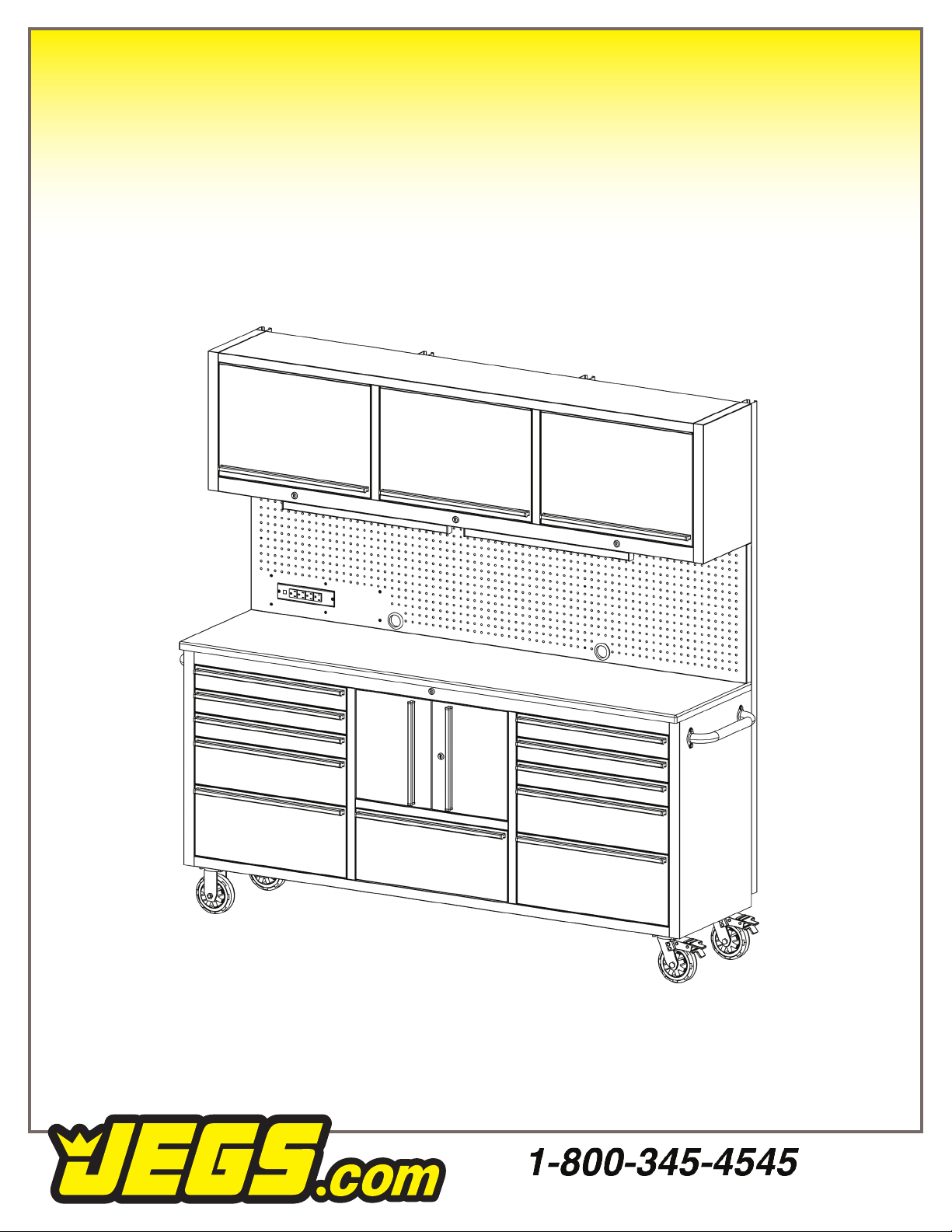
Tool Box with Cabinets
Assembly Guide
555-81445
Stainless Steel | 11-Drawer | 72 in.
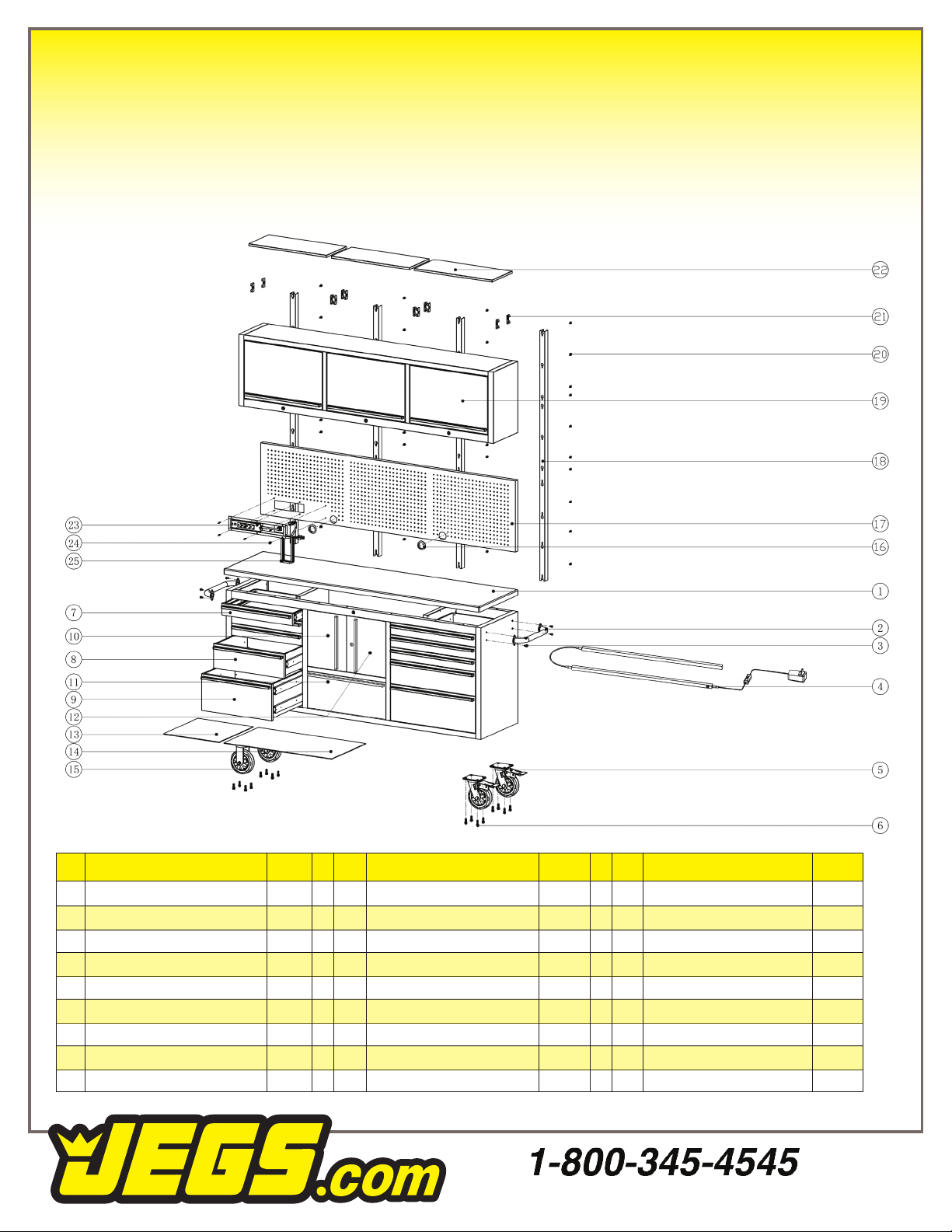
Parts List
# # #
1
2
3
4
5
6
7
8
9
1
1
4
1
2
16
6
2
2
Counter Top
Handle
Bolts (1/4in.)
LED Light Kit
Casters (6 in. Swivel)
Bolts (3/8)
Drawer (Outer Top)
Drawer (Outer Middle)
Drawer (Outer Bottom)
DESCRIPTION DESCRIPTION DESCRIPTION
QTY QTY QTY
10
11
12
13
14
15
16
17
18
Cabinet Door (LH)
Drawer (Center Bottom)
Cabinet Door (RH)
Drawer Liner (Narrow)
Drawer Liner (Wide)
Casters (6 in. Fixed)
Grommet
Pegboard
Upr. Cabinet Support
19
20
21
22
23
24
25
Cabinet Body
Bolts
Wall Mount Hooks
Cabinet Shelves
Power Strip
Bolt (5/32 in.)
Power Cord
1
1
1
5
5
2
2
1
2
1
40
2
3
1
6
1
1

2
Introduction
We would like to take this opportunity to thank you
for purchasing this JEGS 72 in. 11-Drawer Stainless
Steel Tool Box with Cabinets. We welcome any
comments or feedback you might have. If you
have any questions about this product or about
the installation procedure, please feel free to
contact us at 1.800.345.4545.
Fingerprint resistant stainless steel construction
with a 1 1/4in. thick worktop. 100 lb. capacity
drawers with aluminum pull handles and non-
slip liners. Four casters, two xed and two swivel
(which include brakes). Come with a heavy-
duty side handle for comfort and control when
maneuvering. Supplied with locks and key.
IMPORTANT
Please read these instructions carefully.
Note the safe operation requirements,
warnings, and cautions. Use this product for
the purpose for which it is intended. Failure to
do so may result in damage and/or personal
injury, and will void the warranty. Keep these
instructions in a safe place for future use.
Safety
• Locate in a suitable work area.
• Monitor children near the cabinet.
• Do not open more than one drawer at a time.
• Fill from the bottom drawer.
•
If the tool cabinet is lled from the top drawer
down, it will be top heavy and may fall over.
• Do not attempt to lift by the side handles, use
chains, ropes or other lifting devices.
•
Do not use the cabinet as a step or climb
on the drawers.
• Do not alter the product in any way.
•
Do not weld on external lock bars or attach
electrical equipment.
•
Doing so may damage the product and
cause personal injury.
• Keep on a level surface
•
When moving the cabinet DO NOT pull it. Push
the cabinet to prevent injury.
•
Close and lock the drawers before moving the
cabinet. If the drawers come open they could
make the cabinet unstable.
•
Apply brake when the cabinet is in the desired
position.
•
Do not mount on a truck bed or any other
moving object.
• Be aware of sharp edges.

3
Installation
HANDLE (Fig.01)
1. Attach with 1/4in. x 1/2in. bolts, lock washer
and at washers.
CASTERS (Fig.02)
1.
WARNING. Two or more people are required
to lay down or stand up the cabinet. Lock
drawers before turning over.
2.
Carefully lay the cabinet upside down on a soft
mat for protection
3.
Fit the swivel/locking casters on the handle
side of the cabinet using 3/8in. x 1 in. bolts.
Insert the bolts through each caster and into
the bottom of the cabinet. Tighten securely.
4. Repeat for the two rigid casters on the other
side of the cabinet.
Figure 01
Figure 02
Figure 03
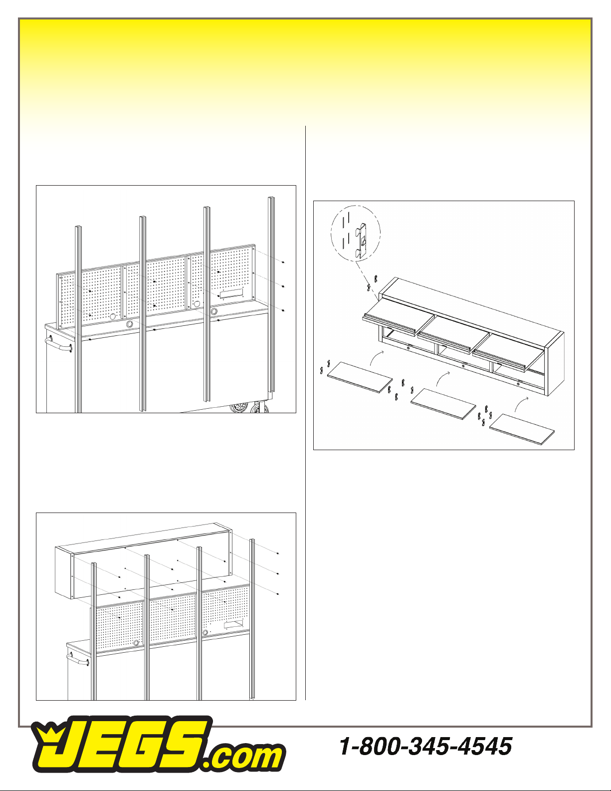
UPPER CABINET RAILS (Fig. 03)
1. With the cabinet in the upright position attach
the four rails to the back using four
1
/
4
in. x
1
/
2
in. bolts per rail.
4
Installation
Figure 04
Figure 05
UPPER CABINET PEGBOARD (Fig. 04)
1.
Attach the pegboard to the rails with three 1/4
in. x 1/2in. bolts per rail.
UPPER CABINET (Fig. 05)
2.
Attach the upper cabinet to the rails with three
1/4in. x 1/2in. bolts per rail.
SHELF ASSEMBLY (Fig. 06)
1.
Insert four hooks, per shelf, inside the upper
cabinet at the desired height. Place the shelf on
the shelf supports. Repeat for the other shelves.
Figure 06
5
Electrical
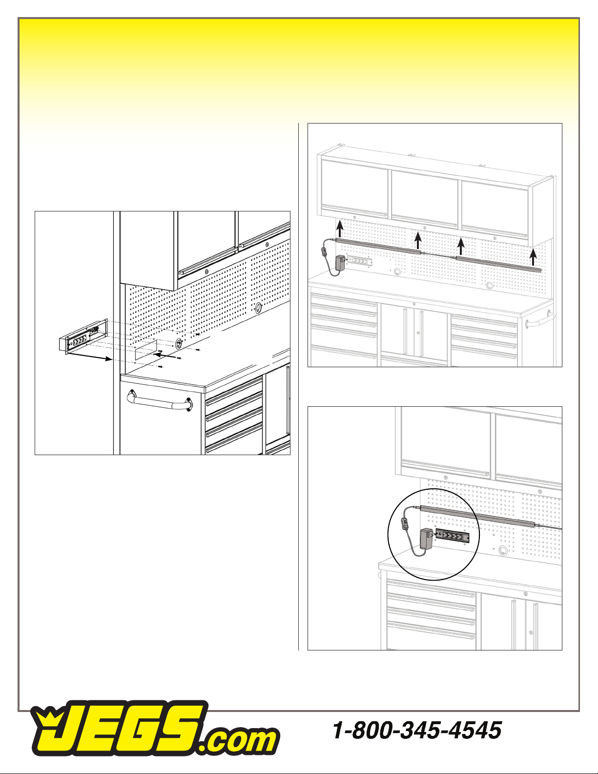
POWER STRIP (Fig.07)
1.
Insert the power strip into the square hole from
the back side of the pegboard. Use 5/32 in.
screws, inserted from the front side to secure
to the pegboard.
Figure 07
Place power strip
on back side of
pegboard
Secure using
screws inserted
from the front
LED LIGHT (Fig. 08 & 09)
1.
The LED light strip is secured to the bottom of the
upper cabinet using magnets. These magnets
are secured in the light’s housing.
2. Plug the light into the cabinet’s power strip.
Figure 08
Plug light into
power strip
Figure 08

6
Operation
DRAWER REMOVAL (Fig.10)
1.
Pull the drawer out so that it is almost fully
extended. Push down on the LEFT hand black
release lever while pulling up on the RIGHT
hand black release lever. While holding the
levers in these positions carefully pull the
drawer outward until it is released from the
drawer slide.
DRAWER REPLACEMENT
1. Extend the drawer slides from the tool chest.
Insert the brackets on each cabinet slide
being careful that they are correctly
positioned. Once inserted, close the drawer to
set the slides in their proper positions.
Figure 10
Electrical
POWER STRIP
This cabinet features a pre-installed power strip with
(4) 5-15 outlets and (2) USB ports, conveniently
located for easy access. The included power
strip has the following ratings:
Maximum Amperage Load.................12A
Maximum Voltage..............................125V
Cycle....................................................60 Hz
Maximum Wattage.........................1500W
USB Output......................5VDC, Max. 2.1A
Plug the provided power cord into the power strip
socket.
110V CIRCUIT REQUIREMENTS
This tool chest is pre-wired to connect to a power
supply circuit that has a veried ground and meets
the following requirements.
Nominal Voltage...........110V, 115V, 120V
Cycle......................................................60Hz
Phase.......................................Single-Phase
Power Supply Circuit....................15 Amps
A power supply circuit includes all electrical
equipment between the breaker box or fuse panel in
the building and the power strip. The power supply
circuit used for this power strip must be sized to
safely handle the full-load current drawn from
the power strip for an extended period of time.
(If this power strip is connected to a circuit
protected by fuses, use a “D” time delay fuse.
GROUNDING & PLUG REQUIREMENTS
This power strip MUST be grounded. In the event
of certain malfunctions or breakdowns, grounding
reduces the risk of electric shock by providing a
path of least resistance for electric current.

7
Maintenance
1. To clean use a soft cloth that will not scratch
the surface.
2.
DO NOT use solvents of any kind they may
damage the surface.
3. Liquid spills should be removed immediately,
use a soft clean cloth to blot the spill gently -
avoid rubbing.
4. Grease the casters with good quality grease
once a year.
5. Lubricate the drawer slides twice a year with
light duty oil.
Anti-Tipping Hardware
It is strongly recommended that you anchor this
cabinet. Toppling furniture can cause serious
injury or death.
An Anti-Tipping kit has been provided with this
cabinet to reduce the risk of injury. (Fig. 11)
This kit securely attaches the cabinet to a wall or
other solid surface using the provided hardware.
It is important to regularly check that the anchors
are securely mounted. The stability of cabinet may
be effected by carpet and uneven ooring.
IMPORTANT
•
Check for wiring or plumbing inside the wall
before drilling.
•
Determine the wall material and use the
appropriate hardware.
Figure 11
8
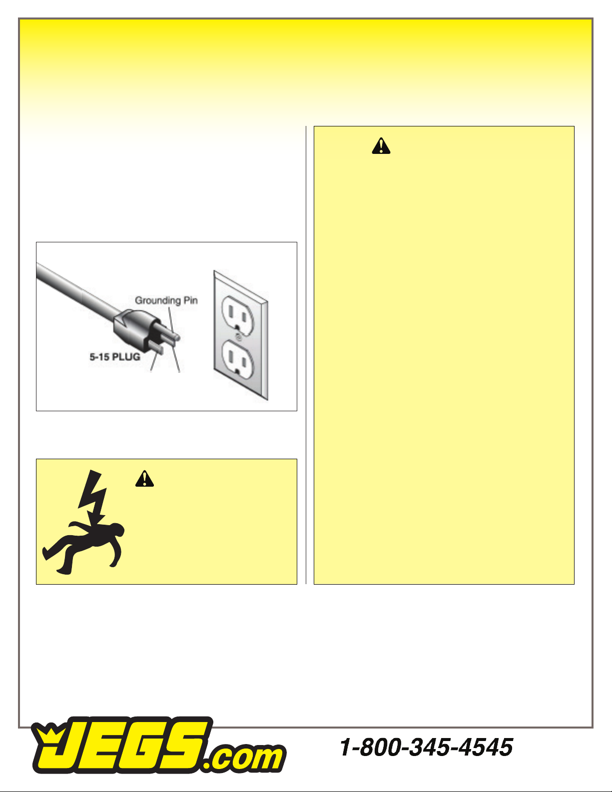
Warning
This power strip is equipped with a power cord
that has an equipment-grounding wire and a
grounding plug. Only insert plug into a matching
receptacle (outlet) that is properly installed and
grounded in accordance with all local codes and
ordinances. DO NOT modify the provided plug!
Grounded 5-15 Receptacle
Neutral Hot
WARNING
•
Do not connect to plug receptacle via
extension cords or in series with other
power strips.
•
Keep electrical connections clear of am mable
materials.
•
Keep electrical connections dry. Do not use
in damp or wet conditions.
• Do not connect devices to power strip that
draw more than listed power strip rating.
Equipment must be used in accordance with
the instructions.
•
Power strips are designed for use with
low-powered loads, such as battery
chargers. Not designed for use with
high-powered loads, such as space heaters
or microwaves.
•
Do not run cord under oor coverings or
where it may be tripped over.
• Not meant for outdoor use.
•
Prevent unauthorized use by children or
untrained users.
WARNING
Electrocution, re, shock,
or equipment damage may
occur if power strip is not
properly grounded and
connected to power supply.
Table of contents
Popular Indoor Furnishing manuals by other brands

modway
modway EEI-4265 Assembly instructions

HAGER Worldwide
HAGER Worldwide Bambach Saddle Seat Classic Small 790099C Assembly and Adjustment Instructions

UpDown Desk
UpDown Desk PRO Series Install manual

Tresanti
Tresanti Joslin 3PK10589 manual

bizzotto
bizzotto KENYA 5732011 Assembly instructions

VITRA
VITRA Alcove Work Assembly instructions

Astonica
Astonica 50105036 Assembly instructions

Noble House Home Furnishings
Noble House Home Furnishings 67035 Assembly instructions

Furniture of America
Furniture of America CM3029T-7PK Assembly instructions

Philips
Philips P-5497-F Specifications

Discovery World Furniture
Discovery World Furniture 2935 instructions

Plaisio
Plaisio Sound Chair 3000 user guide


