manuals.online logo
Brands
  1. Home
  2. •
  3. Brands
  4. •
  5. UpDown Desk
  6. •
  7. Indoor Furnishing
  8. •
  9. UpDown Desk PRO Series Manual

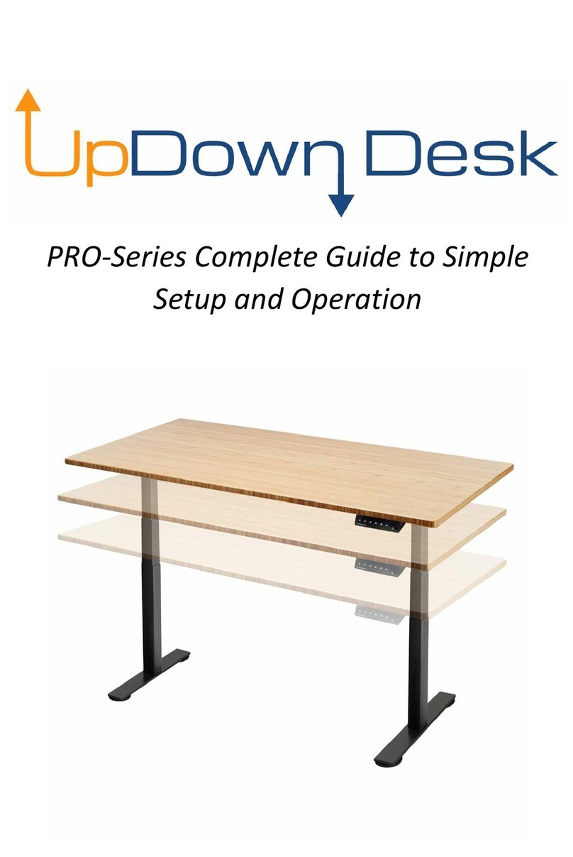
UpDown Desk PRO Series Manual

02
TABLE OF CONTENTS
Introduction
Box Contents
Tool Requirements
Frame Assembly
Desktop Installation
Electrical Components Installation
Control Panel Operation
Troubleshooting
Packaging Recycling and Disposal
03
15
16
04
07
09
12
page
Confirm all the items you received are correct in regards to colour, size, etc.
01
Put the desktop aside.
02
Unpack Frame Box 1 and Box 2. These boxes contain all the parts needed to put your
frame together. We suggest laying all parts out in an open area, preferably close to
where the desk is going to stay.
03
The bag of screws consists of everything that you require for the installation, except for a
Phillips Head screwdriver or power drill with PH2 driver bit if you prefer.
IF YOU HAVE PURCHASED A HARDWOOD DESKTOP - YOU MAY NEED TO USE A POWER DRILL
WHEN FIXING THE CONTROL PANEL, CONTROL BOX AND ACCESSORIES TO THE DESKTOP
04
2 x Legs
2 x Wings
2 x Feet
2 x Sliding Rails
1 x Control Panel
1 x Control Box
1 x Connection Motor Cable
1 x Power Cable
1 x Bag of Screws with Allen Key
a
c
e
b
f
g
h
d
i
M8 x 10mm - 12 pieces in total - large
Allen Key required (supplied) - Used to
attach the legs to the wings and sliding
rails.
M8 x 20mm - 8 pieces in total - large
Allen Key required (supplied) - Used to
attach feet to the legs.
Self Tapping - 16mm - 14 pieces in total
- Phillips head screwdriver required (not
supplied) - Used to attach the control
box and control panel to the desktop,
along with any optional accessories
purchased.
a
c
e
b
fgh
d
i
03
M8 x 10mm
M8 x 20mm
Self Tapping
Phillips Head Screwdriver
required (not supplied)
small Allen Key
M6 x 12mm
either
black OR silver
M6 x 12mm - 8 Pieces in total - small
Allen Key required (supplied with ball on
end) - Used to attach frame to desktop.
These screws will be black if your frame
is black or silver for a white frame.
large Allen Key
Take the 2x Sliding Rails (d), and loosen off every grub screw using the Allen Key.
There is no need to remove the grub screw completely.
Dismantle into individual components.
05
04
M8 x 10mm
You will need the following
parts for this step:
1x Leg (a)
1x Wing (b)
2x outer tubes from the same
side of the Sliding Rail that you
just dismantled in above step
6x M8 x 10mm screws
large Allen Key
06
Inner Rails
Outer Tubes
Aligning the back plate on the leg with the two centralized holes in the wing.
07
Once you have constructed both the leg pieces. Unwrap the desktop and please inspect
both sides to decide which way you want your desktop positioned on your frame.
Place a piece of protective cloth or towel on the ground and then place the desktop
face down, so you can attach the frame to the underisde of the desktop.
08
05
Using the M8 x 10mm screws provided, fasten the Leg (a) to the Wing (b).
Then fasten the two Outer Rails from the Sliding Rails to either side of the Leg.
Make sure the anchor points are facing out.
Repeat this step with the other Leg, Wing and Outer Rails.
Anchor Points
Take one of the constructed leg pieces and position it over one side of the
threaded insert holes of the desktop.
Using M6 x 12 screws and the smaller Allen Key with the ball on the end, loosely tighten
the screws into the insert (not too tight just yet).
09
06
Take the two inner rails that you
removed from the sliding rails
and slide them into the outer
tubes that you fastened to the
desktop.
10
Outer Tube
Inner Rail
Take the other constructed leg
piece and complete the same
as you did above, ensuring
that you slide the inner rails
into the outer tubes of the leg
you are now fixing.
11
M6 x 12mm
07
Line up the threaded insert holes and fasten this leg into the desktop with the remaining
M6 x 12mm screws and smaller Allen Key.
12
PLEASE ENSURE THAT YOU ALIGN THE INNER RAIL IN A CENTRAL POSITION, THIS CAN BE
DETERMINED BY ALIGNING THE MIDPOINT OF THE SLIDING RAIL WITH THE MIDDLE OF THE
DESKTOP.
Mid Point of
Inner Rails
You can now tighten the following screws:
8x grub screws on the Sliding Rails (d) with the larger Allen Key. Please note that if you
have a 180cm desktop, only the 4x inner grub screws will tighten.
8x screws that are fixing the frame to the desktop using the smaller Allen Key.
13
M6 x 12mm
We will now attach the Feet (c) to the ends of the legs.
Using 4 of the M8 x 20mm screws, install the Feet by
loosely tightening the screws.
Once all 4 screws are in, then tighten them off with the
large Allen Key.
Repeat for the other foot.
14
08
Once the frame has been installed you can grab the Control Box (f). The Control Box
features the following plugs:
15
Connection Motor Cable Port
Control Panel Port
Connection Motor Cable Port
Power Cable Port
Connection Motor
Cable Port
Control Panel
Port
Connection Motor
Cable Port
Power Cable
Port
M8 x 20mm
You will now install the Control Box
(f) and Control Panel (e).
Installing the Control Box (f), it is
advised that you plug it into the leg
that is on the same side as you are
wanting the Control Panel (e) to be.
Please ensure that the Control Panel
Port is facing that same Leg.
Once you have that plugged into
the leg, you can go ahead and use
two Self Tapping screws to fix the
Control Box (f) onto the desk, using
either the Phillips head screwdriver
or the power drill.
NOTE: WE RECOMMEND THAT THERE
IS SOME SLACK IN THE CABLE, AS IF IT
IS PULLED TOO TIGHT, THIS MAY
CAUSE DAMAGE OR INCONVENIENCE
WHEN IT COMES TO UNPLUGGING
THE LEG AT ANY STAGE.
16
09
Self Tapping
Once the Control Box (f) has been
fixed you can plug in the other
Connection Motor Cable (g) be-
tween the opposite Leg and Control
Box
17
Choosing which side you want your
Control Panel (e), plug it into the
Control Box (f) and align the Control
Panel with the edge of the desk.
THIS STEP MAY BE EASIER IF YOU
SCREW THE CONTROL PANEL TO THE
POINT YOU CAN STILL SLIDE ENOUGH
SO IT WILL STAY IN PLACE, BUT LOOSE
ENOUGH THAT YOU CAN MOVE IT
BACK AND FORTH - WE RECOMMEND
THIS BECAUSE IT IS EASIER TO ALIGN
THE CONTROL PANEL WITH THE EDGE
OF THE DESK ONCE IT HAS BEEN
18
10
Self Tapping
After completing these two steps, using the 3M cable clips provided, you can gather and
pin back the excess cables to tidy the underside of the desk.
19
AT THIS POINT WE RECOMMEND INSTALLING ANY OF THE FOLLOWING ACCESSORIES
YOU PURCHASED: CABLE TRAY, CASTOR WHEELS, METAL DRAWER.
20
3M cable clip
11
This step may require the assistance of someone else. You need to flip the desk over.
The easiest way to do this is as follows:
21
Once the desk is upright - you can go ahead and finish tightening the screws for the
Control Panel, so that it is aligned with the edge of the desk.
22
You can now take the Power Cable (h) and plug this into the Control Box (f) and then to
the most convenient power point in relation to where you would like your desk to sit. We
advise to not bundle and tie up the excess of the power cord, as this excess cord is
required when raising and lowering your desk.
The most important step of all - ENJOY YOUR PREMIUM UPDOWN DESK.
23
WE RECOMMEND THAT IF YOU DON'T FEEL COMFORTABLE WITH DOING ANY PARTS OF THE
FOLLOWING STEPS THAT YOU GET SOMEONE TO HELP YOU FLIP THE DESK OVER.
Push the desk over so that it stands on the long edge of the desktop that doesn't have
the Control Panel on it.
Grab the opposite sides of the feet and pull back - you want to be careful to do this
slowly as the desk will end up on the edge of the desk and the ends of the metal feet -
we recommend putting something on the ground that you are flipping it on especially if
you have floorboards.
Once in the the following position - walk around to the other side, so you are standing in
the middle of the desktop from here grab the edges and lift up - this step can be broken
into two - the first part being to lift it slightly and sliding something underneath that desk
edge the second part, bending from your knees get your fingers underneath the edge
that is closest to the ground and lift it up, again be mindful that once you get it past a
point that it will start to fall so please take your time in these step.
12
CONTROL PANEL OPERATIONS
Up & Down Display ScreenMemory
The PRO Series desk can be raised manually by pressing the Up/Down buttons or
alternatively by pressing pre-set heights using the M1 – M4 buttons.
To set a height on any given ‘M’ button, use the Up/Down buttons to achieve your desired
position. To store this height, press and hold an M button for 5-6 seconds until you hear a
beep.
The display screen will show your current height. It is pre-set from the factory to show the
lowest height at 64cm, which is measured to the top of a standard 2.5cm thick desktop.
This can be adjusted in the event you install a thicker desktop or castor wheels to your
frame.
The desk has a built in ‘anti-collision’ safety feature whereby any interference or severe
resistance experienced automatically stops the up/down movement of the desk and
rebounds it a small amount. The sensitivity for this can be adjusted.
If you notice the desk has gone to sleep - no numbers are being displayed on the control
panel - you can wake it up with either the arrow buttons or any one of the ‘M” Buttons.
13
ADVANCED FUNCTION SETTINGS
Setting a Min/Max Height - If you have an obstruction in the area that you are looking to
place your desk, such as drawers or CPU underneath, or a window or shelf above the desk.
Min Height - This can be done for any height below 96cms
Max Height - This can be done for any height above 96 cms.
Using the Arrow Buttons - get the desk to the desired height.
Press and hold both Arrow Buttons for 5 seconds until you hear a beep.
This indicates that the desired height has been set.
Remove Max Height
Using the Arrow Buttons - take the desk to the current Max Height.
Press and hold both Arrow Buttons for 5 seconds until you hear a beep.
This indicates that the Max Height has been removed.
Locking the Control Panel - preventing the use of any button function until unlocked
Lock - Press ‘Up’ arrow and ‘M4’ button for 5 seconds.
Screen will display - ‘LOC’
Unlock - Press “Down’ arrow and ‘M4’ button for 5 seconds.
Screen will display height - function is returned.
This control panel has a number of function setting capabilities to customize the display and
operation of the desk:
Furthermore you can access a menu of functions that you can change. To access this list:
Press and hold the ‘M4’ button. You will need to hold it past the first beep and until the
second beep happens (approx 10 seconds)
The screen will display S-1
Using the Arrow Buttons, you can cycle through the following functions:
S-1 - Unit displayed change - Cms / Inches.
S-2 - This is a blank function for future updates.
S-3 - Up Anticollision Sensitivity.
S-4 - Down Anticollision Sensitivity
.
S-5 - Basement Height.
There are a number of other functions that you might see. We recommend not
changing these, as they are factory set.
14
S-1 - Unit Displayed Change - Changes the number display from ‘cm’ to ‘inch’.
At function menu - ‘S-1’ is shown, use the up arrows to get to ‘S-3’
Click ‘M4’
Use the ‘Up’ and ‘Down’ arrows to increase or decrease sensitivity
Note: 1 = Most Insensitive 8 = Most Sensitive
Once adjusted, Click ‘M4’ to return to the height display screen.
S-3 - Up Anticollision sensitivity - This will adjust the sensitivity of the anticollision when the
desk is in ‘Up’ motion.
At function menu - ‘S-1’ is shown, use the up arrows to get to ‘S-4’
Click ‘M4’
Use the ‘Up’ and ‘Down’ arrows to increase or decrease sensitivity
Note: 1 = Most Insensitive 8 = Most Sensitive
Once adjusted, Click ‘M4’ to return to the height display screen.
S-4 - Down Anticollision sensitivity - This will adjust the sensitivity of the anticollision when
the desk is in ‘Down’ motion.
S-2 - Blank Function
When S-1 is showing on screen
Click ‘M4’
From there you can use the arrows to select either of the following
0 - Cm
1 - Inch
Clicking ‘M4’ will return you to the height display screen.
At function menu - ‘S-1’ is shown, use the up arrows to get to ‘S-5’
Click ‘M4’
Use the ‘Up’ and ‘Down’ arrows to change the height that you would like to set.
Once adjusted, Click ‘M4’ to return to the height display screen.
S-5 - Setting Low Display Height - This functionality allows the user to adjust the height
displayed on the screen - this would be utilised when the user has put a thicker desktop onto
the frame than the standard 25mm.
15
TROUBLESHOOTING
For any other troubleshooting issues, please visit the Support section of our website
at updowndesk.com.au.
Error Code
E01, E06, E07
E04
E08
E11, E21, E40, E41
E12, E22, E42, E43
E13-E17, E24-E27
E18, E28
HOT
ASt, RST
E05
Power Fault
Handset Fault
Connection Cable Failure
Controller Fault
Motor Fault
Overloading
Reset Reminder
Anti Collision Alert
Fault Cause Solution
1. Turn power off at power point,
2. Unplug Power Cable from power point.
3. Plug Power Cable back into power point.
4. Turn power back on.
1. Turn power off at power point.
2. Unplug Control Panel from Control Box.
3. Ensure no damage to either ports.
4. Plug Control Panel back into Control Box.
5. Turn power back on
1. Turn power off at power point.
2. Check all connection motor cables.
3. Ensure they are plugged in correctly.
4. Turn power back on.
1. Turn power off at power point.
2. Unplug Control Panel from Control Box.
3. Replug Control Panel into Control Box.
4. Turn power back on.
5. If no changes - Please contact us for a replacement.
1. Turn power off at power point.
2. Unplug Power Cord from Control Box.
3. Replug Power Cord into Control Box.
4. Turn power back on.
5. If no changes - Please contact us for a replacement.
1. Turn power off at power point.
2. Remove items from the top of the desk.We suggest
the easy items to begin with.
3. Turn power back on.
4. If a problem persists please contact us for assistance.
1. Reduce load on desk.
2. Turn power off at the powerpoint.
3. Wait 5 minutes.
4. Turn power back on, lower
Press the down key until the desk reaches the lowest
point and you hear an audible Beep.
1. Turn power off at power point.
2. Ensure there is nothing that is causing the desk to
become uneven.
3. Remove items if the desk is obstructed.
4. Turn power back on.
5. If legs are uneven - hold DOWN arrow until the lowest
height to reset.
Continuous Over Usage (Approx 1
min continuous usage every 10
mins)
Rebound Reminder, normal condition
16
PACKAGING RECYCLING AND DISPOSAL
Your UpDown Desk products come packaged in cardboard boxes and lined with EPE foam
(nontoxic) of various shapes/sizes. The cardboard is 100% recyclable and can be placed (with
foam removed) into your local Council recycle bins or any carboard recycling station. At this
time, there are currently no official recycling stations accepting EPE foam and it is not
accepted in local Council recycle bins.
Based on our own experience and customers suggestions, here are some ideas to help you
upcycle, recycle, reuse, or dispose of the packaging:
Retain the boxes containing frame components in the event you need to move
locations; it’s the best way to transport your frame – unassembled.
The boxes with EPE foam attached make great play equipment for kids; makeshift doll
houses, matchbox car parks etc.
Any cardboard can be recycled without the EPE foam attached in the appropriate
recycling containers.
Local kindergartens and childcare centers will often graciously accept cardboard and
EPE foam for kids’ art and craft projects.
As a last resort, EPE foam can legally be placed into your normal waste bins.

Other manuals for PRO Series

3

Other UpDown Desk Indoor Furnishing manuals

UpDown Desk ECS+ User manual

UpDown Desk

UpDown Desk ECS+ User manual

UpDown Desk PRO Series Manual instruction

UpDown Desk

UpDown Desk PRO Series Manual instruction

UpDown Desk PRO Series User manual

UpDown Desk

UpDown Desk PRO Series User manual

UpDown Desk Metal Drawer User manual

UpDown Desk

UpDown Desk Metal Drawer User manual

UpDown Desk PRO Series Setup guide

UpDown Desk

UpDown Desk PRO Series Setup guide

Popular Indoor Furnishing manuals by other brands

GoodHome adriska 3663602526902 manual

GoodHome

GoodHome adriska 3663602526902 manual

Super Handy GUT154 Operator's manual

Super Handy

Super Handy GUT154 Operator's manual

Furniture of America Lana CM3153ST-2PK Assembly instructions

Furniture of America

Furniture of America Lana CM3153ST-2PK Assembly instructions

Courtyard Creations RTS735G Assembly instructions

Courtyard Creations

Courtyard Creations RTS735G Assembly instructions

HENN Adoleta I715-10 Assembly instructions

HENN

HENN Adoleta I715-10 Assembly instructions

Argos HOME 618/9138 Assembly instructions

Argos

Argos HOME 618/9138 Assembly instructions

BRW KENT EREG 3dw2s Assembly manual

BRW

BRW KENT EREG 3dw2s Assembly manual

Allen + Roth CMC21.32 quick start guide

Allen + Roth

Allen + Roth CMC21.32 quick start guide

Costway OP70517 user manual

Costway

Costway OP70517 user manual

Estate CLSHK16SW Assembly/installation instructions

Estate

Estate CLSHK16SW Assembly/installation instructions

BCP SKY6513 instruction manual

BCP

BCP SKY6513 instruction manual

Sonder CHARLIE FG0801340 Assembly instructions

Sonder

Sonder CHARLIE FG0801340 Assembly instructions

Neutral Posture 1000 Series quick start guide

Neutral Posture

Neutral Posture 1000 Series quick start guide

modway LOVESEAT EEI-3989 quick start guide

modway

modway LOVESEAT EEI-3989 quick start guide

Lomado 0654 Assembly instructions

Lomado

Lomado 0654 Assembly instructions

Costway JV10353DK user manual

Costway

Costway JV10353DK user manual

FourStarGroup 11213619 manual

FourStarGroup

FourStarGroup 11213619 manual

IKEA LINDASEN manual

IKEA

IKEA LINDASEN manual

manuals.online logo
manuals.online logoBrands
  • About & Mission
  • Contact us
  • Privacy Policy
  • Terms and Conditions

Copyright 2025 Manuals.Online. All Rights Reserved.