JENESIS SHS Series User manual

Wherever steam is needed …
JENESIS
SHS SERIES
STEAM GENERATORS
ISIEVİ Makina Sanayi ve Ticaret Limited Şirketi
İkitelli OSB Eskoop Sanayi Sitesi C7-4 Blok No : 479 Başakşehir -İstanbul -TÜRKİYE
Tel : +90 212 595 16 56 ●Fax : +90 212 595 42 39
www.jenesis.com.tr●[email protected]

TABLE OF CONTENTS
PAGE
TABLE OF CONTENTS 2
ASSEMBLY & MAINTENANCE & WARRANTY 3
ASSEMBLY WHICH MUST BE DONE ON-SITE 4
a –Putting the Steam Generator in Place 4
b –Burner Fuel Line Connection 5
c –Smokestack Connection 7
d –Steam Connection 8
e –Condensate Return Connection 10
f –Electric Connections 12
g –Vent Connection 13
h –Blowdown Connection 13
i –Safety Valve Connection 15
J–Water Softening Device Connection (Optional)16
USAGE AND MAINTENANCE INSTRUCTIONS 17
a –Introduction 17
b –Warnings 17
c –Warranty and Service 18
d –General Characteristics 18
e –Operation Conditions 19
f –Fuel Types to Be Used 19
g –Commissioning 19
h –Feed Water Characteristics 20
i –Steam Generator Sections 21
SAFETY & CONTROL22
WARRANTY CONDITIONS 23
START-UP 24
a–Before Start-Up 24
b –Start-Up 29
c –Stopping 34
d –Fault Codes 36
# 1 s. 37 - # 2 s. 38 - # 3 s. 41- # 5 s. 42 - # 6 s. 43- # 7 s. 44 - # 8 s. 45
FAST START-UP 47
DAILY MAINTENANCE 48
WEEKLY MAINTENANCE 50
MONTHLY MAINTENANCE 53
2

•JENESIS PASSPORT
•Type :SHS …../
•Serial Number :……..
•Capacity :……...kW/……….kcal/h
•Steam Production :……….kg/h
•Burner :………...
•Type :…………
•Fuel :…………
•Operation Principle :…………
•Control Panel :ISIEVİ
•Project Number :………….
•Power Needed :……V / …….Hz / …….kW
•Thermostat :…………..
•Thermocouple :…………..
•Feed Pump :…………...
•Type :……………
•Drive Motor :……d/d -…….kW
•Pressure Switches :…………….
•Safety Valve :DN………/ PN………
•Main Steam Valve :DN......../ PN………
•Pressurization Pump :……………
3

Installation, Operating and Maintenance Instructions, Warranty
Certificate, Operating Principle
✓Jenesis Steam Generators are delivered with one operating instructions folder.
✓The folder contains the installation instructions, the general operating and maintenance instructions for
the steam generator, the operating instructions for all parts used on the steam generator (burner, pump,
etc.) and the warranty documents.
4
✓Steam Generators are water pipe steam generators that produce fast steam due to the small volume of
water in them and that do not have a risk of exploding. They are very sensitive to the water used. The
water to be used must be well filtered and free of limescale ions.
✓Steam generator consists of the main body (smoke channel), coil(serpentine)e (pressure hull), burner,
electric control panel, feed water pump, separator, condensate tank and smokestack sections.
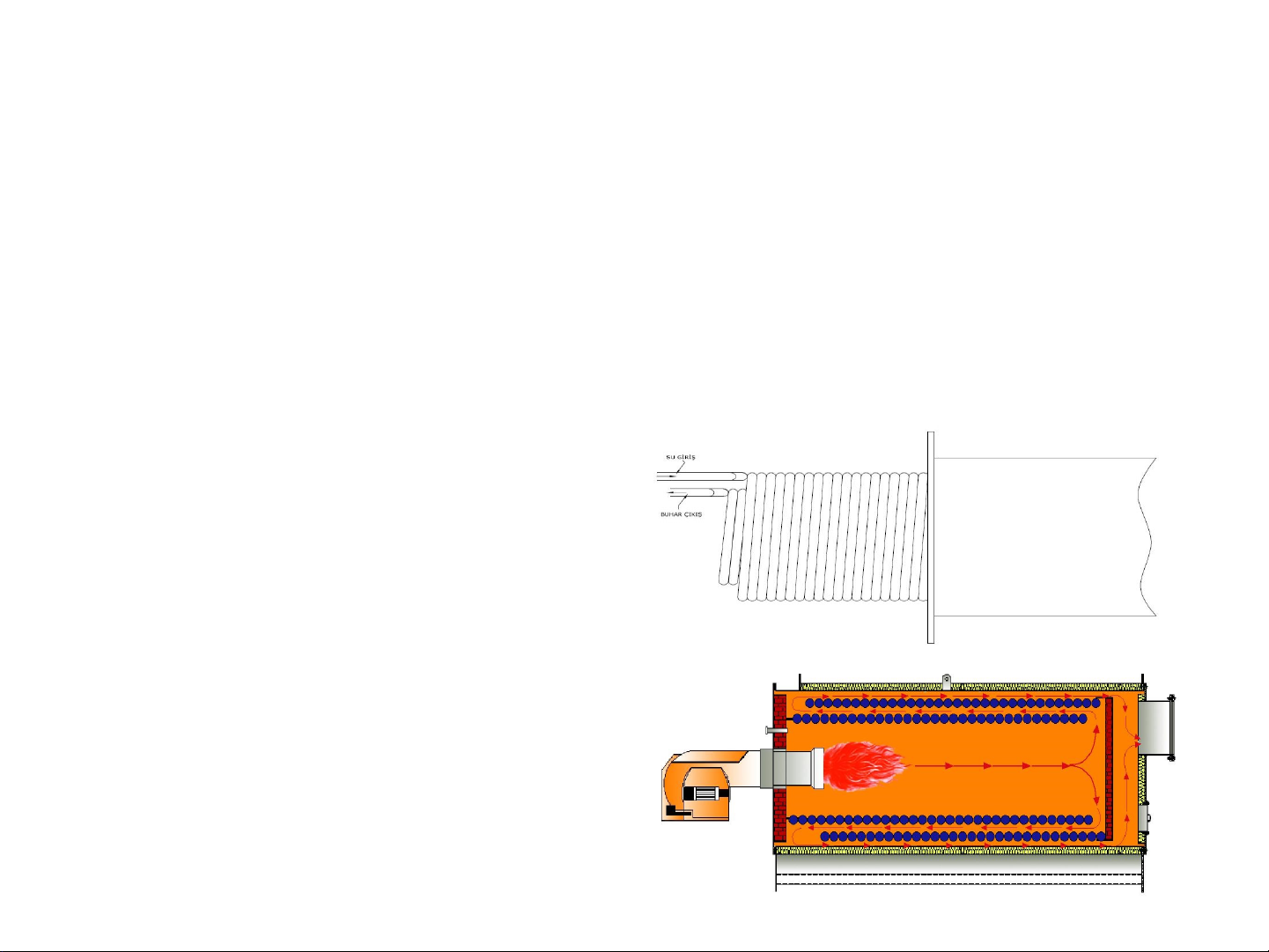
✓As seen in the picture, the “coil(serpentine)”
consists of two intertwined spirals. The inlet and
outlet ports of the spiral are shown on the front
cover.
✓When installing the steam generator, a space equal
to the size of the device must be left on the front
side, in case of removal of the “coil(serpentine)”.
Otherwise, the steam generator “coil(serpentine)”
cannot be removed.
✓The water that is purified by the water softening
device and ready to use in the condensate tank is
pressed in through the coil(serpentine)e inlet port
with feed water pumps. When the burner is
activated, the water in the coil(serpentine)e
evaporates, advances towards the outlet and
reaches the separator. Pressure and temperature
controls are made with the control devices on the
separator and the produced steam is served to the
process by opening the main steam valve.

PLACEMENT & CONNECTIONS
✓WARNING!!! For the commissioning of your steam generator, several assemblies and
connections must be made on site. You must send the photos of the gas opening certificate
and the installations / connections made on site (steam installation, condensate
installation, water installation, electricity installation, blowdown installation and
smokestack connection) to our company.
5
✓The steam generator must be located in
a well-ventilated, frost-free enclosure.
✓The area where the steam generator is
located should be a place with good air
circulation.
✓When positioning the steam generator,
it must be placed in such a way that the
device can be intervened on all four sides.
a–Placement of the Vapor Generator

b - Burner Fuel Line Connection
For Burners Functioning with Liquid Fuel
✓The installation of fuel line system to the indicated parts of the burner.
✓Use preheating tank in the heater and fuel lines on the Fuel-Oil tank.
✓Use a heater on the preheating tank.
✓Use valve and filter on the fuel feed installation.
✓The fuel tank must be located at a level which is proper to the burner.
✓Place the fuel tank at least 5 meters away from the device.
✓Attach the preheating tank vent to the main fuel tank.
✓Use a thermometer on the fuel tank and preheating tank.
✓Check whether or not the is a leak on the fuel line.
6
Fuel-Oil Installation Exemple

For Burners Functioning with Gaseous Fuels
✓The pressure of the gas being fed to the burner must have an appropriate value. (For the natural gas,
this value is 21 millibars or 300 millibars.)
✓A suitable manometer should be used at a place close to the burner, on the gas inflow line of the
burner.
✓In the gas installation, a valve should be used near the burner.
✓Gas installation and connections should be checked and the gas should be opened by the gas
distribution company.
7
Exemple Gas Installation
ATTENTION!!! Unless your
gas line is verified officially
and opened by the gas
distribution company, your
vapor generator cannot be
activated. You must submit
your gas opening
certificate before
activation.

✓In the production of the smokestack, it is necessary to choose the diameter of the smokestack
according to the fuel to be used.
✓Best possible production of the smokestack is necessary for the release of gas waste, for the burner
to burn in the effectively and for your vapor generator to function with the highest efficiency.
8
c–Smokestack Connection
Measurements of Opening of the Smokestack According to Capacities
Model SHS
250
SHS
350
SHS
500
SHS
750
SHS
1000
SHS
1250
SHS
1500
SHS
1700
SHS
2000
SHS
2500
SHS
3000
mm Ø 170 170 280 300 350 350 400 400 400 450 450
✓When connecting the steam generator smokestack outlet to the smokestack, the connection from
the generator to the smokestack must be provided with a 10% slope, which will facilitate the discharge
of the exhaust gas.
ÖRNEK BACA BAGLANTISI
1000 mm
✓When connecting the smokestack flanges, always use a leakproof and
non-flammable gasket.
✓There must be two ½ ”size sleeves on the smokestack. The first one is
required for smokestack gas temperature thermocouple, which provides
value to the smokestack temperature thermostat on the steam
generator electrical control panel, and the other is required to use the
smokestack gas analysis device.
✓The dimensions of a smokestack depend on variables such as smoke
temperature, outside temperature, smokestack load and operating time.
The following formula can be applied for smokestack sizing.

d –Vapor Connection
✓The best quality of the steam produced in the steam generator depends on the quality of the steam
installation in the process.
✓The steam generator steam outlet valve size is given in the table below. The steam installation must
always be one dimension above the steam outlet diameter used. For example, if the main steam valve
of the steam generator is DN50, the steam installation should be DN65.
9
Model
SHS
250
SH
S
350
SHS
500
SHS
750
SHS
1000
SHS
1250
SHS
1500
SHS
1700
SHS
2000
SHS
2500
SHS
3000
DN 32 40 50 65 65 65 80 80 100 100 125
Vapor Connection Measurements According to Capacities
✓In cases where more than one point of steam should be taken from steam generator, steam
distribution collector should be made.
Collecter Application Exemple
✓The steam line from the steam generator to the
collector must be at least one diameter bigger than the
steam generator steam outlet size.
✓The steam distribution collector must be at least two
diameters broader than the steam installation from the
steam generator to the collector.
✓The condensate group should be used for the
condensate formed in the collector.
✓In the steam installations, a slope of 5% should be given
towards the steam generator. This will prevent the water
from the line to advance into the process.

Steam Distribution Connection
Diagram
10
Buhar Dağılım
Kollektörü

✓Attach the condensate return line you are going to use in your process to the indicated entry on the
condensate tank, after checking the necessary installation slopes.
✓Use suitable types and diameters of steam traps on your machine’s condensate outlets.
✓Condensate return diameters should be one diameter less than the diameter of gas installation
entering to the unit.
11
e –Condensate Return Connection
PİSLİK TUTUCU
KONDENSTOP
ÇEKVALF
BY-PASS VANASI
Steam Trap Group Connection Exemple

Condensate Return Connection
Diagram
12

✓Compact electric control panel is used on the steam generator.
✓All the control elements on the steam generator are connected to the electric control panel.
✓The process to be performed on-site on the electrical control panel is to connect the mains
electricity (380V, 50Hz) to the R, S, T and neutral terminals left in the panel.
✓When connecting the mains to the electrical control panel, use cables of appropriate cross-
section. The total power requirement can be found in the electrical connection section of the
metal label on the steam generator.
✓In addition to the R, S, T, and neutral terminals, an external ground terminal is also provided in
the electrical control panel. Electrical control panel and external grounding of the device are
made by our factory. All the user has to do is enter the external grounding at the specified point
on the electrical control panel.
✓The electrical connection you make must be at the required voltage to eliminate possible
disruptions. (380V, 50Hz)
13
f –Electricity Connection
ATTENTION!!! Do not interfere with the
electrical control panel in any way and do not
take external energy for any device operating
with electrical energy. The features of the
parts used in the control panel are determined
and designed considering the power
requirements of the equipment on the steam
generator.
CAUTION!!! Do not take external
grounding as mains neutral. Do not
jump from the neutral terminal to
the external ground terminal. Make
the external grounding as required.

14
g –Vent Connection
✓With the return of the condensate, 10% flash steam is delivered to the condensate tank. If this
flash steam generation is not carried out of the condensate tank, it creates pressure in the tank
and causes deformation.
✓At the same time, the flash steam increases the condensate tank water temperature to very
high values, in which case overheated water will damage your feed pump. Therefore, the outlet
left as a vent on the condensate tank must be carried outside.
✓Depending on the steam generator capacity, a port for the vent is left on the condensate tank.
✓The pipe diameter where the vent installation will be made should not be smaller than the
connection port diameter left on the condensate tank and must be the same diameter or above.
✓Vent connection should be made in such a way that the end is opened to outside environment
without being connected to any installation.
✓Do not use the condensate tank vent outlet for any installation connection.
h –Blowdown Connection
✓Steam generator and condensate tank blowdowns are combined and extended to the bottom
of the tank.
✓The assembly process that is required in place is to take the blowdowns left together to the
outside environment.
✓The blowdown installation must be made above the combined pipe diameter.
✓It should be remembered that for the vents made under pressure, small diameter pipes will not
be sufficient for evacuation.

15
Vent Connection and Blowdown
Connection Diagram

✓Safety valve is located on the vapor generator vapor outlet separator section.
✓When the pressure of the vapor generator passes the maximum operating pressure, safety
valve discharges the surplus vapor and releases it to outside.
✓During the process of connections being done in place, safety valve should be taken to a dead
spot and outside where people cannot be harmed.
✓Safety valve should be installed without making any links to another installation connections.
✓If the present location is favorable, safety valve installation should be made with a slope
towards outside, with a straight pipe.
✓If the safety valve installation cannot be linked to outside with a straight pipe and/or an
attachment material similar to elbow is being used; relief valve application must be used, as the
place in which these components are situated will be filled with water.
16
i –Safety Valve Connection
BUHAR ÇIKIŞ
SEPERATÖRÜ
EMNİYET
VENTİLİ
EMNİYET VENTİLİ TAHLİYE BORUSU

17
j –Water Softening Device Connection
✓At the entrance of the water softener, there is a sediment filter, valve and manometer which
are left by the factory.
✓The on-site connection is to connect the mains water to the valve on the inlet of the water
softener.
✓A pipe fitting must be used when connecting the mains water to the device. A valve should be
installed at the outlet of the device to shut off the water if necessary and a sampling tap to take
samples from the outlet of the device.
✓Following the connection of the mains water, the water softener must be fed with water and
the pressure fed from the pressure gauge left on the softener should be observed.
✓Water softening devices require water and water pressure for regeneration. Inlet water
pressure must be min. 3 and max. 6 bars.
✓If the mains water is not at the desired pressure, a storage tank and a booster must be
positioned to pressurize the water.
✓If the water used is supplied from a source other than mains water (such as well water), the
water must be subjected to good filtration.
✓A 220 V socket must be located near the water softener for the electrical supply.
✓Water softening devices use a 12 V adapter for power supply. (Delivered with device.)
✓Regeneration process in water softening devices is set at 02:00 at night. For this reason, the
220 V socket positioned for the water softener adapter must be set to provide electricity for 24
hours.
✓During the regeneration, the water softener discharges the waste water from the outlet at the
rear of the device. This outlet should be connected to a drain.

18
USAGE AND MAINTENANCE INSTRUCTIONS
a–Introduction
✓Thank you for choosing ISIEVİ.
✓In this brochure, the assembly, usage and maintenance instructions of JENESIS SHS Type Vapor Generators are
found, which are produced by ISIEVİ.
✓If you wish to use your device with high efficiency, comfortably and without any problems, observe the directives in
this brochure carefully. To start up, maintain and fix the device, please contact the technical staff. After the assembly
and start-up of your device, Technical Staff will inform you about the usage of the device.
b–Warnings
✓The steam generator must be located in a well-ventilated, frost-free enclosure.
✓The generator is designed for steam production only. The system operating temperature and pressure must
correspond to the label values. The Steam Generator may only be used with liquid or gas fuel systems specified in this
manual.
✓In order to use the steam generator efficiently, burners certified according to EN 676 (Gas Fired) according to the
Gas Burners Directive should be used.
✓Feed water characteristics to be used in steam generators must meet the specified criteria. The use of soft, clean
and non-corrosive water is very important for economic operation and system life.
✓There should be no flammable gas and liquid in the area where the steam generators are located.
✓Ignition is automatic in liquid or gas burners. There are many additional safety precautions on the system..
✓Do not touch the flame sight glass, smokestack and smoke box sections and surroundings with bare hands. These
areas are hot and can cause injuries.
✓It is recommended to install an emergency stop switch to cut off the main energy outside the boiler room.
✓The first controls and commissioning of a newly installed system are carried out by ISIEVİ MAKİNA authorized
technical services. In case of a change in fuel in the future, please contact the Technical Service of the device.
✓The manufacturer is not liable for failures arising from revisions made without the knowledge of the manufacturer
and in such cases the steam generator shall be excluded from the warranty.

ATTENTION!!! In order for your Steam Generator to be commissioned, the installation and connection
procedures required on-site must be carried out completely. The pictures of your gas opening certificate and
the installations and connections you have made (steam installation, condensate installation, water
installation, electrical installation, blowdown installation and smokestack connection) should be sent to our
company.
19
c–Warranty and Service
✓In order for the warranty to be valid, the ‘Warranty Certificate’ must be approved by the manufacturer from
which you purchased the device. Improper installation, maintenance or usage is not covered by the warranty. The
failures caused by the coating of the heat transfer parts of the steam generator with lime and / or similar
substances or caused by corrosion and all other water-related failures are not covered by the warranty.
d–General Characteristics
✓It is a slant type device with water pipes. Generates steam in a very short time. It has a high efficiency, a long life and it
is fully automatic. It consists of a spiral curved, intertwined double-row coil (serpentine). The water volume is extremely
small. According to TS 2736, Annex 2. Article 2.11, there is no harm in placing it in the building without a separate boiler
room. It has a highly advanced security equipment. The body of the steam generator is insulated by covering the static
powder coated hair on rock wool.
✓With JENESIS Steam Generators, high efficiency monoblock burners with widespread service networks which have CE
and TSE are preferred. SPECK triplex piston pumps are used as feed water pumps.
✓Safety valve ensures safe operation of the system by releasing steam at possible pressure increases.
✓Safety switch allows the system (burner and pump) to stop when the set pressure is reached in case of failure of the
operating switch.
✓In addition to displaying the steam temperature from the digital display during operation, the steam thermostat stops
the system if the generator exceeds the maximum steam temperature set in case of possible dehydration.
✓Fe - Const temperature sensing element is used to measure the steam temperature accurately.
✓The smokestack gas thermostat will display the flue gas temperature from the digital display during operation, and the
system will stop and operate if the value exceeds the maximum smokestack gas temperature allowed by the municipality
and other public institutions.
✓Fe - Const elements and special cable are used to measure the smokestack gas temperature as well as the steam
temperature.

e–Operating Conditions
✓Type SHS Vapor Generators are designed to generate vapor.
✓Water should be supplied with appropriate hardness through the feed water inlet.
✓The feed water inlet hardness value used should be 0˚Fr.
✓Daily, weekly and monthly controls and maintenance should be carried out according to the
instructions for use.
20
f–Fuel Types to Be Used
✓SHS type Steam Generators are designed according to the usage of Diesel, Biodiesel, Fuel-Oil
fuel types in liquid fuels and Natural Gas (LNG, CNG) and LPG fuel options in gas fuels. Do not,
under any circumstances, change the settings of the fuel units of your device other than these
types of fuel.
g - Commissioning - Controls to be done before commissioning
✓Perform the hardness analysis of the water to be used, it should be 00 (zero) F.
✓Check the fuel line for fuel.
✓Check the condensate tank for water.
✓Check the supply system for closed valves. (Fuel supply valve, condensate tank filling
installation, pump supply installation)
✓Check the feed pump connections (oil, water) for leaks.
✓Check that the oil level is within the proper range and that water is not mixed into the oil from
the oil pump dipstick.
✓Change the pump oil every 3 months. Type of oil to be used (SAE 90 GL 4).
This manual suits for next models
11
Table of contents