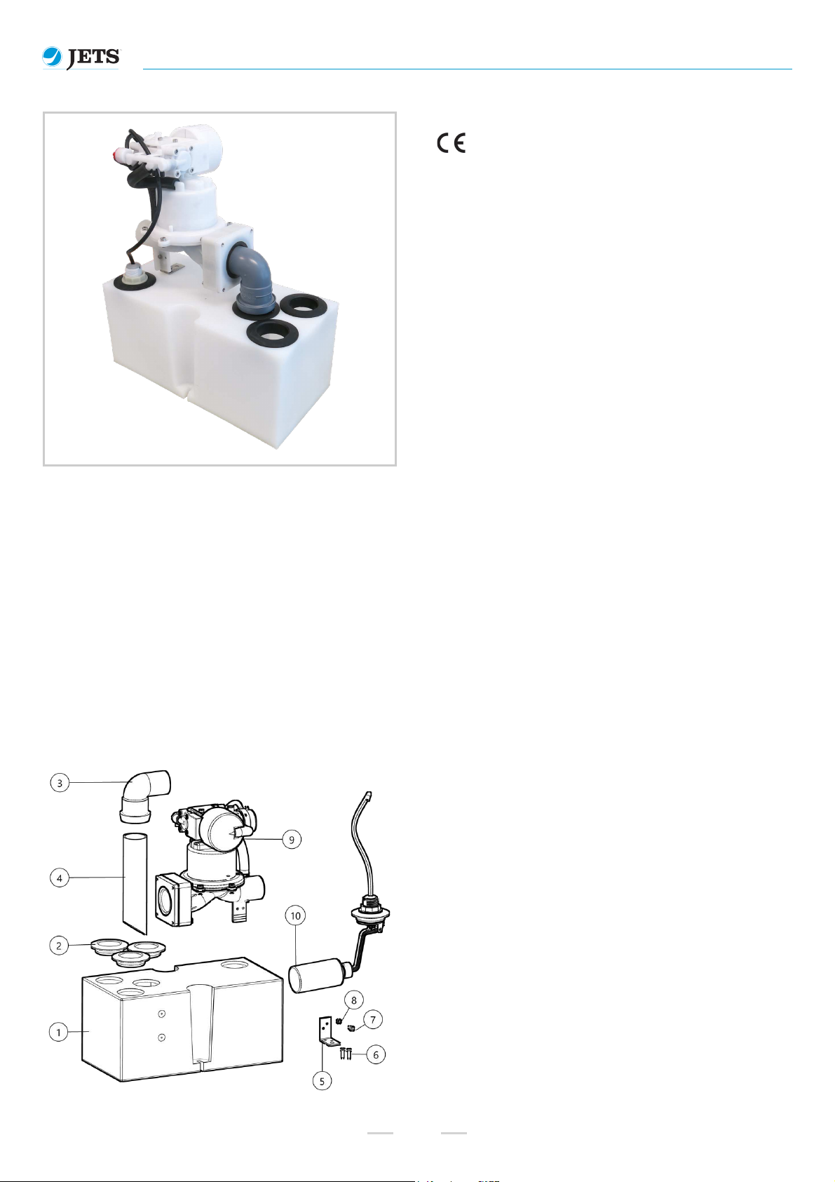
Grey Water Interface Unit 12L Tel. +47 70 03 91 00
www.jetsgroup.com
Product No. GWT800PL Doc. Rev.: 2 (2019-06-17)
4
Important Health and Safety Information
Installation, operation and maintenance must be carried out in strict accordance with this guide and with all applicable regulations. For your own
protection and the protection of others, it is necessary to familiarize yourself with, and always follow, the contained safety and environmental
precautions for our products.
This manual is an integral part of the product/delivery. Always keep it in a safe place for future reference. It is entirely the owner’s responsibility to
ensure that all safety and environmental measures, in accordance with local, state and federal laws are followed. Jets Vacuum AS assumes no
responsibility for equipment damage, personal injury or death and/or delays that result from a lack of respect for the instructions for installation
and/or use as stated in this documentation. Disregarding these instructions may invalidate all warranties.
Safety information references are in accordance with Jets Vacuum AS documentation system. If you do not understand the warnings, stop work
immediately and contact Jets Vacuum AS (citing the safety reference number) for further clarification.
For further information about the included warnings or any other safety concerns please contact Jets Vacuum AS.
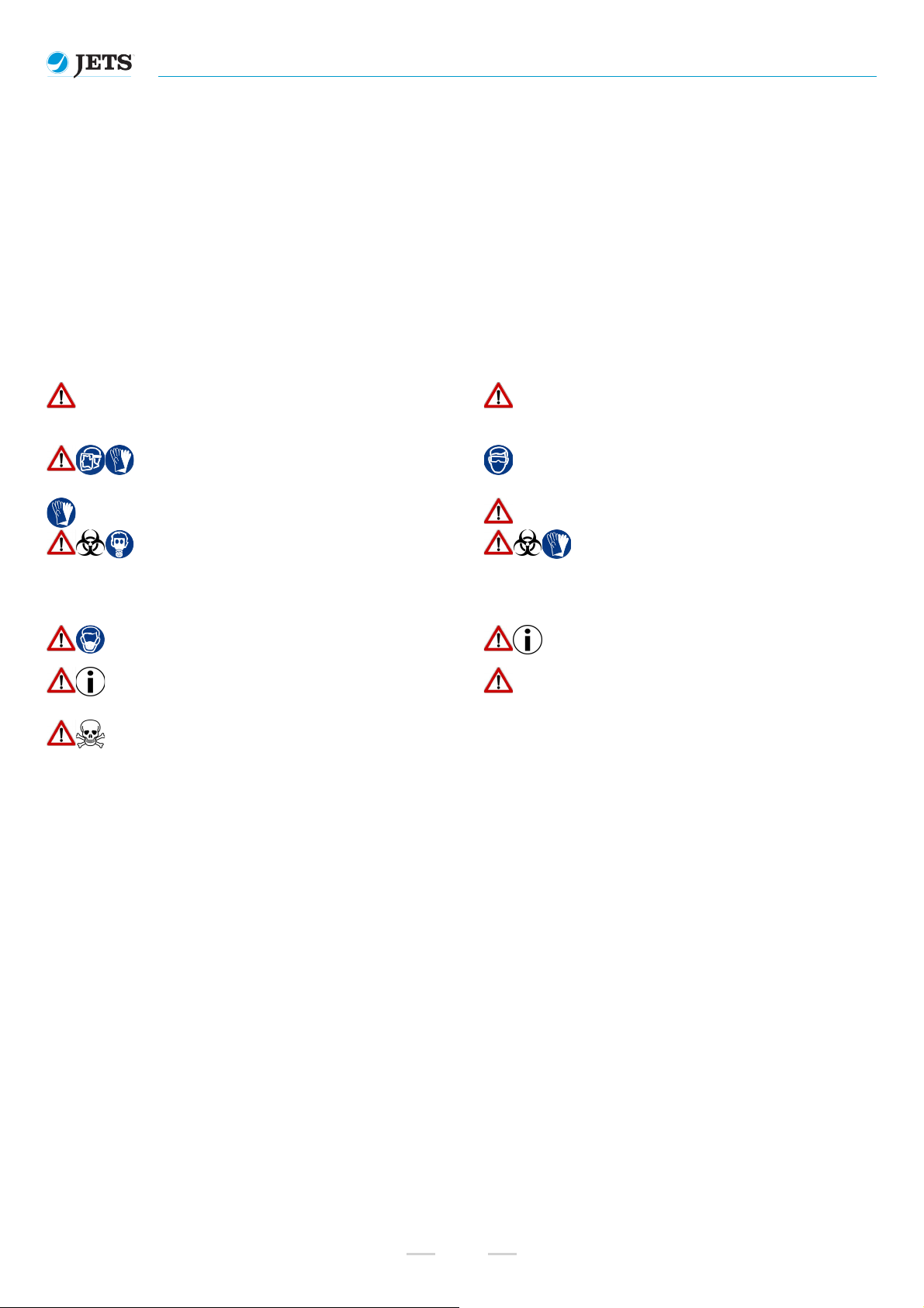
Important Health and Safety Warnings
1.1 Warning
Jets Vacuum AS recommend qualified person(s) in accordance with all applicable
codes and standards to carry out all installation work, electrical wiring, plumbing and
operate this product. Equipment damage, injury to personnel or death could result
from improper installation/use.
1.2 Warning
Be thoroughly familiar with the controls and the proper use of the equipment prior
to installing, starting or using the equipment. Know the equipment application,
limitations and potential hazards.
1.4 Caution
Safety equipment (PPE) necessary for the prevention of accidents at the
installation and operating site must be provided in accordance with local
regulations.
1.5 Personal Protective Equipment - Goggles
Wear safety glasses with side shields at all times when working with equipment.
1.9 Personal Protective Equipment - Gloves
Wear suitable protective gloves at all times when working with equipment.
2.6 Notice
Place the equipment in an area that is easily accessible for maintenance.
9.1 Danger
Gas Hazards: Putrefied organic matter will produce disagreeable odors and an
oxygen deficient atmosphere. During service of tanks, sufficient exterior air
must ventilate the tank to counteract the oxygen deficient environment prior to
service being carried out. Under no circumstances should a person service the
tank without a second person standing by that can render aid if needed. If
extended periods of time are required for tank inspections/repairs, appropriate
respiratory equipment (PPE) should be utilized.
9.2 Danger
Disease Hazards: Effluent is a common mode of transmission for parasitic
organisms. Some of these may be pathogenic, meaning that they may
have the capability of causing serious communicable disease. Good
personal hygiene, use of disinfectant soap and avoidance of hand to
mouth transfer are necessary for all working in contact with the
equipment. Skin abrasions, punctures or wounds of any other nature
require immediate and proper medical attention.
9.8 Warning
Avoid breathing in dust from grey water.
12.5 Notice
Use this equipment only in the manner intended by Jets Vacuum AS. If you have
questions after reading these instructions contact Jets Vacuum AS directly.
12.7 Notice
Additional and replacement parts should only be obtained from the manufacturer or
distributor.
2.13 Caution
Installation, service and maintenance are to be carried out with due care. Shock,
innapropriate handling, incorrect use of tools and general mishandling of the
product may result in damage to components.
10.5 Notice
Chemical detergents, when used excessively, may result in foaming in discharge from
the Vacuumarator™ pump.
Delivery, Receipt of Goods and Transportation
Goods to be protected against shock and damage. Suitable adequately dimensioned transporting equipment is to be used. Note that the
equipment may contain components that are easily damaged as a result of inappropriate handling. Jets Vacuum AS is not responsible for or liable
for delivery delays resulting from occurrences outside of Jets Vacuum AS' immediate control. On receipt of goods, check for visual damage. Any
damage detected after dispatch should be reported immediately to Jets Vacuum AS. Damages and/or discrepancies must be reported in writing no
later than eight (8) days after receipt of goods. Commissioning must be postponed until the equipment has been inspected. Do not dispose of
damaged items. Your direct supplier will advise you of the procedure to follow.
Storage
Unless otherwise specified, goods are to be stored in a dry environment between -30°C and +40°C prior to installation. The storage location must
be dust free, low humidity (≤95%) and be free from moisture. Keep clear of foreign objects.
Installation to End Use
Site to be a dry environment between +0°C and +60°C. Use in environments below 0°C requires use of antifreeze in liquids. The site location is to
be low vibration Vrms ˂0.2 mm/s) with vibration resistance to acceleration up to 0.7g. The site is to be dust free and protected from grinding and
welding. Goods are to be stored as per the instructions for delivery, storage and transport. A visual inspection is to carried out on receipt of goods
as well as at the time of installation to ensure that storage and transport conditions after receipt have not compromised the quality of the product/s.