JFR Medical Cube 30 ATV User manual

JFRMedicalInstrumentsGmbH
Ostuferhafen 15, 24149 Kiel, Germany
T: 0431 - 7298 740-0, F: 0431 - 7298 740-19
Customer Service:
Version 04/2017 - User Manual, Cube 30 ATV, English
Software Version: 1.X.X
Cube 30 ATV
Ventilator
UserManual

TABLEOFCONTENTS
1. INTRODUCTION........................................1
1.1 Intended use . . . . . . . . . . . . . . . . . . . . . . . . . . . . . . . . . . . . 1
1.2 Contraindication . . . . . . . . . . . . . . . . . . . . . . . . . . . . . . . . . 1
1.3 Side effects . . . . . . . . . . . . . . . . . . . . . . . . . . . . . . . . . . . . . 2
2. OVERVIEWOFTHEDEVICE.............................3
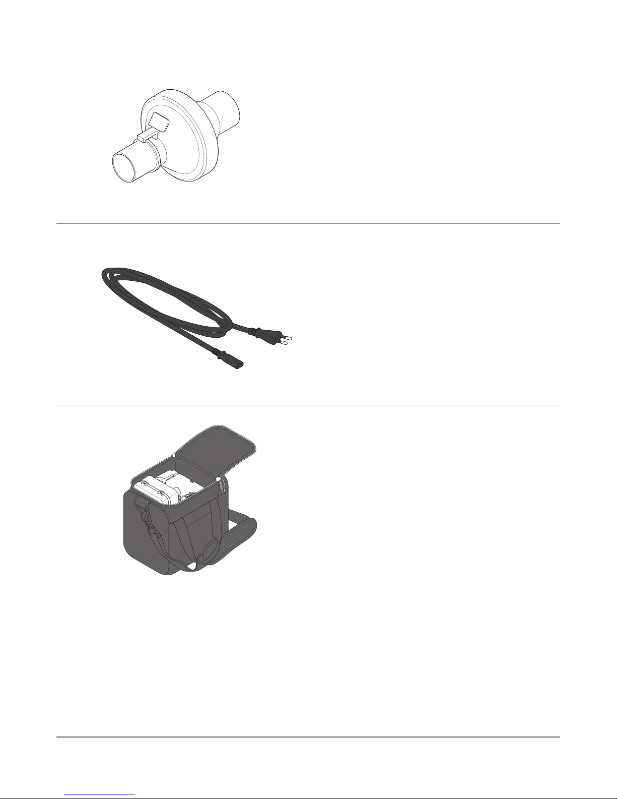
2.1 Accessories . . . . . . . . . . . . . . . . . . . . . . . . . . . . . . . . . . . . . 5
2.2 Explanation of symbols . . . . . . . . . . . . . . . . . . . . . . . . . . . . 8
3. PUTTINGTHEDEVICEINTOSERVICE...................10
3.1 Setting up the device . . . . . . . . . . . . . . . . . . . . . . . . . . . . . 10
3.2 Connecting the device . . . . . . . . . . . . . . . . . . . . . . . . . . . . 10
3.3 Fitting the respiratory mask . . . . . . . . . . . . . . . . . . . . . . . . . 14
3.4 Connecting bacterial filter . . . . . . . . . . . . . . . . . . . . . . . . . . 15
4. USINGTHEDEVICEDAILY..............................16
4.1 Starting therapy . . . . . . . . . . . . . . . . . . . . . . . . . . . . . . . . . . 16
4.2 Setting the respiratory humidifier . . . . . . . . . . . . . . . . . . . . 16
4.3 Switching therapy sets . . . . . . . . . . . . . . . . . . . . . . . . . . . . 17
4.4 Handling alarms . . . . . . . . . . . . . . . . . . . . . . . . . . . . . . . . . 17
4.5 Stopping therapy . . . . . . . . . . . . . . . . . . . . . . . . . . . . . . . . 20
4.6 Switching off the device . . . . . . . . . . . . . . . . . . . . . . . . . . . 20
4.7 Travelling with device . . . . . . . . . . . . . . . . . . . . . . . . . . . . . 20
5. FUNCTIONALDESCRIPTION ............................22
5.1 General function of the device . . . . . . . . . . . . . . . . . . . . . . 22
5.2 Therapy modes . . . . . . . . . . . . . . . . . . . . . . . . . . . . . . . . . . 22
5.3 Additional therapy functions . . . . . . . . . . . . . . . . . . . . . . . . 24
5.4 Alarms . . . . . . . . . . . . . . . . . . . . . . . . . . . . . . . . . . . . . . . . . 24
6. SETTINGTHEDEVICE...................................26
6.1 Control panel . . . . . . . . . . . . . . . . . . . . . . . . . . . . . . . . . . . . 26
6.2 Standby screen . . . . . . . . . . . . . . . . . . . . . . . . . . . . . . . . . . 27
6.3 Menu . . . . . . . . . . . . . . . . . . . . . . . . . . . . . . . . . . . . . . . . . . 30
6.4 Viewing the data logs . . . . . . . . . . . . . . . . . . . . . . . . . . . . . 33
6.5 Data management . . . . . . . . . . . . . . . . . . . . . . . . . . . . . . . 34
6.6 Function test . . . . . . . . . . . . . . . . . . . . . . . . . . . . . . . . . . . . 35

6.7 Testing the alarms . . . . . . . . . . . . . . . . . . . . . . . . . . . . . . . 35
7. OPERATINGMALFUNCTIONS...........................38
7.1 Alarms . . . . . . . . . . . . . . . . . . . . . . . . . . . . . . . . . . . . . . . . . 38
7.2 Handling errors . . . . . . . . . . . . . . . . . . . . . . . . . . . . . . . . . . 43
8. CLEANINGANDMAINTAININGTHEDEVICE.............47
8.1 Intervals . . . . . . . . . . . . . . . . . . . . . . . . . . . . . . . . . . . . . . . 47
8.2 Cleaning . . . . . . . . . . . . . . . . . . . . . . . . . . . . . . . . . . . . . . . 48
8.3 Maintenance . . . . . . . . . . . . . . . . . . . . . . . . . . . . . . . . . . . . 51
8.4 Disinfection . . . . . . . . . . . . . . . . . . . . . . . . . . . . . . . . . . . . . 52
8.5 Disposing of . . . . . . . . . . . . . . . . . . . . . . . . . . . . . . . . . . . . 53
9. SCOPEOFDELIVERY....................................54
9.1 Standard scope of delivery Cube 30 ATV . . . . . . . . . . . . . 54
9.2 Accessories/spare parts . . . . . . . . . . . . . . . . . . . . . . . . . . . 54
10. TECHNICALDATA......................................55
10.1 Technical data . . . . . . . . . . . . . . . . . . . . . . . . . . . . . . . . . . . 55
10.2 Display values therapy status range . . . . . . . . . . . . . . . . . . 58
10.3 Setting ranges and accuracy of the therapy settings . . . . . 59
10.4 Setting ranges and accuracy of the alarm parameters . . . . 61
10.5 Pneumatic circuit diagram . . . . . . . . . . . . . . . . . . . . . . . . . . 61
10.6 Protective Distance . . . . . . . . . . . . . . . . . . . . . . . . . . . . . . . 62
11. SAFETYINFORMATION/WARNINGS....................63
11.1 Operating the device . . . . . . . . . . . . . . . . . . . . . . . . . . . . . . 63
11.2 Transport/maintenance . . . . . . . . . . . . . . . . . . . . . . . . . . . . 64
12. INDEX..................................................66

Introduction 1
1. INTRODUCTION
Please read the complete user manual carefully before using the device.
This manual is aimed at users without clinical background. The manual is
shortened compared to the clinical manual.
Note If questions on turning on, operating or maintaining the device remain,
please contact your service provider.
1.1 Intendeduse
This Cube 30 ATV is a device for non-invasive, non-life supporting respiration
of spontaneously breathing patients who have a body weight of at least 13 kg
and suffer from respiratory insufficiency.
These clinical pictures include:
• Chronic obstructive pulmonary disorder (COPD)
• Neurological, muscular and neuromuscular complaints, such as paresis of
the diaphragm
• Restrictive ventilation disorders, e.g. scoliosis, thorax deformities
• Central respiratory regulatory disorders
• Obstructive sleep apnoea (OSA).
The device is suitable for use at home and in clinics (hospitals, sleep labora-
tories etc.).
1.2 Contraindication
The Cube 30 ATV is not a life-supporting system and may therefore not be
used by patients that are only able to tolerate short interruptions in ventilation.
The use of the device could also be contraindicated among patients who suffer
from the following conditions:
• Pneumothorax or pneumomediastinum
• Risk of aspirating stomach contents

2Introduction
• Hypotension, particularly combined with intravascular volume depletion
• Fluid discharge, short-term cranial operation or trauma
• Acute sinus or middle-ear inflammation
•Dehydration
• Severe bullous pulmonary inflammation.
1.3 Sideeffects
Please contact your doctor immediately if you experienced severe headache,
unusual chest pain or shortness of breath.
The following side effects can arise with non-invasive ventilation with this de-
vice:
• Irritation of the eye/conjunctiva inflammation
• Ear and nasal cavity symptoms
• Nose bleeds
• Skin irritation or damage
• Dryness of the mouth, throat or nose
• Bloated stomach or feeling of fullness.

Overview of the device 3
2. OVERVIEWOFTHEDEVICE
You will find the scope of supply included as standard in section 9.1 on
Page 54.
1. Control panel with display
2. Start/stop button
3. Safety clip (mains cable)
4. Mains socket
5. USB A connection
6. Micro USB connection
7. Air outlet (if used without respira-
tory humidifier) and silicone cover
for air outlet
8. Loudspeaker
9. Air outlet (if used with respiratory
humidifier)
10. Air inlet and fine or coarse filter
1
2
3 4 5 6 7 8
910

4Overview of the device
11. Connection socket for respiratory
humidifier
12. Type plate
13. Air outlet (if used with respiratory
humidifier)
14. LED for respiratory humidifier
15. Audio-pause key
16. Navigation buttons
17. OK key
18. Ramp key
19. Display
11 1312
19
18
17
14
15
16

Overview of the device 5
2.1 Accessories
2.1.1 Optionalrespiratoryhumidifier
(notyetavailableatthemoment)
20. Lock clamp
21. Air inlet of the respiratory humidifier
22. Air outlet
23. Connection socket for respiratory
device
24. Release button
25. Heating plate
26. Cover for water chamber
27. Opening lever to the water cham-
ber
28. Heat transfer plate (bottom)
29. Level indicator to the water cham-
ber
30. Water bowl to the water chamber
31. Unlocking handle to the water
chamber
21 22 2423
25
20
2826 27
31 29 30 29

6Overview of the device
32. Type plate to the respiratory humid-
ifier
33. Storage compartment for the sili-
cone cover of the power connector
(if respiratory humidifier is used)
2.1.2 Furtheraccessories
Tube system
in accordance with ISO 5367
Respiratory mask
(diagram, not included in the scope
of supply)
32
33

Overview of the device 7
Bacterial filter
(diagram, not included in the scope
of supply)
Mains cable (EU type)
Transport bag

8Overview of the device
2.2 Explanationofsymbols
Symbolsontypeplate
Symbol Meaning
Manufacturer
Date of manufacture
Serial number
Model number
Alternating current
Protection rating II
Type BF application part
IP21
Protection from: IP21 + spillage
Protection against the ingress of solid foreign bodies ≥12.5 mm
diameter and larger, and against vertically falling water droplets plus
spillage
CE declaration of conformity
The device cannot be disposed of in domestic waste. You can find
information about the proper disposal of the device on Page 62.

Overview of the device 9
Symbolsonthedevice
Symbolsintheclinicalmanual
Symbol Meaning
Follow user instructions
Alternating current
USB connections
Loudspeaker
Symbol Meaning
WARNING
This symbol designates an extraordinarily dangerous situation. Fail-
ure to follow this information can result in serious injuries and even
death.
CAUTION
This symbol designates a dangerous situation. Failure to follow this
information can result in slight or moderate injuries.
Note
This symbol designates information, indications and tips on how to
handle the device without any problems.

10 Putting the device into service
3. PUTTINGTHEDEVICEINTOSERVICE
3.1 Settingupthedevice
• Ensure that the device is put into service by following the instructions
below.
• Place the device a minimum distance of 5 cm from the wall.
• Place the device on a level, dust-free surface, such as a bedside table or
on the floor next to the bed.
• Do not place the device on a soft surface, such as a bed or a couch.
• Place the device in such a way that the mains plug can be unplugged at
any time without problems.
• Pay attention that the therapy tube cannot strangulate the patient.
3.2 Connectingthedevice
The device can be used with or without respiratory humidifier. (The respiratory
humidifier is not yet available at the moment.)
Withoutrespiratoryhumidifier
1. The openings to the air outlet and the connection socket for the respira-
tory humidifier can be found underneath the device. Check that the open-
ings are sealed with the silicone covers provided.
Warning Take care when setting up the device that the air
inlet on the back of the device is not blocked by cur-
tains, bedding etc.

Putting the device into service 11
2. Connect the power mains cable to the device. Secure the power cable to
the device with the help of the safety clip. Insert the other end of the
mains cable into a socket.
3. Connect the respiratory tube on the air outlet on the back of the device.
4. Connect the other end of the respiratory tube to the mask.

12 Putting the device into service
Withrespiratoryhumidifier
(notyetavailable)
1. Check that the opening for the air outlet on the back of the device is
closed with the silicone cover.
2. Ensure that the silicone cover for the respiratory humidifier's connection
socket under the device has been removed.
3. There is a storage recess for the silicone cover of the connection under-
neath the respiratory humidifier. Insert the silicone cover into this storage
recess to avoid this getting lost by accident.
Underside of
respiratory humidifier

Putting the device into service 13
4. Connect the respiratory humidifier to the device. To do this, place the
device on the respiratory humidifier so that it is connected on the front.
Ensure that the lock clamp of the respiratory humidifier hooks into the
corresponding lugs of the device. Press the back of the device down.
5. Connect the power mains cable to the device. Secure the power cable to
the device with the help of the safety clip. Insert the other end of the
mains cable into a socket.

14 Putting the device into service
6. Connect the respiratory tube to the air outlet on the respiratory humidi-
fier.
7. Connect the other end of the respiratory tube to the mask.
3.3 Fittingtherespiratorymask
Note The device requires a respiratory mask with integrated air outlet. Other-
wise, CO2may be reinhaled.
The device is suitable for use with nasal, oral-nasal, pillow and full-face masks.
Please follow the relevant user instructions before fitting the respiratory mask.

Putting the device into service 15
3.4 Connectingbacterialfilter
.
The bacterial filter is placed between the device's air outlet and the tube sys-
tem. Please also note the manufacturer's user instruction.
Please only use bacteria filter which comply to ISO 23328-1/23328-2.
Warning If the plan is to use the device with several patients
(e.g. in a small clinic), it is necessary to provide the
device with a bacterial filter to protect it from conta-
mination with bacteria.

16 Using the device daily
4. USINGTHEDEVICEDAILY
4.1 Startingtherapy
• Put on the respiratory mask. For detailed information on the correct fit of
the respiratory mask please refer to the manufacturer information.
• Press the start/stop button to start therapy.
4.2 Settingtherespiratoryhumidifier
Note Always leave the device to cool for at least 10 minutes after the end of
therapy before you remove the water chamber.
• Check the water level in the water chamber of the respiratory humidifier.
• Pressing the right/left keys of the navigation buttons on the device allows
the required heat level to be set on the standby screen of Patient mode.
• The heat output of the respiratory humidifier can be selected in 6 levels
Warning Do not carry out therapy while the device is con-
nected to the PC via the USB port.

Using the device daily 17
(off, 1-5, in 1 steps).
• The device saves the step set so that it may be started when it is next
used.
• The heating plate can be switched off to use the device with a humidifier
connected not using humidification.
4.3 Switchingtherapysets
The device enables the user to choose one of two therapy sets. This might be
useful in case the patient uses different mask configurations or if the patient
uses different setups during day and night time.
Through Menu > Therapy settings > Dual set the current set can be changed.
The status bar shows which set is currently enabled.
The chosen therapy set is shown in the status bar or the screen which chan-
ges the color to purple in case the second set is chosen.
4.4 Handlingalarms
The device has different alarms and error messages that can occur during the
operation.
If the device is in an active state (i.e. it has been operated during the last two
minutes) the alarms and the error messages are notified by an alarm status
bar being illuminated in the display and an acoustic signal sounding.
Table of contents
Popular Fan manuals by other brands

CARNES
CARNES HXBG Installation, operation and maintenance manual

Parrot Uncle
Parrot Uncle F6237110 Installation & operating instructions

Monte Carlo Fan Company
Monte Carlo Fan Company 5SCR60BR3-L owner's manual

SPX Cooling Technologies
SPX Cooling Technologies COFIMCO 03-11A user manual

Sulion
Sulion NATI L manual

Kimberley
Kimberley KSV200 installation instructions

Broan
Broan 349BR instructions

Panasonic
Panasonic F-60TAN Operating and installation instructions

SolarVenti
SolarVenti SV30AX Mounting instruction

Rosenberg
Rosenberg ERAD E Series Operating instruction

BLAUBERG Ventilatoren
BLAUBERG Ventilatoren Box-D Series Operation manual

Helios
Helios ZRL 100 Installation and operating instructions