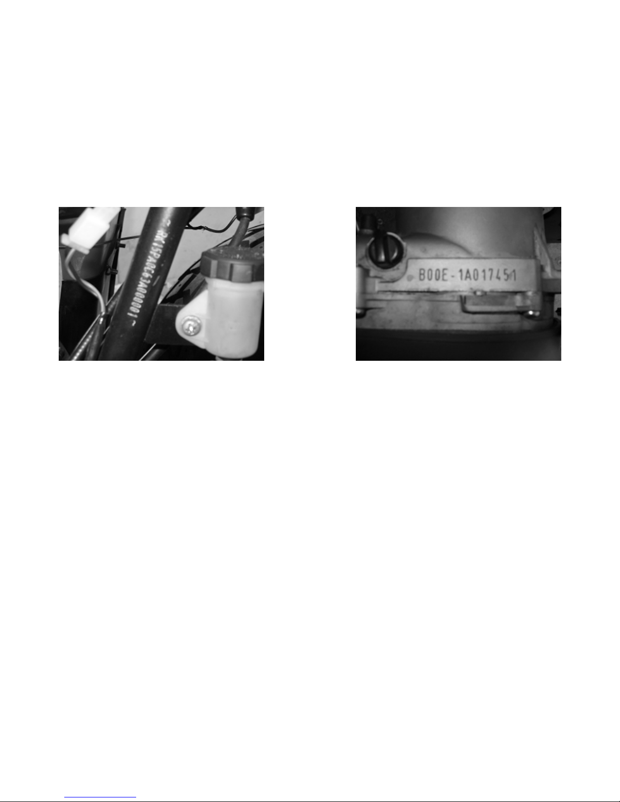
2.3 FUEL TUBE
Inspect the fuel lines for deterioration, damage or
leakage and replace any parts if necessary.
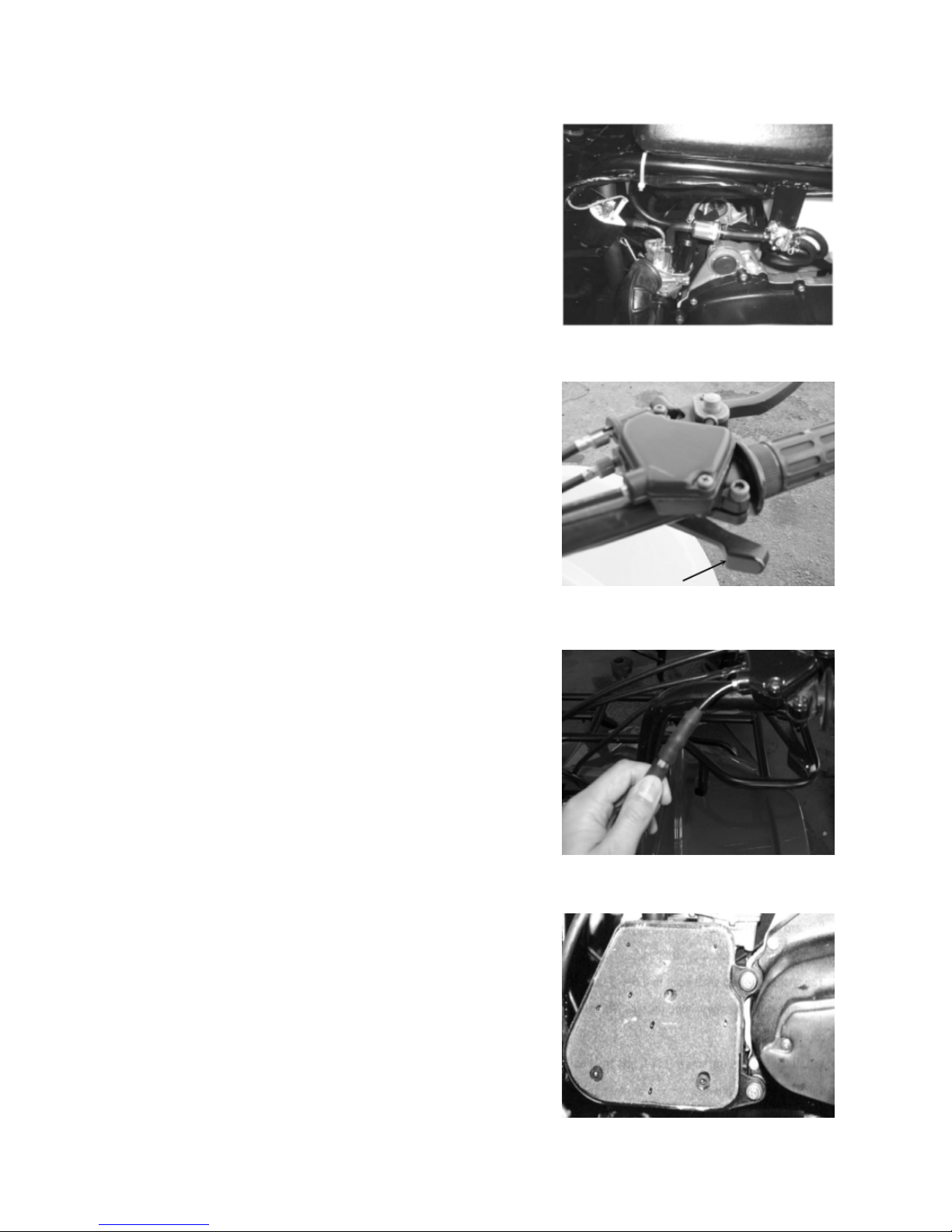
2.4 THROTTLE OPERATION
Inspect throttle lever for smooth full opening and
automatic full closing in all steering positions.
Inspect if there is no deterioration, damage or kinking
in the throttle cable, replace it if occur any damage.
Check the throttle lever, free play is 5-10 mm at the tip
of the throttle lever.
Disconnect the throttle cable at the upper end.
Lubricate the cable with commercially lubricant to
prevent from premature wear.
2.5 THROTTLE CABLE ADJUSTMENT
Slide the rubber cap of the adjuster off the throttle
Housing, loosen the lock nut and adjust the free play
of the throttle lever by turning the adjuster on the throttle
housing. Inspect the free play of the throttle lever.
2.6 AIR CLEANER
Unscrew the air cleaner cover screws.
Pull out the air filter element from the air cleaner case.
Wash the element in non-flammable solvent, squeeze
out the solvent thoroughly.
Let it dry.
Soak the filter element in gear oil and then squeeze
out the excess oil.
Install the element into air cleaner carefully.
7