FUEL
S
YST
EM
CARBURETOR
r
-
~=
=
___
-_
-_-_
-_-
_-_-
_-
::
_-
___
~
-.
~
_<?i
_-_
-_-_
~
~
~
-_
~~~
___
=
~
_-
_
~
=
=~
~
-:
I , I
I , '
!
i
~i
I I I
I : : :
: : I :
I t I I
I I I I
I : I I
I I I 1
I I I
Starter
:n:
plunger:
:
, :
, ,
Throttle
valve
Float
,
I I
I '
I :
, ,
Starter
jet
Fuel
..
Air
CJ
Mixture
¢ri
Jet
needle
Pilot
jet
Ring
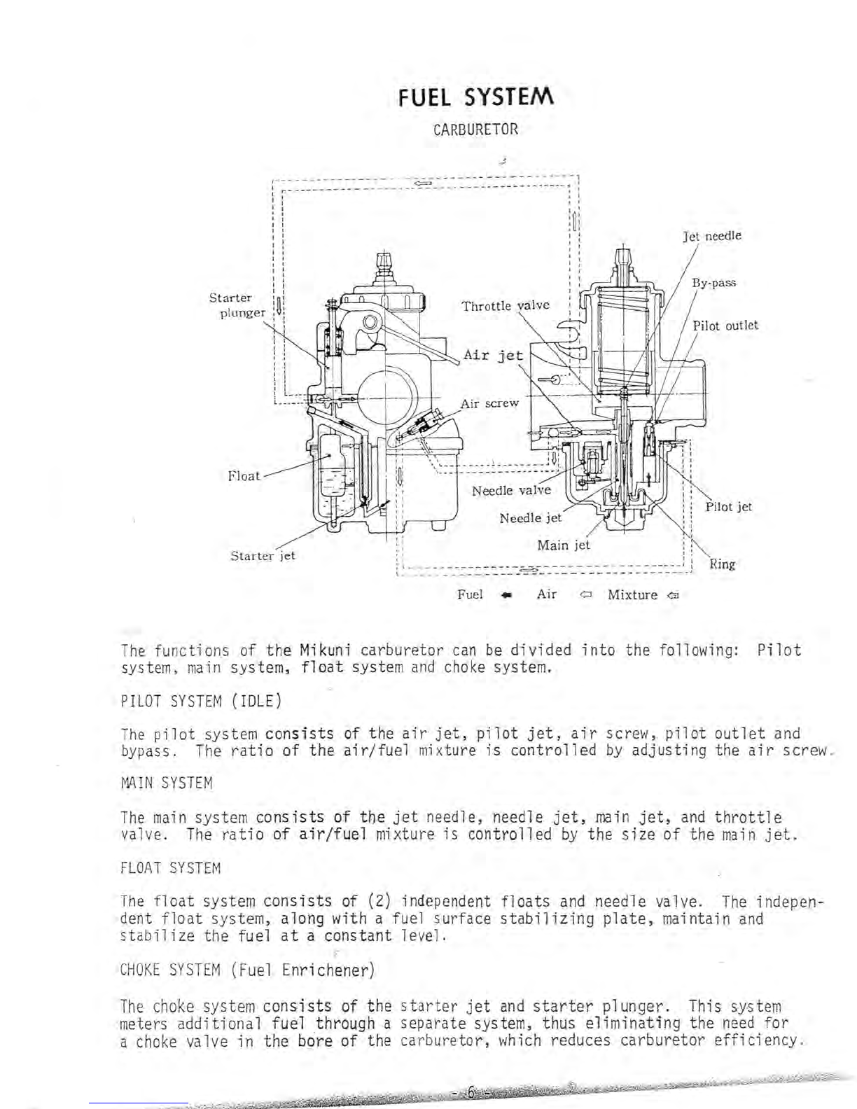
The
function,s of the
Mikuni
carburetor
can
be
divided
into
the following:
Pilot
system,
main
system,
float
system
and
choke
syste~.
PILOT
SYSTEM
(IDLE)
The
pilot
system
con
s
ists
of the
air
jet,
pilot
jet,
air
screw,
pilot
outlet
and
bypass.
The
ratio
of the
air/fuel
mixture
is
controlled
by
adj.ustingthe
air
screw.
MA.IN
SYSTEM
The
main
system
consists
of the
jet
needle, needle
jet,
main
jet,
and
throttle
valve.
The
ratio
of
air/fuel
mixture
is
controlled
by
the
size
of the
main
jet.
FLOAT
SYST
EM
The
float
system
consists
of (2) independent
floats
and
needle valve.
The
indepen-
dent
float
system, along with a fuel surface
stabilizing
plate,
maintain
and
stabilize
the fuel
at
a constant
le
v
el.
CHOKE
SYSTEM
(Fuel Enrichener)
The
choke
system
consists
of the
starter
jet
and
starter
plunger. This system
meters additional fuel through a separate system, thus
eliminating
the
need
for
a
choke
valve in the
bcire
of the carburetor,
which
reduces carburetor
efficiency.