Johnny's Selected Seeds 6791 User manual

Copyright © 2022 Johnny’s Selected Seeds. All rights reserved. 1
SEED BREEDERS, GROWERS, AND MERCHANTS SINCE 1973
955 Benton Ave., Winslow, ME 04901 •Phone: 1-877-564-6697 •Fax: 1-800-738-6314
Email: [email protected] •Web Site: Johnnyseeds.com
Materials Included
•(1) 20" exhaust shutter fan
•(1) 24" power shutter
•(1) Motor
•(1) Motor mount bracket
•(1) Motor arm
•(4) #8-32 X 3/8" screws
•(3) S-hooks
•(1) Chain
•(2) Return springs
•(1) Line voltage thermostat
Tools Needed
•Measuring tape
•Level
•Drill
•¼" & 1/8" drill bits
•¼" wrench
•Phillips head screwdriver
•5/32" Allen wrench or hex key
•Pencil
•8' ladder
ASSEMBLY INSTRUCTIONS
STEP 1: MOUNTING THE EXHAUST SHUTTER FAN
1.1 Frame out a 21" x 21" opening near the peak of the
tunnel for the 20" shutter fan.
1.2 Insert the shutter fan into the opening from the inside
of the tunnel so the shutter louvers are facing outward.
Note: The shutter louvers should be able to open and
close freely.
1.3 Secure the shutter fan to the end wall frame using
screws and the pre-drilled holes along the flange (see
figure 1).
Note: Use #14 X 1" Tek screws for attaching to metal
end walls, and #12 X 1½" Woodmate screws for
attaching to wood.
Plug the cord into a 115 AC grounded outlet that
meets national, regional, and local codes.
Note: Be sure to create a drip loop with the electrical
cord to prevent water from entering the thermostat
housing.
#6791 Automatic Ventilation Kit
Bobcat Tunnel Accessory
Assembly Instructions
Figure 1: Exhaust shutter fan installed.
Woodmate screws

Copyright © 2022 Johnny’s Selected Seeds. All rights reserved.
2 SEED BREEDERS, GROWERS, AND MERCHANTS SINCE 1973
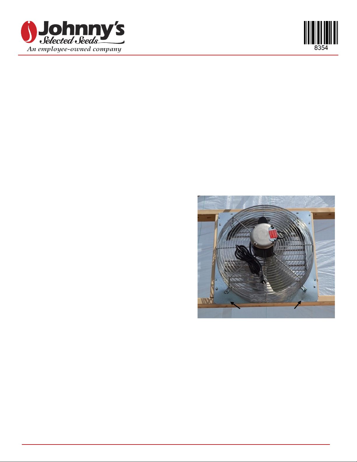
STEP 2: MOUNTING THE MOTORIZED POWER SHUTTER
2.1 Frame out a 25" x 25" opening near the peak on the
opposite end of the tunnel to mount the motorized power
shutter. You will need to add one vertical brace that goes
from the bottom-center of the shutter frame, down to the
top of the door frame. This will be used to mount the
motor below the shutter (see figure 2).
2.2 Insert the power shutter into the opening from the inside
of the tunnel so the shutter louvers are facing outward
(see figure 2).
2.3 Secure the power shutter to the end wall frame using
screws and the pre-drilled holes along the flange.
Note: Use #14 X 1" Tek screws for attaching to metal
end walls, and #12 X 1½" Woodmate screws for
attaching to wood.
2.4 Attach the motor arm to the motor drive shaft by aligning
the flat edges with the socket screws and tighten them
using a 5/32" Allen wrench or hex key. Manually turn the
motor arm so that it is positioned straight up and down
(see figure 3).
2.5 Locate the horizontal center of your newly installed
shutter and make a mark on the wall frame directly below
the shutter flange with a pencil.
2.6 Measure ¾" to the right of this center line and make
another mark. This line will determine the left edge of
your motor mount bracket (see figure 4).
2.7 Measure 2" down from the bottom edge of the shutter
flange and make another mark to determine the position
of the top edge of the motor mount bracket (see figure 4).
2.8 Line the short side of the motor mount bracket up with
these marks and secure it to your structure using
#14 X 1" Tek screws or #12 X 1½" Woodmate screws
(see figure 4).
2.9 Secure the motor to the motor mount bracket using the
four #8-32 X 3/8" Phillips head screws provided.
Figure 2: Motorized power shutter installed (outside).
Figure 4: Motor mount bracket and motor installed
onto the brace between shutter and door frame.
Figure 3: Attaching the motor arm to the motor drive
shaft.
Shutter
Motor mount
bracket
Motor
Brace
2"
¾"

Copyright © 2022 Johnny’s Selected Seeds. All rights reserved.
3 SEED BREEDERS, GROWERS, AND MERCHANTS SINCE 1973
2.10 Locate the corner on the shutter where the outer flange
meets the vertical tie bar. Measure ½" to the left of this
corner and ¼" up from the bottom of the upper shutter
flange and make a mark with a pencil. Drill a hole
through the shutter flange in this location using a 1/8"
drill bit (see figure 5).
2.11 Hook one end of the return spring into the hole you just
drilled and hook the other end around the hole located
by the second louvre from the top (see figure 6).
2.12 Insert an S-hook into the first available hole below the
return spring on the tie bar (see figure 6), and attach
another S-hook to the motor arm (see figure 7). Trim the
excess chain.
Note: Connect the chain between these two S-hooks
so that there is just a slight amount of slack.
2.13 Plug the power cord into the grounded outlet on the
thermostat cord.
STEP 3: INSTALLING THE THERMOSTAT
3.1 Mount the thermostat onto your tunnel wall using
#14 X 1" Tek screws or #12 X 1½" Woodmate screws.
Note: The thermostat should be placed at a convenient
height for operation.
3.2 Plug the power cord into the grounded outlet that meets
national, regional, and local codes.
Note: Be sure to create a drip loop with the electrical
cord, to prevent water from entering the thermostat
housing.
02.04.2022 | KH, JG, ms
Figure 5: Hole drilled for attaching the return spring.
Figure 6: Return spring, S-hook, and chain placement.
Figure 7: Attaching the S-hook and chain to the
mounting arm.
Shutter
tie bar
Hole
½"
¼"
Return
spring
S-hook
and chain
Table of contents
Popular Fan manuals by other brands

Vornado
Vornado PIVOT 6-JP owner's guide

Tamarack Technologies
Tamarack Technologies CX3000 installation instructions

Field Controls
Field Controls 46261800 Replacement instructions

NuTone
NuTone LPN80F installation guide

Flex-a-Lite
Flex-a-Lite 125 installation instructions

Hunter
Hunter Exteriors 90155 owner's manual