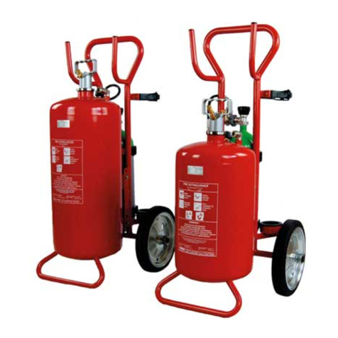
Johnson Controls ANSUL XM User manual

XM WHEELED DRY CHEMICAL
FIRE EXTINGUISHER
OPERATION AND MAINTENANCE MANUAL
002648
One Stanton Street |Marinette, WI 54143-2542, USA |+1-715-735-7411 |www.ansul.com
© 2023 Johnson Controls. All rights reserved. All specifications and other information shown were
current as of document revision date and are subject to change without notice. |Part No. S-50651-02


XM Wheeled Dry Chemical Fire Extinguisher
Operation and Maintenance Manual
(Part No. S-50651)
2023-AUG-30 REV. 02
FOREWORD
This manual is intended for use with ANSUL® XM Wheeled
Fire Extinguishers. Use this guide if you operate, recharge,
inspect, or maintain these fire extinguishers.
Fire extinguishers are mechanical devices. They need periodic
inspection and maintenance to check that the fire suppression
system is fully charged and operable and that the fire extin-
guishers are working safely and effectively.
Inspect fire extinguishers at regular intervals. Inspection
intervals can be hourly to monthly, depending on the
circumstances.
Maintain fire extinguishers annually or whenever an inspection
indicates maintenance.These fire extinguishers are pressure
vessels and must be handled carefully.
Only use genuine ANSUL® replacement components with
ANSUL® products. ANSUL® products must be serviced and
maintained by Authorized ANSUL® Distributors.
This guide is limited to the uses it describes. For other appli-
cations, contact your local Authorized ANSUL® Distributor or
Johnson Controls Technical Services Department, Marinette,
Wisconsin 54143-2542, USA.
Note: The converted metric values in this manual are provided
for dimensional reference only and do not reflect an actual
measurement.
DISCLAIMER:
Johnson Controls does not make any representations,
warranties or guarantees, expressed or implied, as to the
accuracy or completeness of the manual. Users must be aware
that updates and amendments will be made from time to time to
the manual. It is the user’s responsibility to determine whether
there have been any such updates or amendments. Neither
Johnson Controls nor any of its directors, officers, employees,
or agents shall be liable in contract, tort, or in any other manner
to any person for any loss, damage, injury, liability, cost, or
expense of any nature, including without limitation incidental,
special, direct, or consequential damages arising out of or in
connection with the use of the manual.
All instructions contained herein relate to a typical installation.
Part Number: S-50651-02
Date: 2023-AUG-30
ANSUL® and the product names listed in this material are marks and/or
registered marks. Unauthorized use is strictly prohibited.

XM Wheeled Dry Chemical Fire Extinguisher
Operation and Maintenance Manual
(Part No. S-50651)
REV. 02 2023-AUG-30
EXPLANATION OF SAFETY ALERTS
p
!DANGER
Indicates a hazardous situation in which a person will experi-
ence serious personal injury or death if the situation is not
avoided.
!WARNING
Indicates a hazardous situation in which a person could expe-
rience serious personal injury or death if the situation is not
avoided.
!CAUTION
Indicates a hazardous situation in which a person could expe-
rience minor or moderate personal injury if the situation is
not avoided.
CAUTION
Addresses practices not related to personal injury, such as
a system part malfunctioning, property damage, or system
failure.
NOTICE
Addresses general practices or observations
related to system function that are not related
to personal injury.

XM Wheeled Dry Chemical Fire Extinguisher
Operation and Maintenance Manual
(Part No. S-50651)
TABLE OF CONTENTS
REV. 02 2023-AUG-30 PAGE TOC-1
SECTION PAGE
Introduction 1 – 2
Assembly 3 – 4
Operation 5 – 6
Recharge 7 – 10
Inspection 11 – 12
Maintenance 13 – 16
Service and Repair 17 – 22

XM Wheeled Dry Chemical Fire Extinguisher
Operation and Maintenance Manual
(Part No. S-50651)
TABLE OF CONTENTS
PAGE TOC-2 REV. 02 2023-AUG-30
NOTES:

XM Wheeled Dry Chemical Fire Extinguisher
Operation and Maintenance Manual
(Part No. S-50651)
2023-AUG-30 REV. 02 PAGE 1
INTRODUCTION
INTRODUCTION
When utilized, the Occupational Safety and Health Act rules
require that “the employer shall be responsible for the inspection,
maintenance and testing of all portable extinguishers in the
workplace.” Details are provided in 29 CFR 1910.157(e) and in
Appendices A and B to Subpart L, referencing the provisions
of the latest edition of NFPA 10, “Standard for Portable Fire
Extinguishers” as guidelines. The latest edition of NFPA 10,
“Standard for Portable Fire Extinguishers” and NFPA 17 entitled
“Standard For Dry Chemical Extinguishing Systems” are available
from the National Fire Protection Association. Visit www.nfpa.org.
RESPONSIBILITY
The owner or occupant of a property in which re extinguishers
are located has an obligation for the care and use of these
extinguishers at all times. By doing so, they are contributing to
the protection of life and property. The nameplates and instruction
manual should be read and thoroughly understood by all persons
who may be expected to use extinguishers.
RECHARGE
All extinguishers shall be recharged after use or as indicated by
an inspection or when performing maintenance. Recharging is the
replacement or replenishment of the extinguishing agent. It also
includes the replenishment of the expellant gas for certain types
of extinguishers. When performing the recharging, use only those
materials specied on the nameplate. The use of other recharging
materials may impair the efciency, cause malfunction, or result in
rupture of the extinguisher that could cause injury to the operator.
Select a dry, warm, and preferably enclosed location with
atmospheric conditions of not more than 55% relative humidity
and ambient temperatures of not less than 65 °F (18 °C).
!CAUTION
When performing recharge, use only those materials specified
on the extinguisher nameplate. The use of other recharging
materials may reduce the efficiency, cause malfunction, or
result in rupture of the extinguisher that could cause injury to
the operator.
INSPECTION
“Inspection” is a “quick-check” that an extinguisher is available
and will operate. It is intended to give reasonable assurance
that the extinguisher is fully charged and operable. This is
done by seeing that it is in its designated place, that it has not
been actuated or tampered with, and that there is no obvious
physical damage or condition to prevent operation. The value of
an inspection lies in the frequency, regularity, and thoroughness
with which it is conducted. The frequency will vary from hourly to
monthly, based on the needs of the situation. Inspections should
always be conducted at regular intervals.
MAINTENANCE
Extinguishers shall be maintained at regular intervals, not more
than one year apart, or when specically indicated by an
inspection. Maintenance is a “thorough check” of the extinguisher.
It is intended to give maximum assurance that an extinguisher will
operate effectively and safely. It includes a thorough examination
and any necessary repair, recharging or replacement. It will
normally reveal the need for hydrostatic testing of an extinguisher.
HYDROSTATIC TEST
Extinguishers shall be tested hydrostatically at regular intervals
per the latest edition of NFPA 10, “Standard for Portable
Fire Extinguishers”, or more frequently when inspection or
maintenance indicates a specic need. Such tests are usually
required on extinguisher shells, cylinders, some cartridges and
some hose assemblies.
!WARNING
If at any time, an extinguisher shows evidence of corrosion or
mechanical injury, it shall be subjected to a hydrostatic pres-
sure test, or replaced. Important: Air or gas should not be
used for pressure testing as failure of a shell could be violent
and dangerous.The extinguisher shall be charged and hydro-
tested at twelve year intervals.
NOTICE
Extinguishers utilizing a cylinder that has
a US Department of Transportation (DOT)
marking shall be hydrostatically tested, or
replaced, according to the requirements of
the US Department of Transportation (DOT).
NOTICE
Cylinders (except those charged with Carbon
Dioxide) complying with Part 173.34(e) 15,
Title 49, Code of Federal Regulations, may
be hydrostatically tested every 10 years.
Refer to ANSUL® Technical Bulletin Hydrostatic Retest
Requirements for ANSUL®Pressure Vessels (Form No. F-81301,
latest revision) for additional details on requirements and the
ANSUL® Hydrostatic Test Instructions Manual (Form No. F-7602,
latest revision) for procedures.
RECORD KEEPING
Each extinguisher shall have a tag or label securely attached that
indicates the month and year the maintenance was performed
and shall identify the person performing the service. The same
record tag or label shall indicate if recharging was also performed.
At least monthly, the date the inspection was performed and the
initials of the person performing the inspection shall be recorded.
In addition to the required tag or label, a permanent le record
should be kept for each extinguisher. This le record should
include the maintenance date and the name of person or agency
performing the maintenance; the date when last recharged and
the name of person or agency performing the hydrostatic test; and
description of dents remaining after passing a hydrostatic test.
Parts of above taken from NFPA Pamphlet 10.
XM Wheeled Dry Chemical Fire Extinguisher
Operation and Maintenance Manual
(Part No. S-50651)
PAGE 2 REV. 02 2023-AUG-30
INTRODUCTION
REFERENCES
Table 1: References
References in this manual Available from
NFPA-10 “Standard for portable
fire extinguishers”
NFPA 1
Batterymarch
Park Quincy, MA
02169-7471
CGA C-1 “Methods for
hydrostatic testing
of compressed gas
cylinders”
Compressed Gas
Association
14501 George Carter
Way,
Suite 103 Chantilly,
VA 20151-1788
CGA C-6 “Standard for visual
inspection of steel
compressed gas
cylinders”

XM Wheeled Dry Chemical Fire Extinguisher
Operation and Maintenance Manual
(Part No. S-50651)
2023-AUG-30 REV. 02 PAGE 3
ASSEMBLY
ASSEMBLY
Preparing the extinguisher for placement in service
1. Remove all cord, wrapping, and banding ties. Examine the
extinguisher for concealed shipping damage.
2. Fill the dry chemical tank, as follows:
NOTICE
Certain dry chemical extinguishers are filled
before shipment.
a. Remove the rell cap and place a funnel in opening.
b. Fill the tank to its rated capacity with only the ANSUL® dry
chemical specied on the nameplate.
c. Clean the ll opening threads and the gasket seating
surface. Make sure the gasket is in place before reinstalling
the ll cap.
d. Secure the ll cap and hand tighten.
NOTICE
If the fill cap is an indicator model, be
sure the red indicator stem is in the
down position before securing fill cap. See
Figure 1.
FIGURE 1
002649
3. Remove the safety shipping cap from the tank.
4. Read the cylinder gauge. The pointer should be in the black
operating pressure range, as shown in Figure 2.
FIGURE 2
002650
!WARNING
Do not place body or head in front of cylinder valve outlet.
If valve is accidentally operated, velocity of unrestricted
escaping gas is forceful enough to cause injury, especially
about the face and head.
5. Attach the high pressure hose, using 1 1/8 in. open-end
wrench.
6. Check the visual inspection seal on the cylinder valve. If it is
broken or missing, replace it with Part No. 197. See Figure 3.
FIGURE 3
002652

XM Wheeled Dry Chemical Fire Extinguisher
Operation and Maintenance Manual
(Part No. S-50651)
PAGE 4 REV. 02 2023-AUG-30
ASSEMBLY
ASSEMBLY (Continued)
7. Check that all valve handles are ring pinned and sealed in the
operating position. See Table 1.
Table 2: Valve operating positions
Valve Handle Operating Position
Red Tank Valve Open
Green Vent Valve Closed
Blue Hose Clean-out Valve Closed
Black Dry Chemical Valve Open
8. Replace any broken or missing visual inspection seals (Part
No. 25940).
9. Check nozzle handle. It should be in the closed position. The
nozzle assembly should be on its holder.
10. Instruct personnel in the correct operation of the extinguisher.
Record the date of replacement in service in a permanent
record le.

XM Wheeled Dry Chemical Fire Extinguisher
Operation and Maintenance Manual
(Part No. S-50651)
2023-AUG-30 REV. 02 PAGE 5
OPERATION
OPERATION
To operate the extinguisher, complete the following steps:
1. Turn the cylinder valve handwheel counterclockwise to fully
open position.
FIGURE 4
002655
2. Pull off all hose, stand back about 20 ft (150-C extinguisher)
or 25 ft (350-C extinguisher).
3. Open the nozzle.
FIGURE 5
002657
NOTICE
For additional information on the proper use
and suppression applications of ANSUL®
wheeled and stationary extinguishers, we
offer hands-on fire fighting training at the
ANSUL® fire school. Visit www.ansul.com.
FLAMMABLE LIQUID SPILL FIRE
1. Direct the streams at the base of the ames with a side to side
motion.
FLAMMABLE LIQUID OR COMBUSTIBLE GAS PRESSURE
FIRE
1. Direct the stream into the source of escaping fuel using
velocity of fuel to carry extinguishing agent to point of
combustion.

XM Wheeled Dry Chemical Fire Extinguisher
Operation and Maintenance Manual
(Part No. S-50651)
PAGE 6 REV. 02 2023-AUG-30
OPERATION
NOTES:

XM Wheeled Dry Chemical Fire Extinguisher
Operation and Maintenance Manual
(Part No. S-50651)
2023-AUG-30 REV. 02 PAGE 7
RECHARGE
RECHARGE
To recharge the extinguisher after use, complete the following
steps:
1. Pull the ring pin and close the red tank valve.
2. Pull the ring pin and close the black dry chemical valve.
3. Pull the ring pin and open the green vent valve.
4. Pull the ring pin and open the blue hose clean-out valve.
5. Open the nozzle to clear hose line of dry chemical. Close the
nozzle when stream is clear of dry chemical. Do not relieve
remaining pressure at this time.
6. Close the nitrogen cylinder valve, turning the handwheel
clockwise, then hand tighten.
FIGURE 6
002658
7. Open the black dry chemical valve to clear the pick-up tube
of dry chemical.
NOTICE
A small quantity of dry chemical may
discharge from the open green vent valve
at this time.
8. Close the blue hose clean-out valve.
9. Fill the dry chemical tank, as follows:
a. Remove the ll cap and place a funnel in opening.
b. Fill the tank to its rated capacity using only the ANSUL® dry
chemical specied on the nameplate.
c. Clean the ll opening threads and gasket seating surface.
d. Examine the ll cap gasket for elasticity, cuts, or weather
checking.
e. Clean and coat the gasket lightly with a good grade of high
heat-resistant grease, then replace it.
f. Inspect the threads in the ll cap and on the ll opening,
looking for nicks, burrs, cross-threading, and rough or
feathered edges.
g. Clean and coat ll cap threads lightly with a good grade of
high heat-resistant grease.
h. Check that the gasket is in place before reinstalling the ll
cap.
i. Secure the ll cap and hand tighten.
FIGURE 7
002649
NOTICE
If the fill cap is an indicator model, be
sure the red indicator stem is in the
down position before securing fill cap.
10. Read the cylinder gauge. Note the pressure, check the
ambient temperature and refer to the Temperature Correction
Chart section of the ANSUL® Wheeled and Stationary Dry
Chemical Fire Extinguishers Operation, Inspection, Service
and Maintenance, and Recharge Manual (Part No. 79012).
Replace the cylinder if below 1500 PSI (10341 kPa) at 70 °F
(21 °C).
FIGURE 8
002667
!WARNING
Do not place body or head in front of cylinder valve outlet.
If valve is accidentally operated, the velocity of unre-
stricted escaping gas is forceful enough to cause injury,
especially about the face and head.

XM Wheeled Dry Chemical Fire Extinguisher
Operation and Maintenance Manual
(Part No. S-50651)
PAGE 8 REV. 02 2023-AUG-30
RECHARGE
RECHARGE (Continued)
11. Disconnect the high pressure hose at the nitrogen cylinder
valve using a 1 1/8 in. open-end wrench.
FIGURE 9
002664
12. Install the safety shipping cap (Part No.73066) on nitrogen
cylinder.
!WARNING
The safety shipping cap must always be in place when
removing or installing a nitrogen cylinder
13. Loosen the wing nut and swing the hose support/cylinder
clamp out of the way.
14. Remove the nitrogen cylinder.
15. Disconnect the dry chemical hose at the adaptor, below the
tee and adjacent to the black dry chemical valve.
16. Remove the ruptured visual hose inspection disc from the
face of the adaptor.
17. Install the new visual hose inspection disc. For Model 150-C,
use Part No. 14236. For Model 350-C, use Part No. 14237.
FIGURE 10
002666
18. Connect the hose to the adaptor and wrench tighten.
19. Replace the cylinder with the fully charged nitrogen cylinder.
NOTICE:
Read the cylinder gauge through the slots
in the shipping cap before installation. The
pointer should be in black operating range.
20. Position the cylinder to facilitate installation of the high
pressure nitrogen hose.
21. Install the cylinder clamp and tighten the wing nut.
22. Remove the safety shipping cap from the nitrogen cylinder.
Retain the shipping cap for future use
!WARNING
Do not place body or head in front of cylinder valve outlet.
If valve is accidentally operated, the velocity of unre-
stricted escaping gas is forceful enough to cause injury,
especially about the face and head.
23. Connect the high pressure hose, using a 1 1/8 in. open-end
wrench.
FIGURE 11
002651

XM Wheeled Dry Chemical Fire Extinguisher
Operation and Maintenance Manual
(Part No. S-50651)
2023-AUG-30 REV. 02 PAGE 9
RECHARGE
RECHARGE (Continued)
24. Check the visual inspection seal. If it is missing or broken,
replace it with Part No. 197.
FIGURE 12
002652
25. Coil the hose. Start the rst loop clockwise and complete it by
placing over the hose support.
FIGURE 13
002668
26. Make a second, anticlockwise loop. The hose must pass
behind the loop to make the reverse loop.
FIGURE 14
002669
27. Alternate between clockwise and anticlockwise loops. Follow
the previous two steps until the entire hose is coiled on the
support. Place nozzle on the holder.
FIGURE 15
002670
28. Check the nozzle handle. It should be forward in the closed
position.
FIGURE 16
002654
29. Return all valves to operating position:
Table 3: Valve operating positions
Valve Handle Operating Position
Red Tank Valve Open
Green Vent Valve Closed
Blue Hose Clean-out Valve Closed
Black Dry Chemical Valve Open
30. Insert the ring pins through the valve handles and seal with
visual inspection seals, Part No. 25940.
31. Notify operating personnel that the extinguisher is back in
service.
32. Record the date of recharge on the tag (Part No. 2364) afxed
or attached to the extinguisher and in your permanent le
record in accordance with company, local, state, or federal
codes, regulations, or standards.

XM Wheeled Dry Chemical Fire Extinguisher
Operation and Maintenance Manual
(Part No. S-50651)
PAGE 10 REV. 02 2023-AUG-30
RECHARGE
NOTES:

XM Wheeled Dry Chemical Fire Extinguisher
Operation and Maintenance Manual
(Part No. S-50651)
2023-AUG-30 REV. 02 PAGE 11
INSPECTION
INSPECTION
To provide reasonable assurance that the extinguisher is
fully charged and operable, inspections should be conducted
at monthly intervals as follows:
1. Check that the extinguisher is in its designated location.
2. Note the general appearance of the extinguisher. Check for
mechanical damage or corrosion.
NOTICE
On the indicator fill cap models, check the
red indicator stem. If it is in the up position,
a complete maintenance examination must
be performed.
FIGURE 17
002673
3. Check all nameplates for readability.
4. Check the visual inspection seal on the nitrogen cylinder
valve. A broken or missing seal may indicate unreported
operation or tampering with extinguisher.
FIGURE 18
002652
5. Read the cylinder gauge. The pointer should be in black
operating pressure range.
FIGURE 19
002650
6. Check all valve handles are ring pinned and sealed in the
operating position:
Table 4: Valve operating positions
Valve Handle Operating Position
Red Tank Valve Open
Green Vent Valve Closed
Blue Hose Clean-out Valve Closed
Black Dry Chemical Valve Open
7. If any visual inspection seals are broken or missing, replace
them with Part No. 25940.
8. Rotate the wheels to test the lubrication of bearings. If the
wheels do not revolve smoothly, pressure lubricate the
bearings through grease ttings on the hub.
9. Inspect the nozzle for obstructions. Operate the nozzle handle
to check free movement. Return the nozzle to the holder.
Check that the nozzle handle is forward in the closed position.
FIGURE 20
002654
10. Record the date of inspection, if required.

XM Wheeled Dry Chemical Fire Extinguisher
Operation and Maintenance Manual
(Part No. S-50651)
PAGE 12 REV. 02 2023-AUG-30
INSPECTION
NOTES:

XM Wheeled Dry Chemical Fire Extinguisher
Operation and Maintenance Manual
(Part No. S-50651)
2023-AUG-30 REV. 02 PAGE 13
MAINTENANCE
MAINTENANCE
To make sure that the extinguisher operates effectively and safely,
maintenance must be conducted semi-annually on stationary
extinguishers and annually on wheeled extinguishers, or when
specically indicated by an inspection.
If a questionable condition exists, see the Service and Repair
section of this manual, and familiarize yourself with that section
before performing maintenance.
NOTICE
The regulators must be tested annually,
using the improved regulator test kit (Part No.
16171). For proper procedures refer to the
manual (Part No. 53141) which is supplied
with the kit.
1. Check that the extinguisher is in its designated area.
2. Note the general appearance of the extinguisher and check
for mechanical damage or corrosion.
3. Check the nameplates for readability, corrosion, or looseness.
4. Read the nitrogen cylinder gauge, note pressure, check the
ambient temperature, and refer to the Temperature Correction
Chart section of the ANSUL® Wheeled and Stationary Dry
Chemical Fire Extinguishers Operation, Inspection, Service
and Maintenance, and Recharge Manual (Part No. 79012).
Replace the cylinder if below minimum pressure. If you need
to replace the cylinder, see Returning the extinguisher to
service after use in the Recharge section of this document
for instructions
FIGURE 21
002667
5. Remove high pressure hose from nitrogen cylinder valve.
FIGURE 22
002664
!WARNING
Do not place body or head in front of nitrogen cylinder
valve outlet. If valve is accidentally operated, velocity of
unrestricted escaping gas is forceful enough to cause
injury, especially about the face and head.
6. Install the safety shipping cap (Part No. 73066) on the
nitrogen cylinder.
!WARNING
Safety shipping cap must always be in place when
removing or installing a nitrogen cylinder.

XM Wheeled Dry Chemical Fire Extinguisher
Operation and Maintenance Manual
(Part No. S-50651)
PAGE 14 REV. 02 2023-AUG-30
MAINTENANCE
MAINTENANCE (Continued)
7. Disconnect the nitrogen hose from the regulator to the tank
inlet and check interior of hose coupling for any signs of dry
chemical residue. If dry chemical residue is present, see
Service and repair, Table 8. Perform corrective action as
indicated – “Residual dry chemical in nitrogen hose coupling.”
FIGURE 23
002675
NOTICE
It may be necessary to remove the hose
and nozzle from its support in order to gain
access to the nitrogen tank inlet.
8. If no dry chemical residue is present, reconnect the nitrogen
hose to the tank inlet and the regulator and wrench tighten.
Complete the remaining maintenance steps.
9. Remove the safety shipping cap from the nitrogen cylinder.
Retain shipping cap for future use.
!WARNING
Do not place body or head in front of nitrogen cylinder
valve outlet. If valve is accidentally operated, velocity of
unrestricted escaping gas is forceful enough to cause
injury, especially about the face and head.
10. Connect the high pressure hose to the nitrogen cylinder valve,
using a 1 1/8 in. open-end wrench.
FIGURE 24
002651
11. Check the dry chemical tank by completing the following
steps:
a. Remove the ll cap and check the pressure relief vent (in
cap) for obstructions.
FIGURE 25
002679
b. Examine the ll cap gasket for elasticity, cuts, or weather
checking. Clean and coat the gasket lightly with a good
grade of high heat-resistant grease, then replace.
c. Inspect the threads in the ll cap and on the ll opening
for nicks, burrs, cross-threading, and rough or feathered
edges. Clean and coat the ll cap threads lightly with a
good grade of high heat-resistant grease.
d. Make sure the tank is only lled with free-owing ANSUL®
dry chemical to a level of not more than 6 in. (15 cm) from
the bottom of the ll opening.
FIGURE 26
002681
NOTICE
Do not replace fill cap at this time.
12. Examine the nozzle opening for obstructions.
13. Operate the nozzle handle to check for freedom of movement.
Replace the nozzle on holder.
Table of contents
Other Johnson Controls Fire Extinguisher manuals