Johnson Electric Nanomotion AB1A User manual
D/N: AB1A458000-00 REV: F December 2011
Nanomotion Ltd. POB 623, Yokneam 20692, Israel
Tel: 972-73-2498000 Fax: 972-73-2498099
Web Site: www.nanomotion.com
E-mail: nano@nanomotion.com
AB1A Driver
User Manual

Nanomotion Ltd. Page 2 of 29
Copyright
This document contains proprietary information of Nanomotion Ltd., and Nanomotion
Inc., and may not be reproduced in any form without prior written consent from
Nanomotion Ltd. and Nanomotion Inc.
No part of this document may be reproduced, translated, stored in a retrieval system or
transmitted in any form and by any means, electronic, mechanical, photographic,
photocopying, recording, or otherwise, without the written permission of Nanomotion Ltd.
Information provided in this document is subject to change without notice and does not
represent a commitment on the part of Nanomotion Ltd.
Copyright June 2001, Yokneam, Israel. All rights reserved.
All products and company names are trademarks or registered trademarks of their
respective holders.
Limited Warranty
Nanomotion Ltd. (hereinafter NM) warrants the product (other than software)
manufactured by it to be free from defects in material and workmanship for a period of
time of one year (except those parts normally considered as consumable/expendable
components such as motor conditioning brushes). The warranty commences thirty (30)
days from the date of shipment.
NM warrants those parts replaced under warranty for a period equal to the remaining
warranty coverage of the original part.
NM’s sole and exclusive obligation under this warranty provision shall be to repair, or at
its sole option exchange defective products or the relevant part or component, but only if:
(i) the Purchaser reports the defect to NM in writing and provides a description of the
defective product and complete information about the manner of its discovery within ten
(10) days of its discovery; (ii) NM has the opportunity to investigate the reported defect
and determines that the defect arises from faulty material, parts or workmanship; and (iii)
the Purchaser returns the affected product to a location designated by NM. These
provisions constitute the exclusive remedy of the Purchaser for product defects or any
other claim of liability in connection with the purchase or use of NM products.
This warranty policy applies only to NM products purchased directly from NM or from an
authorized NM distributor or representative.
This warranty shall not apply to (i) products repaired or altered by anyone other than
those authorized by NM; (ii) products subjected to negligence, accidents or damage by
circumstances beyond NM control; (iii) product subjected to improper operation or
maintenance (i.e. operation not in accordance with NM Installation Manuals and/or
instructions) or for use other than the original purpose for which the product was
designed to be used.
NM shall not in any event have obligations or liabilities to the Purchaser or any other
party for loss of profits, loss of use or incidental, increased cost of operation or delays in
operation, special or consequential damages, whether based on contract, tort (including
negligence), strict liability, or any other theory or form of action, even if NM has been
advised of the possibility thereof, arising out of or in connection with the manufacture,
sale, delivery, use, repair or performance of the NM products. Without limiting the
generality of the preceding sentence, NM shall not be liable to the Purchaser for
personal injury or property damages.

CE Compliance
Nanomotion Ltd. Page 3 of 29
CE Compliance
This product has been tested for Electric Safety and Electromagnetic
Compatibility and found to be in compliance with the following directives
and standards:
EMC Council Directive 89/336/EEC
Safety Council Directive 73/23/EEC
EN 55011:1998 + A1:1999
EN 61000-6-2:1999
EN 61010-1:1993 + A2:1995

Table of Contents
Nanomotion Ltd. Page 4 of 29
Table of Contents
1AB1A DESCRIPTION ..................................................................................................8
1.1 General ........................................................................................................................8
1.2 Main Features ..............................................................................................................8
1.3 Operating Principles.....................................................................................................9
2CONNECTIONS AND I/O SETTINGS........................................................................11
2.1 AB1A Front Panel.......................................................................................................11
Front Panel Connectors..............................................................................................112.1.1
Front Panel Indicators ................................................................................................12
2.1.2
2.2 Motion Controller/Joystick Connection........................................................................12
Differential Analog Connection ...................................................................................122.2.1
Joystick Connection....................................................................................................152.2.2
2.3 Cable Connections.....................................................................................................16
Shielding ....................................................................................................................162.3.1
2.4 Motor Connections .....................................................................................................16
Motor Cable Length....................................................................................................162.4.1
2.5 Opto-isolated Inputs ...................................................................................................17
Voltage Source Configuration.....................................................................................182.5.1
2.6 Fault Output................................................................................................................19
2.7 Before Operating the Motor........................................................................................19
3THERMAL ENVELOPE OF PERFORMANCE (EOP)................................................20
3.1 Description.................................................................................................................20
3.2 Stage Heat Dissipation Consideration ........................................................................20
3.3 Thermal EOP for HR Motor Driven by AB1A, AB2, AB4 Drivers.................................21
4AB1A OPERATION ...................................................................................................23
4.1 Operation Modes........................................................................................................23
Velocity Mode Operation ............................................................................................234.1.1
Step Mode operation..................................................................................................234.1.2
4.1.2.1Enabling the Step Mode .............................................................................................23
Gate Mode Operation.................................................................................................234.1.3
4.1.3.1Enabling the Gate Mode.............................................................................................24
4.2 Using the AB1A to Drive LS Motors............................................................................24
5SPECIFICATIONS .....................................................................................................25
5.1 Parameters and Conditions........................................................................................25
5.2 AB1A Layout ..............................................................................................................27
5.3 AB1A Pin Arrangement ..............................................................................................28

List of Abbreviations
Nanomotion Ltd. Page 5 of 29
List of Figures
Figure 1: AB1A Block Diagram .........................................................................................9
Figure 2: Schematic Diagram of the Output Stage with an Internal LC Card...................10
Figure 3: AB1A Driver Box Front Panel...........................................................................11
Figure 4: Differential Analog Input Connection................................................................13
Figure 5: Non-Differential (single-ended) Analog Input Connection.................................14
Figure 6: Joystick Connection.........................................................................................15
Figure 7: Opto-Isolated Input Interface ...........................................................................17
Figure 8: Jumper 1 Configuration....................................................................................18
Figure 1: Motor Velocity vs. Command...........................................................................21
Figure 2: Motor Force vs. Velocity at the Various Work Regimes (a-g)...........................22
Figure 9: AB1A Layout....................................................................................................27
List of Tables
Table 1: EOP Table for HR Motors Driven by AB1A, AB2, AB4......................................22
Table 1: AB1A Power Consumption................................................................................25
Table 2: Electrical Specifications ....................................................................................25
Table 3: Physical dimensions .........................................................................................25
Table 4: Environmental Conditions.................................................................................26
Table 5: Analog Input Specifications...............................................................................26
Table 6: Control Terminal Pin Out...................................................................................28
Table 7: Motor Output Port Pin Out.................................................................................28
Table 8: I/O Connector Pin Out.......................................................................................29

List of Figures
Nanomotion Ltd. Page 6 of 29
List of Abbreviations
A
Ampere
AC
Alternating Current
DC
Direct Current
LC
Coil Capacitor Resonance Circuit
LED
Light Emitting Diode
mA
Milliampere
mW
Milliwatt
TTL
Transistor-Transistor Logic
Vrms
Volts Root Mean Square

New Edition Remarks
Nanomotion Ltd. Page 7 of 29
New Edition Notes:
This edition is released to reflect the following changes:
1. New mode of operation has been added to the
driver: Gate Mode (for more details see Section
4.1.3). This new feature is available in drivers
bearing serial numbers 4800 and forward.
2. CE compliance section has been revised.
Other changes to the manual are primarily editorials, aiming to make the
manual a more user-friendly one.

AB1A Description
Nanomotion Ltd. Page 8 of 29
1AB1A Description
1.1 General
The AB1A is a single-axis Amplifier Box designed to drive up to 32 motor
elements in parallel.
The AB1A Card consists of DC/DC converters that provide the voltages
necessary to operate the amplifier circuit: +5V, ±12V, +3.3V. In addition, the
card contains two LED indicators and the external interface connectors for the
INPUT, MOTOR, and I/O signals.
The system configuration may require an LC Card that is connected either
internally to the AB1A Card, or externally in a separate LC Box. If the LC Card
connection is external, then it is required to connect an adapter card to the
AB1A. The adapter card shorts the necessary pins to enable the connection of
the external LC Card.
1.2 Main Features
High precision (11 bits) control of the power output stage
Drives up to 32 Nanomotion motor elements in parallel
Three modes of operation: Velocity Mode, Step Mode, and
Gate Mode
Interfaces with an Analog command
Discrete inputs enable feedback from external sources, such as
limit switches, emergency stop command, etc.
LED indicators
Reduced sensitivity to cable length and capacitance
Compact dimensions

AB1A Description
Nanomotion Ltd. Page 9 of 29
1.3 Operating Principles
The AB1A Driver Box comprises the AB1A main card and an LC card. The
AB1A Card converts the analog input command signal into a corresponding
PWM square wave output signal that is fed to the LC Card. The LC Card
produces the sine wave output voltage that drives the motor.
The LC Card type and configuration depends on the number of motor elements
driven.
For 1 to 16 elements, the LC circuit is internal to the AB1A
For 32 elements, the LC circuit is external to the AB1A (LC
Box)
An internal DC-to-DC converter that is fed from an external +48V power supply
supplies the required DC voltages.
Figure 1 illustrates a typical application of the AB1A Driver Box.
Figure 1: AB1A Block Diagram
The motor has three terminals: “UP” (red wire), “DOWN” (white wire) and
“COMMON” (black wire). The voltage applied between the “UP” and the
“COMMON” terminals causes the motor to move in one direction, while voltage
applied between the “DOWN” and the “COMMON” terminals causes the motor
to move in the opposite direction.
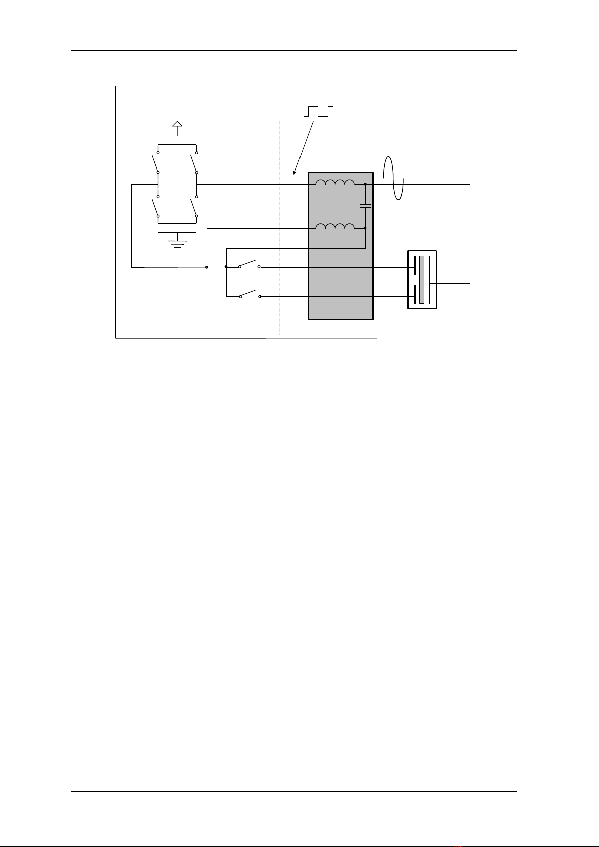
Figure 2 is a schematic drawing of the power output.
Operating Principles
Nanomotion Ltd. Page 10 of 29
+48v
H-BRIDGE
DIRECTION
CONTROL
NANOMOTION
MOTOR
COMMON
UP
DOWN
"Common"
"Phase"
"Up"
"Down"
LC Card
AC output that drives
the motor
AB1A
PWM - Square wave on
the amplifier output
Figure 2: Schematic Diagram of the Output Stage with an Internal LC Card
Table of contents


