JOVE RJ1.1 User manual

JOVE
RJ1.1 Antenna Kit
Assembly Manual

1
Radio JOVE
RJ1.1 Antenna Kit
Assembly Manual
March 1999
Antenna Kit and Manual
Developed for NASA Radio JOVE Project
by
Chuck Higgins
Francisco Reyes
Wes Greenman
Jim Gass
Thomas D. Carr
And the Radio JOVE Project Team

2

3
Contents
Theory of Operation --------- -------------------------------- 5
Site Requirements ------------ -------------------------------- 5
Time Requirements ---------- -------------------------------- 5
Dipole Array Schematic ----- -------------------------------- 6
Components ------------------- -------------------------------- 8
Tools --------------------------- ------------------------------- 10
Parts List ---------------------- ------------------------------- 10
Assembly ---------------------- ------------------------------- 11
Field Setup -------------------- ------------------------------- 17

4

5
Theory of Operation - Antenna
The antenna intercepts weak electromagnetic waves that have traveled some 500
million miles from Jupiter to the Earth or 93 million miles (1 Astronomical Unit = 1 AU)
from the Sun. When these electromagnetic waves strike the wire antenna, a tiny radio
frequency (RF) voltage is developed at the antenna terminals. Signals from each single
dipole antenna are brought together with a power combiner via two pieces of coaxial
cable. The output of the power combiner is delivered to the receiver by another section of
coaxial transmission line.
Site Requirements
The antenna system requires a fair-sized area for setup: minimum requirements
are a 25 x 35 ft. flat area that has soil suitable for putting stakes into the ground. Since the
antenna system is sensitive to noise it is best not to set it up near any high tension power
lines or close to buildings. Also for safety reasons, please keep the antenna away from
power lines during construction and operation. The best locations are in rural settings
where the interference is minor. Since many of the observations occur at night it is wise
to practice setting up the antenna during the day to make sure the site is safe and easily
accessible.
Construction Time Estimates
Measuring and Cutting Wire and Cable 30 min.
Wrapping Insulators 30 min.
Preparing and Soldering Coax 60 min.
Installing Toroids and Connectors 60 min.
Assembling the Mounting Hardware 60 min.
Field Setup (first time) 45 min.
Total Time 4.75 hrs.

6

7

8
Components
The antenna is composed of several types of components (Figure 1) including
wire, coaxial cable, connectors, insulators, rope, supports, and hardware.
Figure 1a and 1b. Antenna Parts.
Wire – the copper wire is used for the antenna elements. We are constructing two
identical half-wave dipole antennas and phasing them together with feed line. The entire
length of the dipole is therefore, equal to the length of 1/2 of the wavelength (λ) of
radiation to be detected. Thus each side of the dipole antenna is 1/4 wavelength long (See
Schematic on previous pages). Since the Radio JOVE receiver is tuned to the frequency
of 20.1 MHz (M=mega=106), the wavelength is 48.968 feet (14.925 meters). A useful
formula for calculating the half-wavelength for an "ideal" dipole in free space for a
specific frequency is:
λ/2 (in feet) = 492 / frequency (in MHz)
or λ/2 (in meters) = 150 / frequency (in MHz).
For practical antennas, however, the measured values are smaller than the “ideal” values.
This is a result of resistance in the wire and end effects of the dipole. These two
properties effectively shorten the length at which the wire will resonate or most
effectively receive radiation at a frequency of 20.1 MHz. To calculate the "practical"
half-wavelength of antenna use the formula:
λ/2 (in feet) = 468 / frequency (in MHz)
or λ/2 (in meters) = 142.5 / frequency (in MHz).

9
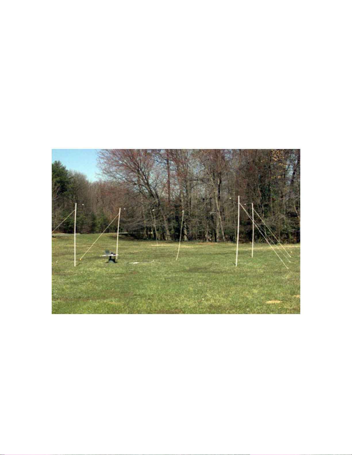
For the antenna to be an effective receptor of signals, the wire dipoles must be
mounted horizontally above the ground by about λ/4 feet (8-12 feet [2.44 - 3.66 m] is
acceptable). This is accomplished by attaching the wire to poles held up by support rope
(see below).
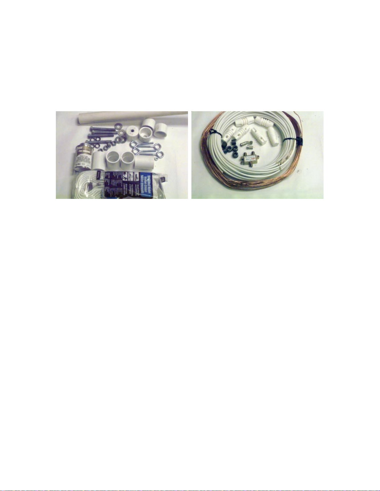
Coaxial Cable (coax) – the coaxial transmission cable is used to feed the signal
intercepted (or collected) by the antenna to the receiver. Therefore the coaxial cable must
be attached to the antenna wire by solder joints. The coaxial cable has a center conductor
surrounded by a dielectric insulator (polyethylene) and a copper braided shielding. These
help conduct the signal from the antenna to the receiver with a minimum of loss of signal.
Because the cable is not a perfect conductor, the speed at which the signal propagates
along the wire depends on the type of dielectric insulation used in the cable. For the coax
included in your kit, the velocity factor (Vf) is 66%. Therefore the proper lengths for
cutting the coax must take this factor into account.
Connectors – the connectors used for the Radio JOVE are called F-type connectors and
can be manually twisted onto the ends of the coax line. These connectors are used to
connect the cables to the power combiner and to the antenna input on the JOVE receiver.
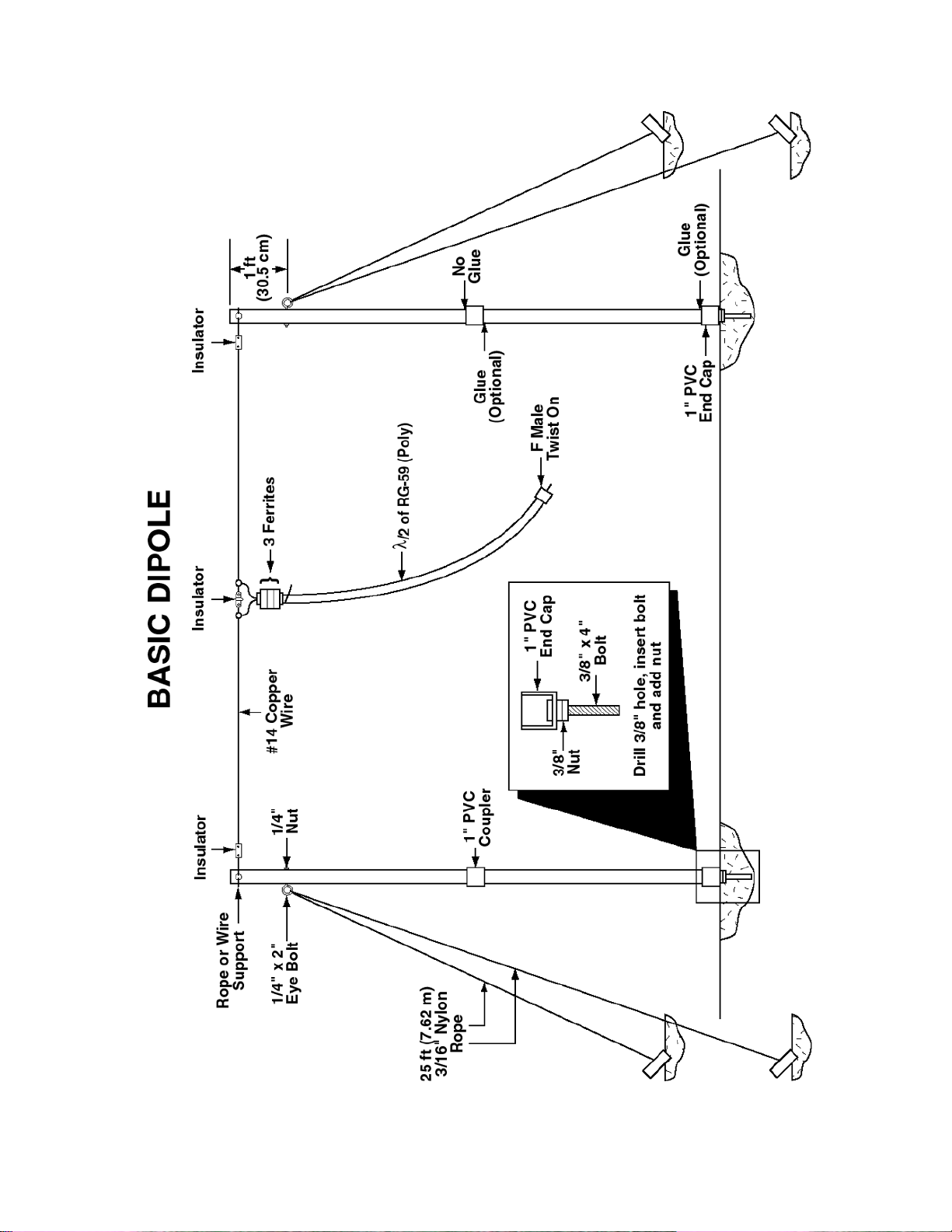
Insulators – insulators are needed to keep the antenna from shorting the received signals
to ground. Six insulators are needed for the antenna, one in the middle of each dipole, and
one on each end. Insulators are usually plastic or ceramic cylinders with holes cut in each
end for the wire and rope supports.
Support poles – PVC piping is suggested for the antenna support poles. It is a cheap and
lightweight support structure that is portable and effective.
Rope – rope is used to support the antenna poles as guy lines for each support pole.
Hardware – hardware in the form of bolts and nuts are used to make it easy to support
the antenna. Bolts are used as foot pegs to help keep the poles in place and eyebolts are
used to help attach the guy lines to the poles.
Toroids – the magnetic toroids are needed for the antenna assembly to restrict current
flow along the outer surface of the coaxial cable shielding. This allows for optimal
reception by creating a better antenna pattern.

10
Tools
Soldering Iron (RS 64-2070C)
Solder, 60/40, 0.050 in diameter rosin core (RS 64-006), or finer
Wire Cutters (RS 64-1833) and Wire Strippers (RS 64-2129)
X-actoKnife (or equivalent)
Scissors
Tape measure (at least 12 ft. is best)
Small screwdriver
Crescent Wrench
Pliers
Drill with > 1/4 in. and > 3/8 in. drill bit
Radio JOVE Antenna Parts List
Parts included with the Radio JOVE Antenna Kit Parts Checklist
1 50 ft. (15.24 m) #14 Gauge Bare Copper Wire (7-stranded)
1 70 ft. (21.336 m)RG59U Coaxial Cable (Beldon 8241)
4 PVC End Insulators (cylinders)
2 Plastic Center (dogbone) insulators
4 Twist-on F-connectors
1 Power combiner / splitter (2-to-1)
6 Ferrite toroids
Parts necessary but NOT included with the Radio JOVE Antenna Kit
1 100 ft. (30.48 m) x 3/16 in. Nylon Rope
4 10 ft. (3.048 m) x 1 in. PVC pipes (Sch 40)
4 1 in. PVC End Caps
4 1 in. PVC Couplers
4 3-4 in. x 3/8 in. Bolts
4 3/8 in. Nuts
4 3/8 in. Flat Washers and Lock Washers (optional)
4 3 in. x 1/4 in. Eye Bolts
4 1/4 in. Nuts
1 Small can of PVC Cement (optional)
6 Tie wraps (optional)
8 Tent stakes

11
Assembling the Antenna
Measuring and Cutting Wire and Rope
Measure and cut the proper lengths of the bare copper wire, the coaxial cable, and the
rope. A good long hallway is excellent for this job. Use tape on the floor to mark the
lengths for each of the different cuts.
1. oCut 4 sections of the copper wire to 12 ft. 4 in. (3.76 m).
Use the formula for practical antennas and calculate λ/2 length for the wire.
λ/2 (practical) = 23.28 ft. or 23 ft. 3 in.
Divide by 2 to calculate λ/4
λ/4 (practical) = 11.64 ft. or 11 ft. 7.7 in.
Subtract 1.5 in. to account for the 3 in. center insulator
λ/4 (corrected) = 11.52 ft. or 11 ft. 6 in.
Add 5 in. to each end of the wire for wrapping the insulators
Proper Wire Length = 12.35 ft. or 12 ft. 4 in.
2. oCut 2 sections of the coaxial cable to λ/2 = 16.2 ft. (4.94 m)
Use the formula above for the ideal antenna wavelength and calculate λ/2 for the
coaxial cable.
λ/2 (coax) = 24.48 ft. or 24 ft. 5 in.
Multiply by the velocity factor (Vf= 66%) to calculate the proper coax length
λ/2 (corrected) = 16.15 ft. or 16 ft. 2 in.
3. oCut 1 section of coax to λ= 32.3 ft. or 32 ft. 4 in. (9.85 m).
Wrapping the Insulators
1. oUsing the copper wire, thread the extra 5 in. (12.7 cm) through the hole in the
insulators and wrap it back on itself. If necessary use pliers to wrap the wire tight.
2. oWrap the ends of two copper wires around one insulator (center insulator) and
then the other ends around two separate insulators (end insulators). The result should
look like the examples in Figure 2.
3. oRepeat this procedure for the second dipole. A measurement of the total length
of the antenna (from one end insulator to the other end insulator) should be 23 ft. 3 in.
(7.09 m).

12
Figure 2a and 2b. Wrap the center and end insulators with the antenna wire.
Preparing and Soldering the Coax
1. oUsing the end of one of the λ/2 pieces of coax, strip back (remove) the outer
covering about 4 - 5 inches (10 - 12 cm). [Note: Be careful not to cut the braided
copper shielding wires underneath the outer cover].
2. oUnweave the braided copper shielding using a small screwdriver or the tip of a
pen or pencil. Start at the end of the wire and carefully unbraid all of the exposed
copper shielding (Figure 3a and 3b). Be careful not to cut or break too many of the
wires, but breaking a few is okay.
Figure 3a and 3b. Unbraid the copper shielding.
3. oTwist all the individual wires together to form one continuous wire (Figure 3c).

13
Figure 3c. Twist the copper shielding and expose the center conductor.
4. oStrip off the insulation around the center conductor approximately 2 inches (5
cm). This is polyethylene and is fairly tough, so use a good knife. The center
conductor is pretty strong so there is little worry that you will cut it.
5. oLoop the coaxial cable over the center insulator and tie wrap or tape it (Figure 4)
just below the section of stripped coax. This will provide strain relief so the solder
joints will not break.
6. oWrap the bare center conductor around the end of one of the copper wires
attached to the center insulator. Wrap the twisted shielding around the other copper
wire attached to the center conductor (Figure 4).
7. oSolder the coax center conductor and shield to the copper wires. Use a lot of
solder and hold the heat on the wires a long time until you see the solder seep into the
wires. Check all around the wire to make sure the connection is good (Figure 5).
8. oRepeat for the other dipole.
Figure 4. Tie wrap the coax over the center insulator. Wrap the center conductor
around one side of the dipole and the twisted shielding around the other.

14
Figure 5. Solder the shielding and center conductor to the copper wires.
Figure 6. Install the ferrite toroid cores.
Installing the Toroids and Connectors
1. oFor each dipole, slide 3 ferrite toroids cores up the cable to the very top of the
coax near the dipole. Secure them all in a row with tape and a tie wrap. Be sure this is
secure because they may slide down the coax after the antenna is up (Figure 6).
2. oInstall the F-connector on the coax feed line to each dipole. To install, remove
about 3/4 inches (2 cm) of the outer coax casing (Figure 7a).
3. oCarefully unbraid about half of the exposed shielding (about 3/8 inch (1 cm) and
fold it back over the other half of the copper shielding and over the outer casing
(Figure 7b).
4. oRemove the insulation around the center conductor leaving about 1/2 inch (1.3
cm) of bare center conductor (Figure 7c, 7d).
5. oPush the F-connector over the end of the coax and twist on as tightly as possible.
The teeth of the F-connector will bite into the shielding that has been folded back and
this will provide good contact for ground. About 1/8 - 1/4 inch (0.3- 0.6 cm) of center
conductor should stick out of the end of the F-connector (Figure 7e).
6. oRepeat this connector installation for each end of the long piece of coaxial cable
(the 1λcoax cable).

15
Figure 7a - 7c. Prepare the coax and install the F-connector.
Figure 7d - 7e. Prepare the coax and install the F-connector.
Assembling the Mounting Structure
1) oCut all 4 of the 10 ft. (3.05 m) PVC pipes in half (two 5 ft. (1.52 m) sections
each). This cut allows for ease of transport and storage of the antenna, but it is not
necessary to make this cut if you can transport and store the 10 ft. (3.05 m) poles. If
the PVC is cut then four poles will be the top masts and four poles will be the
bottoms.
2) oDrill holes for the bolts and wires.
i) Drill > 1/4 in. hole 2 inches (5.1 cm) from the top of all 4 top sections. Drill
completely through both sides of the pipe. This is where the dipole will attach
with rope or wire (Figure 8a).
ii) Drill > 1/4 in. hole 1 foot (30.5 cm) from the top of all 4 top sections. Drill
completely through both sides. This is for the 1/4-in. eyebolts.
iii) Drill > 3/8 in. hole through the end of each PVC endcap. These are for the
3/8-in. bolts for the feet (Figure 8b).

16
Figure 8a and 8b. Drill the PVC piping and end cap.
Figure 8c and 8d. Install the eyebolt and the 3/8 in. bolt into the end cap.
Figure 8e. Install the end cap foot onto the bottom section of the PVC pole.

17
3) oAttach 4 eyebolts and nuts to the PVC pipes at the hole drilled 1 foot (30.5 cm )
below the top of the pole (Figure 8c).
4) oInstall 4 3/8 in. bolts, washers, and nuts to the PVC endcaps to make the feet of
the poles (Figure 8d).
5) oFirmly push on the PVC endcaps to one end of each bottom section of the poles
(Figure 8e). [Note: Using glue to put on the endcaps is optional. The resistance alone
is probably enough to hold them in place].
6) oAttach each 5-foot (1.52 m) section (top and bottom pole) together with the PVC
coupler. Firmly press both poles into the coupler. [Note: Glue is again optional as the
friction will hold the poles together. If you choose to glue the coupler in place ONLY
GLUE ONE SIDE. The two sections of each pole must be able to be taken apart].
7) oAttach each end of one dipole antenna (the end insulator) to the top of one PVC
pole through the hole drilled near the top. Attach using extra wire or rope and leave
about 1 foot between the insulator and the top of the pole.
Field Setup
Setting up the Antenna
1) oLay out each dipole antenna flat on the ground with the ends of each dipole
facing in the EAST-WEST direction (Figure 9a). Separate each dipole by about 20
feet (6.3 m). When the antenna is completely setup, the dipole wires are
HORIZONTAL to the ground and the ends are pointing in an EAST-WEST direction.
IMPORTANT: for correct phasing of the antenna, make sure that each antenna is
oriented the same direction. That is, the side of the dipole that has the center
conductor soldered to it MUST be pointed toward the same direction (EAST, for
example).
2) oUsing one 25 ft. (7.6 m) section of rope, loop it TWICE through an eyebolt
(Figure 8c). Tie loops into each end of the rope.
3) oOne person holds up the pole straight while one or two others attach the rope
loops to the tent stakes and push them into the ground (Figure 9b). Push them in at an
angle where the top of the stake faces away from the pole. Once the pole is fairly
secure, push the foot of the pole (protruding bolt) into the ground if possible. This
will add stability.

18
4) oRepeat steps 2 and 3 for the other pole making sure the poles stay vertical. The
PVC poles will flex and show some bending, but that is okay. Make sure that the guy
ropes are secure enough that the wire antenna is roughly horizontal (not too much
sagging). Do not tighten the guy wires too tight because this will cause undue stress
on the dipole antenna.
5) oAt a North-South distance of 20 ft. (7.6 m) from the first dipole, repeat steps 2-4
and set up the other half of the antenna. Make sure both antennas are parallel and are
roughly facing in the EAST-WEST direction (See Figure 9).
Figure 9a and 9b. Lay out each dipole on the ground. Set up one pole at a time.
Figure 9c and 9d. Set up the remainder of poles.

19
Figure 9e and 9f. Lori and Kia help set up the antenna.
Figure 9g and 9h. JOVE receiver setup with computer.
Other manuals for RJ1.1
1
Table of contents
Popular Antenna manuals by other brands

COBHAM
COBHAM Sailor 900 VSAT installation manual

JCM Technologies
JCM Technologies ACTIVA manual

Renkforce
Renkforce 1399993 operating instructions

Sea Tel
Sea Tel ST88-21 C/Ku-Band TVRO Installation and operation manual

Sea Tel
Sea Tel COASTAL 18 Installation and operation

Ubiquiti
Ubiquiti airMAX Omni AMO-2G10 quick start guide