7.03 Winding the bobbin thread; adjusting the primary thread tension
7.04 Removing/Inserting the bobbin case
7.05 Threading the bobbin case/Adjusting the bobbin thread tension
7.06 Threading the needle thread and regulating its tension on model 9630
9610 and9625
7.07 Threading the needle thread and regulating its tension on model 9620
7.08 Setting the stitch length
8 Care and maintenance
8.01 Checking adjusting the air pressure
8.02 Cleaning the air filter of the air-filter/lubricator
8.03 Cleaning
8.04 Oiling the hook
8.05 Oil bowl for hook lubrication
8.06 Filling the oil reservoir of the thread lubrication unit
8.07 Lubricating the bevel gears
9 Adjustment
9.01 Notes on adjustment
9.02 Tools, gauges and other accessories
9.03 Adjusting the basic machine
9.03.01 Needle position in sewing direction on the 9630 9625and9610
9.03.02 Needle position in sewing direction on the 9620
9.03.03 Prelininary adjustment of the needle height
9.03.04 Needle rise, hook clearance, needle height and needle guard on the
9625
9.03.05 Needle rise, hook clearance, needle height and needle guard on the
9620
9.03.06 Needle rise, hook clearance, needle height and needle guard on the
9630 and 9610
9.03.07 Needle position crosswise to sewing direction on the 9625
9.03.08 Needle position crosswise to sewing direction on the 9620
9.03.09 Needle position crosswise to sewing direction on the 9610
9.03.10 Height and stroke of the bobbin case opener
9.03.11 Height of the feed wheel on the 9625
9.03.12 Height of the feed wheel on the 9620
9.03.13 Height of the feed wheel on the 9630 and9610
9.03.14 Stitch length control eccentric
9.03.15 Stitch length scale disk
9.03.16 Shaft crank to feed wheel drive
9.03.17 Shaft crank to roller presser drive
9.03.18 Clearnce between roller presser and feed wheel
7.03 Winding the bobbin thread; adjusting the primary thread tension
7.04 Removing/Inserting the bobbin case
7.05 Threading the bobbin case/Adjusting the bobbin thread tension
7.06 Threading the needle thread and regulating its tension on model 9630
9610 and9625
7.07 Threading the needle thread and regulating its tension on model 9620
7.08 Setting the stitch length
8.01 Checking adjusting the air pressure
8.02 Cleaning the air filter of the air-filter/lubricator
8.03 Cleaning
8.04 Oiling the hook
8.05 Oil bowl for hook lubrication
8.06 Filling the oil reservoir of the thread lubrication unit
8.07 Lubricating the bevel gears
9.01 Notes on adjustment
9.02 Tools, gauges and other accessories
9.03 Adjusting the basic machine
9.03.01 Needle position in sewing direction on the 9630 9625and9610
9.03.02 Needle position in sewing direction on the 9620
9.03.03 Prelininary adjustment of the needle height
9.03.04 Needle rise, hook clearance, needle height and needle guard on the
9625
9.03.05 Needle rise, hook clearance, needle height and needle guard on the
9620
9.03.06 Needle rise, hook clearance, needle height and needle guard on the
9630 and 9610
9.03.07 Needle position crosswise to sewing direction on the 9625
9.03.08 Needle position crosswise to sewing direction on the 9620
9.03.09 Needle position crosswise to sewing direction on the 9610
9.03.10 Height and stroke of the bobbin case opener
9.03.11 Height of the feed wheel on the 9625
9.03.12 Height of the feed wheel on the 9620
9.03.13 Height of the feed wheel on the 9630 and9610
9.03.14 Stitch length control eccentric
9.03.15 Stitch length scale disk
9.03.16 Shaft crank to feed wheel drive
9.03.17 Shaft crank to roller presser drive
9.03.18 Clearnce between roller presser and feed wheel
8 Care and maintenance
9 Adjustment
Index
7 - 3
7 - 4
7 - 4
7 - 5
7 - 6
7 - 7
8 - 1
8 - 1
8 - 2
8 - 2
8 - 3
8 - 4
8 - 4
8 - 5
9 - 1
9 - 1
9 - 1
9 - 2
9 - 2
9 - 3
9 - 4
9 - 5
9 - 7
9 - 9
9 - 11
9 - 12
9 - 13
9 - 14
9 - 15
9 - 16
9 - 17
9 - 18
9 - 19
9 - 20
9 - 21
9 - 22
7 - 3
7 - 4
7 - 4
7 - 5
7 - 6
7 - 7
8 - 1
8 - 1
8 - 2
8 - 2
8 - 3
8 - 4
8 - 4
8 - 5
9 - 1
9 - 1
9 - 1
9 - 2
9 - 2
9 - 3
9 - 4
9 - 5
9 - 7
9 - 9
9 - 11
9 - 12
9 - 13
9 - 14
9 - 15
9 - 16
9 - 17
9 - 18
9 - 19
9 - 20
9 - 21
9 - 22
12-3
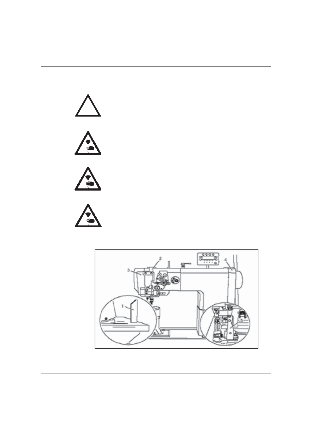
Safety
1-2
1m
A working area of 1 meter is to be kept free both in front of and behind
the machine in operation so that the machine is always easily
accessible.
Never reach into the sewing area while sewing! Danger of injury by
the needle!
Never leave objects on the table while adjusting the machine settings!
Objects can become trapped or be slung away! Danger of injury!
1
Do not operate the machine without support 1! Danger due to top-
heavy sewing head! Machine can tip over backwords when tilted!
1.03 Danger
11-4