JTS UB-900B User manual

Bedienungsanleitung
Instruction Manual
Mode d’emploi
Manual de instrucciones
®
Vertrieb von JTS-Produkten — Distribution of JTS products
UB-900B
Antennenverstärker
Antenna Amplifier
Amplificateur d’antenne
Amplificador de antena


3
DEUTSCH
Bevor Sie einschalten …
Wir wünschen Ihnen viel Spaß mit Ihrem neuen Gerät
von JTS. Bitte lesen Sie diese Bedienungsanleitung
vor dem Betrieb gründlich durch. Nur so lernen Sie alle
Funktionsmöglichkeiten kennen, vermeiden Fehlbe-
dienungen und schützen sich und Ihr Gerät vor even-
tuellen Schäden durch unsachgemäßen Gebrauch.
Heben Sie die Anleitung für ein späteres Nachlesen
auf.
Before switching on …
We wish you much pleasure with your new JTS unit.
Please read these operating instructions carefully prior
to operating the unit. Thus, you will get to know all func-
tions of the unit, operating errors will be prevented,
and yourself and the unit will be protected against any
damage caused by improper use. Please keep the
operating instructions for later use.
ENGLISH
Avant toute installation …
Nous vous souhaitons beaucoup de plaisir à utiliser
cet appareil JTS. Lisez ce mode dʼemploi entièrement
avant toute utilisation. Uniquement ainsi, vous pourrez
apprendre lʼensemble des possibilités de fonctionne-
ment de lʼappareil, éviter toute manipulation erronée et
vous protéger, ainsi que lʼappareil, de dommages
éventuels engendrés par une utilisation inadaptée.
Conservez la notice pour pouvoir vous y reporter
ultérieurement.
FRANÇAIS
Antes de cualquier instalación ...
Le deseamos una buena utilización para su nuevo
aparato de JTS. Por favor, lea estas instrucciones de
uso atentamente antes de hacer funcionar el aparato.
De esta manera conocerá todas las funciones de la
unidad, se prevendrán errores de operación, usted y
el aparato estarán protegidos en contra de todo daño
causado por un uso inadecuado. Por favor, guarde las
instrucciones para una futura utilización.
ESPAÑOL

4
1 Einsatzmöglichkeiten
Der UB-900B ist ein Antennenverstärker für die
Multifrequenz-Empfänger UF-…, US-… und IN-… im
UHF-Bereich 470 – 870 MHz, die mit BNC-Antennen-
buchsen ausgestattet sind. Der Antennenverstärker
dient zur Verbesserung der Störsicherheit und zur
Erhöhung der Übertragungsreichweite. Je nach örtli-
chen Gegebenheiten kann eine doppelte bis dreifache
Reichweite erreicht werden.
Pro Empfänger werden zwei Antennenverstärker
benötigt. Diese können entweder direkt an den Emp-
fänger angeschlossen werden oder über den Anten-
nenverteiler UA-948. Der Verstärker erhält seine
Stromversorgung vom Empfänger oder vom Verteiler
über die Buchse OUTPUT (2).
2 Wichtige Hinweise für den Gebrauch
Das Gerät entspricht allen relevanten Richtlinien der
EU und ist deshalb mit gekennzeichnet.
GDas Gerät ist nur zur Verwendung im Innenbereich
geeignet. Schützen Sie es vor Tropf- und Spritzwas-
ser, hoher Luftfeuchtigkeit und Hitze (zulässiger Ein-
satztemperaturbereich 0 – 40 °C).
GVerwenden Sie für die Reinigung nur ein trockenes,
weiches Tuch, niemals Chemikalien oder Wasser.
GWird das Gerät zweckentfremdet, nicht richtig mon-
tiert oder falsch angeschlossen, kann keine Haftung
für daraus resultierende Sach- oder Personenschä-
den und keine Garantie für das Gerät übernommen
werden.
3 Inbetriebnahme
Für den mobilen Einsatz lässt sich der Antennenver-
stärker auf jedes Mikrofonstativ mit 16-mm-Gewinde
(5/8″) montieren. Für eine Festinstallation liegt ein
Montagewinkel bei, der auch an ein Geräterack
(482 mm/19″) festgeschraubt werden kann.
1) Bei einer Festinstallation sollte zuvor ein Probebe-
trieb erfolgen, damit die optimale Montagestelle für
die Antennen ermittelt werden kann (siehe folgende
Bedienschritte). Danach den beiliegenden Monta-
gewinkel (5) an geeigneter Stelle montieren. Der
Abstand zum zweiten benötigten Antennenverstär-
ker sollte mindestens 0,5 bis 1 m betragen. Der
minimale Abstand hängt von den örtlichen Emp-
fangsbedingungen ab.
Den Antennenverstärker über seine Gewinde-
buchse (3) mit der Montageschraube (6) an den
Montagewinkel festschrauben.
2) Die Antenne des Empfängers auf die Buchse ANT
(4) stecken und nach oben abwinkeln.
3) Die Buchse OUTPUT (2) über ein 50-Ω-Koaxial-
kabel mit BNC-Steckern an einen Antennenein-
gang des Empfängers bzw. des Antennenverteilers
UA-948 anschließen.
4) Den Empfänger bzw. den Antennenverteiler ein-
schalten. Bei korrektem Anschluss leuchtet die rote
Betriebsanzeige (1) auf.
4 Technische Daten
Frequenzbereich: . . . . . 470 – 870 MHz
Verstärkung: . . . . . . . . . 10 dB
Stromversorgung: . . . . . 12 – 18 Vüber Empfänger
oder Antennenverteiler
Einsatztemperatur: . . . . 0 – 40 °C
Abmessungen, Gewicht: 77 × 18 × 76 mm, 140 g
Anschlüsse:. . . . . . . . . . 2 × BNC
Änderungen vorbehalten.
Soll das Gerät endgültig aus dem Betrieb
genommen werden, übergeben Sie es zur
umweltgerechten Entsorgung einem örtli-
chen Recyclingbetrieb.
DEUTSCH
ANT
OUTPUT
1234 56
1Betriebsanzeige
2BNC-Buchse OUTPUT zum Weiter-
leiten des verstärkten Antennensi-
gnals an den Empfänger
316-mm-Gewindebuchse (5/8″) zum
Anschrauben des Montagewinkels
(5) oder eines Mikrofonstativs
4BNC-Buchse ANT zum Aufstecken
der Antenne
5Montagewinkel
6Montageschraube zum Festschrau-
ben des Antennenverstärkers
Diese Bedienungsanleitung ist urheberrechtlich für MONACOR ®INTERNATIONAL GmbH & Co. KG geschützt.
Eine Reproduktion für eigene kommerzielle Zwecke – auch auszugsweise – ist untersagt.

5
ENGLISH
®
1 Applications
The UB-900B is an antenna amplifier for the multi-
frequency receivers UF-…, US-… and IN-… in the
UHF range of 470 – 870 MHz which are equipped with
BNC antenna jacks. The antenna amplifier serves to
improve the interference safety and to enlarge the
transmission range. Depending on the local condi-
tions, it is possible to double or triple the range.
Two antenna amplifiers are required for one receiv-
er. These may either directly be connected to the
receiver or via the antenna splitter UA-948. The ampli-
fier receives its power from the receiver or from the
splitter via the jack OUTPUT (2).
2 Important Notes
The unit corresponds to all relevant directives of the
EU and is therefore marked with .
GThe unit is suitable for indoor use only. Protect it
against dripping water and splash water, high air
humidity, and heat (admissible ambient temperature
range 0 – 40 °C).
GFor cleaning only use a dry, soft cloth, by no means
chemicals or water.
GNo guarantee claims for the unit and no liability for
any resulting personal damage or material damage
will be accepted if the unit is used for other purposes
than originally intended, if it is not correctly mounted
or connected, or not repaired in an expert way.
3 Setting into Operation
For mobile applications the antenna amplifier can be
mounted on any microphone stand with 16 mm (5/8″)
thread. For a fixed installation a mounting bracket is
supplied which can also be screwed to a rack for units
(482 mm/19″).
1) For a fixed installation a trial run should be made
beforehand so that the optimum mounting place for
the antennas can be determined (see the following
operating steps). Then mount the supplied mount-
ing bracket (5) at a suitable place. The minimum
distance to the second required antenna amplifier
should be 0.5 to 1 m. The minimum distance de-
pends on the local conditions of reception.
Screw the antenna amplifier via its threaded jack
(3) with the mounting screw (6) to the mounting
bracket.
2) Connect the antenna of the receiver to the jack ANT
(4) and place it vertically upwards.
3) Connect the jack OUTPUT (2) via a 50 Ω coaxial
cable with BNC plugs to an antenna input of the
receiver or the antenna splitter UA-948.
4) Switch on the receiver or the antenna splitter. With
correct connection, the red power LED (1) lights up.
4 Specification
Frequency range: . . . . . 470 – 870 MHz
Amplification:. . . . . . . . . 10 dB
Power supply: . . . . . . . . 12 – 18 Vvia receiver or
antenna splitter
Ambient temperature: . . 0 – 40 °C
Dimensions, weight: . . . 77 × 18 × 76 mm, 140 g
Connections:. . . . . . . . . 2 × BNC
Subject to technical modification.
If the unit is to be put out of operation defini-
tively, take it to a local recycling plant for a
disposal which is not harmful to the environ-
ment.
All rights reserved by MONACOR ®INTERNATIONAL GmbH & Co. KG. No part of this instruction manual may
be reproduced in any form or by any means for any commercial use.
ANT
OUTPUT
1234 56
1Power LED
2BNC jack OUTPUT for passing on
the amplified antenna signal to the
receiver
316 mm (5/8″) thread jack for screw-
ing the mounting bracket (5) or a
microphone stand
4BNC jack ANT for inserting the
antenna
5Mounting bracket
6Mounting screw for fastening the
antenna amplifier

6
FRANÇAIS
1 Possibilités dʼutilisation
Le UB-900B est un amplificateur dʼantenne pour les
récepteurs multifréquences UF-…, US-… et IN-…
dans la plage UHF 470 – 870 MHz, équipés de prises
dʼantenne BNC. Lʼamplificateur dʼantenne permet
dʼaméliorer la sécurité face aux interférences et à
augmenter la portée de transmission. Selon la con-
figuration des lieux, la portée peut être doublée ou
triplée.
Deux amplificateurs dʼantenne sont nécessaires
par récepteur. Ils peuvent être reliés soit directement
au récepteur soit via le répartiteur dʼantenne UA-948.
Lʼamplificateur reçoit son alimentation du récepteur ou
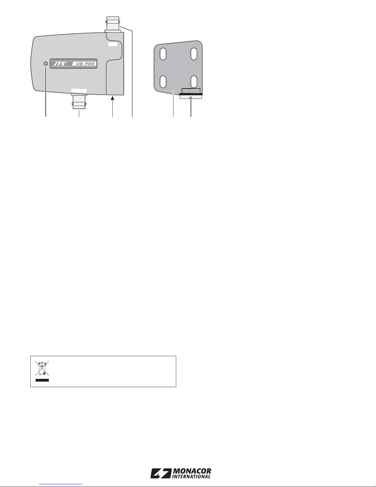
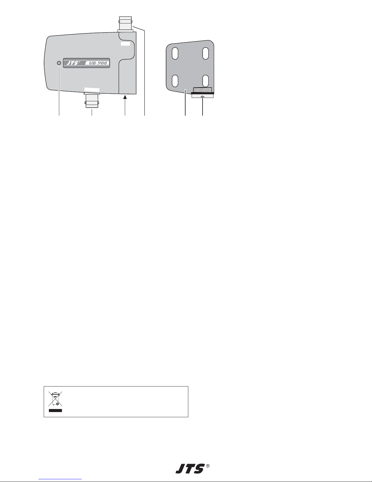
du répartiteur via la prise OUTPUT (2).
2 Conseils dʼutilisation importants
Lʼappareil répond à toutes les directives importantes
de lʼUnion européenne et porte donc le symbole .
GCet appareil nʼest conçu que pour une utilisation en
intérieur. Protégez-le de tout type de projections
dʼeau, des éclaboussures, dʼune humidité élevée et
la chaleur (plage de température de fonctionnement
autorisée : 0 – 40 °C).
GPour le nettoyer, utilisez uniquement un chiffon sec
et doux, en aucun cas, de produits chimiques ou
dʼeau.
GNous déclinons toute responsabilité en cas de dom-
mages matériels ou corporels résultants si lʼappareil
est utilisé dans un but autre que celui pour lequel il a
été conçu, sʼil nʼest pas correctement monté ou
branché, en outre, la garantie deviendrait caduque.
3 Fonctionnement
Pour une utilisation mobile, lʼamplificateur dʼantenne
peut être monté sur un pied de micro avec filetage
16 mm (5/8″). Pour une installation fixe, un étrier de
montage est livré, il peut également être vissé à un
rack (482 mm/19″).
1) Pour une installation fixe, il convient dʼeffectuer un
test pour pouvoir déterminer le lieu de montage
optimal des antennes (voir points suivants).
Ensuite, montez lʼétrier de montage livré (5) à un
endroit adéquat. La distance minimale avec le
second amplificateur dʼantenne nécessaire devrait
être de 0,5 à 1 m. La distance minimale dépend des
conditions de réception.
Vissez lʼ amplificateur dʼantenne via sa prise file-
tée (3) avec la vis de montage (6) sur lʼétrier.
2) Mettez lʼ antenne du récepteur dans la prise ANT (4)
et orientez-la verticalement vers le haut.
3) Reliez la prise OUTPUT (2) via un câble coaxial
50 Ω avec fiches BNC mâles à une entrée dʼan-
tenne du récepteur ou du répartiteur dʼantenne
UA-948.
4) Allumez le récepteur ou le répartiteur dʼantenne. Si
le branchement est correct, le témoin de fonction-
nement rouge (1) brille.
4 Caractéristiques techniques
Plage de fréquence: . . . 470 – 870 MHz
Amplification : . . . . . . . . 10 dB
Alimentation : . . . . . . . . 12 – 18 Vpar récepteur ou
répartiteur dʼantenne
Température de
fonctionnement : . . . . . . 0 – 40 °C
Dimensions, poids :. . . . 77 × 18 × 76 mm, 140 g
Branchements :. . . . . . . 2 × BNC
Tout droit de modification réservé.
Lorsque lʼappareil est définitivement retiré du
service, vous devez le déposer dans une
usine de recyclage adaptée pour contribuer à
son élimination non polluante.
Notice dʼutilisation protégée par le copyright de MONACOR ®INTERNATIONAL GmbH & Co. KG. Toute repro-
duction même partielle à des fins commerciales est interdite.
ANT
OUTPUT
1234 56
1Témoin de fonctionnement
2Prise BNC OUTPUT pour diriger le
signal dʼantenne amplifié sur le
récepteur
3Prise filetée 16 mm (5/8″) pour vis-
ser lʼétrier de montage (5) ou un
pied micro
4Prise BNC ANT pour placer lʼan-
tenne
5Etrier de montage
6Vis de montage pour visser lʼamplifi-
cateur dʼantenne

7
ESPAÑOL
®
1 Aplicaciones
El UB-900B es un amplificador de antena para los
receptores multifrecuencias UF-…, US-… e IN-… en
el rango UHF de 470 – 870 MHz que están equipados
con jacks de antena BNC. El amplificador de antena
sirve para mejorar la seguridad de interferencia y para
ampliar la distancia de transmisión. Dependiendo de
las condiciones locales, es posible doblar o triplicar la
distancia.
Se necesitan dos amplificadores de antena para un
receptor. Estos pueden estar, o directamente conecta-
dos al receptor, o mediante el repartidor de antena
UA-948. El amplificador recibe su alimentación del re-
ceptor o del repartidor mediante el jack OUTPUT (2).
2 Notas importantes
La unidad corresponde a todas las directivas relevan-
tes de la UE y por ello está marcada con .
GLa unidad sólo está indicada para un uso en interior.
Protéjala de goteos y salpicaduras de agua, hume-
dad elevada del aire, y calor (gama de temperatura
ambiente admisible: 0 – 40 °C).
GPara limpiar utilice sólo un paño seco y suave, no
utilice productos químicos o agua.
GNo se aceptará ninguna reclamación para la unidad
ni se aceptará ninguna responsabilidad en caso de
daños personales o patrimoniales causados si la
unidad se usa para otros fines distintos a los origi-
nalmente concebidos, si no se monta o se conecta
correctamente.
3 Puesta en marcha
Para aplicaciones móviles, se puede montar el ampli-
ficador de antena en cualquier pie de micrófono
con rosca de 16 mm (5/8″). Para una instalación fija se
entrega un soporte de montaje que también se puede
atornillar a un rack para unidades (482 mm/19″).
1) Para instalación fija se recomienda hacer una
prueba antes, de modo que se pueda determinar el
lugar de montaje óptimo para las antenas (vea los
pasos operativos siguientes). Luego monte el
soporte de montaje entregado (5) en un lugar indi-
cado. La distancia mínima con el segundo amplifi-
cador de antena requerido debería ser de 0,5 a 1 m.
La distancia mínima depende de las condiciones
locales de recepción.
Atornille el amplificador de antena mediante su
jack de rosca (3) con el tornillo de montaje (6) al
soporte de montaje.
2) Conecte la antena del receptor al jack ANT (4) y
colóquela verticalmente hacia arriba.
3) Conecte el jack OUTPUT (2) mediante un cable
coaxial de 50 Ω con tomas BNC a una entrada
de antena del receptor o del repartidor de antena
UA-948.
4) Encienda el receptor o el repartidor de antena. Con
la conexión correcta se enciende el LED rojo de
encendido (1).
4 Características técnicas
Rango de frecuencias: . 470 – 870 MHz
Amplificación: . . . . . . . . 10 dB
Alimentación: . . . . . . . . 12 – 18 Vmediante recep-
tor o repartidor de antena
Temperatura ambiente:. 0 – 40 °C
Dimensiones, peso: . . . 77 × 18 × 76 mm, 140 g
Conexiones: . . . . . . . . . 2 × BNC
Sujeto a modificaciones técnicas.
Si la unidad debe ser retirada del funciona-
miento definitivamente, llévela a un centro de
reciclaje local para su disposición no conta-
minante para el medio ambiente.
ANT
OUTPUT
1234 56
1LED de encendido
2Jack BNC OUTPUT para pasar la
señal de antena amplificada al re-
ceptor
3Jack de rosca 16 mm (5/8″) para
atornillar el soporte de montaje (5) o
un pie de micrófono
4Jack BNC ANT para insertar la an-
tena
5Soporte de montaje
6Tornillo de montaje para sujetar el
amplificador de antena
Manual de instrucciones protegido por el copyright de MONACOR ®INTERNATIONAL GmbH & Co. KG.
Toda reproducción mismo parcial con fines comerciales está prohibida.

www.jts-germany.de
MONACOR INTERNATIONAL GmbH & Co. KG, Zum Falsch 36, 28307 Bremen, Germany
Copyright by MONACOR INTERNATIONAL. All rights reserved. A-1521.99.01.02.2014
©
Table of contents
Languages:
Other JTS Amplifier manuals
Popular Amplifier manuals by other brands

Peavey
Peavey IPA 150 Specifications

Harman Kardon
Harman Kardon SIGNATURE 2.1 owner's manual

Simaudio
Simaudio MOON Evolution W-8 owner's manual

Kenwood
Kenwood M-A300 instruction manual

YORKVILLE
YORKVILLE Bassmaster YBA200 Service manual

Balanced Audio Technology
Balanced Audio Technology VK-150SE owner's manual