Kairak KU044SC User manual

Undercounter Refrigerators and Freezers
PAGE 1
INSTRUCTION MANUAL
KU SERIES FULL-SIZE UNDERCOUNTER REFRIGERATORS
KU044SC, KU072SC & KU100SC
SALES KAIRAK. 1158 N. Gilbert St., Anaheim, CA 92801, Phone: (714) 870-8661, Web: www.kairak.com
MNFG KAIRAK. 4401 Blue Mound Road, FT. Worth, TX 76106
© KAIRAK, a division of ITW Food Equipment Group LLC. All Rights Reserved.

-Locating the Equipment
-Packaging
-Adjusting the Casters
-Cord and Plug
-Power Supply
-Refridgerators
-Freezers
-Cleaning the Condenser/Filter
-Replacing the Gaskets
-Cleaning the Cabinet Surface
-Door Re-hinging
-Removing the Door and Installing Ref Drawers
-Control Features
-Alarm Explanations
-Control Panel Diagram
D- Notes to User
Enter The Service Access
Service Parameters
Adjusting Thermostat Set Point High
Adjusting Thermostat Set Point Low
Changing The Temperature Scale
Setting The 24-Hour Clock
Setting The Date
Setting Daylight Savings Time
Starting A Manual Defrost
Setting Defrost Lockouts
Adjusting The Drawer Perimeter Heaters
Adjusting The Room Temperature Offset
Setting The Audible Alarm Style
Viewing Sensor Temperatures

The serial tag is a permanently affixed label on which is recorded vital electrical and
refrigeration data about your Kairak product, as well as the model and serial number.
This tag is located inside the lower storage cabinet on the right hand wall on all standard
KRP models. Prior to installation, test the electrical service to assure that it agrees with
the specifications of the equipment marked on the serial tag.
The permanent ID# of your Kairak unit
The model # of your Kairak unit
Voltage
Cycle
Phase
Maximum amp draw
Minimum circuit ampacity
Light wattage
Heater amperage (Hot Food units only)
Refrigerant type used
High & low side operating pressures and refrigerant charge
Designates agency listings

All Kairak products are factory tested for performance and are free from defects when
shipped. The utmost care has been taken in crating this product to protect against damage
in transit.
You should carefully inspect your Kairak unit for damage during delivery. If damage is
detected, you should save all the crating materials and make note on the carrier’s Bill Of
Lading describing the damage. A freight claim should be filed immediately. If damage
is subsequently noted during or immediately after installation, contact the respective
carrier and file a freight claim. There is a fifteen (15) day limit to file freight damage with
the carrier. Under no condition may a damaged unit be returned to Kairak without first
obtaining written permission (return authorization). You may contact Kairak customer care
at (714) 870-8661 to request a return.
Select a proper location for your unit, away from extreme heat or cold. Allow enough
clearance between the unit and the side wall in order to make use of the door stay open
feature at 1200 (self-closing feature operates up to 900). The door(s) must be able to
open a minimum of 900 in order to make use of the maximum clear door width.
Your Kairak unit is shipped from the factory bolted to a sturdy wooden pallet in stretch
wrapped material.
Most exterior stainless steel surfaces have a protective vinyl covering to prevent scratching
during manufacturing, shipping and installation. After the unit is installed in place of
application peel, remove and discard the covering from all surfaces.
To remove the wooden pallet, first if at all possible, we suggest that the cabinet remain
bolted to the pallet during all transportation to the point of final installation. The bolts
can then be removed with a 1/2” socket wrench. Avoid laying the unit on its front, side
or back for removal of the pallet.
NOTE: Kairak does not recommend laying the unit on its front, side or back. If
you must, please allow the unit to remain in an upright position for 24 hours
before plugging it in so that the compressor oils and refrigerant may settle.

To install legs or casters, slide leg or caster into the caster channel from the side of the
unit without the refrigeration system.
To adjust the legs or casters, loosen the two bolts and move leg or caster to desired
location, spacing between leg or caster not to exceed 48 inches. Leg or caster on each
end of the unit can not exceed 8 inches from the end of the cabinet (Figure 1).
NOTE: Kairak recommends to position legs or casters under the mullion when
possible.
All self-contained models are shipped standard with a NEMA 5-15P plug and 9 foot cord.
Select only a dedicated electrical outlet for power source.
NOTE: Do not under any circumstances, cut or remove the round grounding
prong from the plug, or use an extension cord.
The supply voltage should be checked prior to connection to be certain that proper
voltage for the cabinet wiring is available (refer to the serial tag to determine correct unit
voltage, see page 1). Make connections in accordance with local electrical codes. Use
qualified electricians.
Use of a separate, dedicated circuit is required. Size wiring to handle indicated load and
provide necessary overcurrent protector in circuit (see amperage requirements on the
unit’s serial tag).

Both refrigerators and Freezers do not require manual defrosting. During normal
operation, a refrigerator continuously circulates above freezing cabinet air through the
coil. A compressor “OFF” cycle occurs every 2 1/2 Hours for 20 minutes to melt any
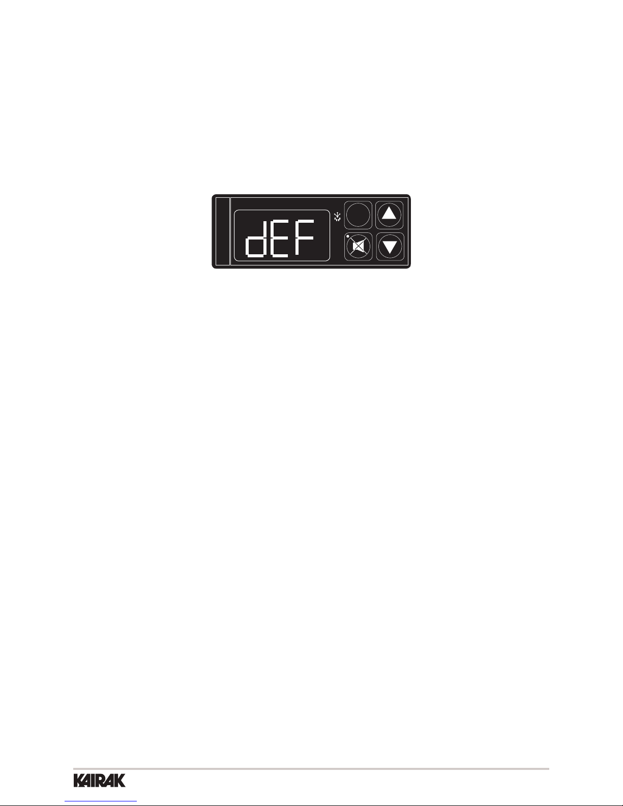
frost which may accumulate on the coil during the compressor “ON” cycle. The control
will read “dEF” and the green water drop will be illuminated (Figure 2). With standard
holding refrigerators, high relative humidity is also maintained to prevent dehydration of
stored product.
FREEZER
SET
INTELA-TRAUL
°F °C
During normal operation, a freezer continuously circulates below freezing cabinet air
through the coil. The coil requires a periodic defrosting for proper operation. This is
accomplished by an automatic, time activated, temperature/time terminated, defrost
program, utilizing hot gas from the refrigeration system. The controller is preset at the
factory for six equally spaced defrost cycles within each 24-hour period.
At the start of a freezer defrost cycle, the compressor, condenser fan and evaporator fan
shut off. The hot gas relay will be energized, this will energize the hot gas solenoid valve
thru the normally open contacts and the condenser fan circuit will be de-energized thru
the (normally closed contacts), and the compressor will restart. When the evaporator
coil sensor reaches 400 F the coil is fully defrosted or if the maximum time of defrost
duration (20 minutes) is reached (which ever comes first) then the defrost hot gas relay
is de-energized. The condenser fan restarts and the hot gas solenoid valve closes, The
compressor system returns to the cooling mode. Total refrigeration system operation
is then resumed (green snowflake icon goes out) and the display will show def for
an additional 10 minutes then return to reading the inside cabinet temperature. The
evaporator fan(s) are delayed from starting at the termination of the defrost cycle and will
automatically resume by time or temp delay (5 minutes or 300 F coil sensor temperature,
whichever comes first ).
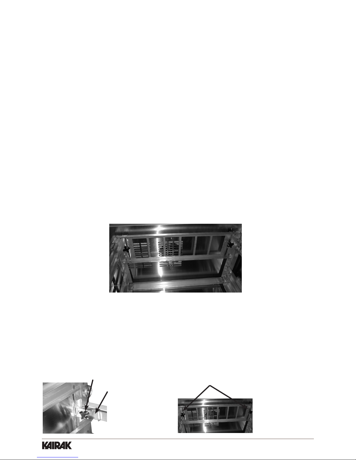
During freezer defrost operation, heat is confined to the coil enclosure to prevent any
significant rise in temperature within the food zone. The fan delay control function upon
termination of a defrost cycle is two-fold. First, to prevent blowing warm air into the food
storage area. Second, to prevent any condensation on the defrost coil from being blown
into the food storage area.
The microprocessor control is set from the factory to terminated defrost at 20 minutes
in the event of sensor failure. This setting should never be tampered with, without first
consulting Kairak’s Technical Service department.

The most important thing you can do to insure a long, reliable service life for your Kairak
is to regularly clean the condenser coil and or filter if provided.
The microprocessor control will notify you through a “CLN-FIL” message when the
condensing temperature of the refrigerator reaches 140 degrees F or greater. If the
condensing temperature reaches 160 degrees F the compressor will automatically turn
off . When the temperature drops below 140 degrees F the compressor will restart and
when the temperature drops below 120 degrees F the alarm will reset.
To clean the condenser/filter, first disconnect electrical power to the cabinet and remove
the front louver assembly. To do so, place hands under the louver panel and pull out and
up to get louver panel off bracket of the unit (Figure 3).
Proceed to vacuum or brush any dirt, lint or dust from the finned condenser coil/filter, the
compressor and other cooling system parts. If significant dirt is clogging the condenser
fins or filter, use compressed air to blow this clear. To replace the louver assembly reverse
the process.

To remove the gasket to be replaced, grasp it firmly by one corner and pull it out. Before
attempting to install a new gasket, both the unit and the gasket itself must be at room
temperature. Insert the four corners first by using a rubber mallet (or hammer with a block
of wood). After the corners are properly inserted, work your way towards the center from
both ends by gently hitting with a mallet until the gasket is completely seated in place
(see figure below for proper gasket placement).
Exterior stainless steel should be cleaned with warm water, mild soap and a soft cloth.
Apply with a dampened cloth and wipe in the direction of the metal grain.
Avoid the use of strong detergents and gritty, abrasive cleaners as they may tend to mar
and scratch the surface. Do NOT use cleansers containing chlorine, such as bleach, this
may promote corrosion of the stainless steel.
Care should also be taken to avoid splashing the unit with water, containing chlorinated
cleansers, when mopping the floor around the unit.
For stubborn odor or spills, use baking soda and water (mixed to a 1 tbsp baking soda
to 1 pint water ratio).
A stainless steel polish is recommended for shining of unit.

Your Kairak full-size undercounter model door(s) are field re-hingeable. If re-hinging
is required, please contact our in-house service department at 800-833-1106 for
instruction.
Doors are supplied standard on all TU Series Full-Size Undercounter models. However,
we have engineered our refrigerator models (only) with a drop-in feature that allows you
to easily convert door(s) into two 6” deep drawers or three 4” deep drawers.
The door(s) on the refrigerator models (only) can easily be converted to drawers in the
field. To begin the process, open the door to its maximum position. Support the non-
hinged end of the door so minimum movement occurs. When the bolts from the lower
hinge plate are removed, remove the lower hinge plate and then the door from the top
hinge bracket plate and then the door from the top hinge bracket. The hinge plate pin
and plastic bushing will remain in the top hinge plate.
Once the door(s) have been removed, Insert drawer frame as shown below (Figure 5).
Once the drawer frame has been inserted, the drawer frame module can be installed by
tighting the black front and back clamping knobs (2 of each) located on the cross rail
locks and liner locks. Slide the front cross rail locks towards the center of the drawer
frame module and allow the liner locks to drop down from the top of the liner. Insert the
door frame module push towards the back of the unit. The entire frame assembly is now
installed and ready for use.

Your new refrigerator or freezer cabinet is equipped with a state-of-the-art microprocessor
control, which precisely regulates operation and provides alarms when problems occur.
It is supplied from the factory completely ready for use and requires no adjustments, but
without the audible alarms activated. See pages 10 thru 16 for more information.
FREEZER
SET
INTELA-TRAUL
°F °C
•Eliminatesexternaldefrosttimeclock.
•Defrostcyclecanbequicklyadjustedtosuitindividuallocationanduse.
•Mustbesetatpower-up.(Seepage11,“Settingthe24-HourClock”)
•WillautomaticallyupdateforDaylightSavingsTime.
The face of the control is water resistant to provide for protection during cleaning.
See “Customer / Service Parameters” on Page 9.
- See “Setting Defrost Lockouts” on page 14.
Customers can set up to 4 different defrost lockout periods. The lockout prevents the unit
from going into a defrost cycle during peak kitchen use. Note: The 24-hour clock must
be set for this feature to operate correctly.
The “No-Sweat” feature is an energy savings system that allows the customer to adjust the
percent of time for the door/drawer heater to be “On” as needed for the prevailing ambient
conditions (from 0 - 100% of the time each day). It is used to prevent condensation from
forming around the perimeter of the drawers. The factory default setting is 100%. Adjust
this set point down to a point just before condensation forms to save energy.

(See the following pages for explanations)
•HighCabinetAirTemperature
•LowCabinetAirTemperature
•LossOfPower
•SensorFailure
•CleanCondenser
•3-DigitLEDDisplay
•DefrostinProgressIcon
•FahrenheitorCelsiusTemperatureScaleInUse
NOTE: Explanation of alarms assume the audible alarm style is set at a 3-second burst or
a continuous audible alarm. References to the audible alarm do not apply if the audible
alarm style is set to OFF (Refer to page 16 for setting the audible alarm style).
The audible alarm will sound
and the display will read HI CAb when the temperature inside
the cabinet rises above a pre-programmed limit. The limit is
determined by the type of unit being operated (i.e.: refrigerator/
freezer). To turn off the audible alarm, press the alarm cancel
button. The visual alarm text will continue to display until the
cabinet air temperature falls below the limit. If the temperature
does not fall below the limit within 5 minutes, the audible alarm*
will sound again and an additional Call Service message will
display.
•Doorsopenforextendedperiodsoftime
•Largeamountsofhotproductplaced
inside the cabinet
•Condensercoildirty
•CoolingCompressorFailure.CallService
•RefrigerationProblems

The audible alarm will sound and
the display will read Lo Cab when the temperature inside the cabinet
falls below a pre-programmed limit. The limit is determined by the
type of unit being operated (i.e.: refrigerator/ freezer). To turn off the
audible alarm, press the alarm cancel button. The visual alarm text
will continue to display until the cabinet air temperature rises above
the limit. If the temperature does not rise above the limit within 5
minutes, the audible alarm will sound again and an additional Call
Service message will display.
•Noproductinunit
•Failedsensors
•StuckEvaporatorRelay
: The audible alarm will sound and the display will
read ELE LOS, when the unit regains power after an outage. To turn
off the audible alarm and/or clear the visual text, press the alarm
cancel button.
: The audible alarm will sound and the display
will read “Clean Filter” when discharge temperatures exceeds 140
degrees. As the load on the condenser decreases, the alarm will turn
off by itself. As the temperature on the condenser continue to rise,
the audible alarm will return until the problem has been eliminated.
The audible alarm will sound and the display will
read CAB SEN, COL SEN or DIS SEN when that particular sensor
has failed to operate. To turn off the audible alarm, press the alarm
cancel function of the sensor, the audible alarm will sound again in
either 5 minutes or 24 hours.

You only have 20-30 seconds between button pushes. If you take longer than 30 seconds,
the controller will revert back to displaying the cabinet temperature. If you enter the wrong
security code, the controller will revert back to displaying the cabinet temperature. You
can exit the parameters at any time by pressing the alarm cancel button or by waiting
20-30 seconds.
FREEZER
SET
INTELA-TRAUL
°F °C

Use the security code 0, A, 1 and the following instructions:
Press the set button . The display will read Service Access.
Press the set button .
The display will show three zeros with the left zero flashing
Press the set button .
The display will show three zeros with the center zero flashing
Press the down arrow key to sequence through F, E, d, C, b, A, 9, 8, 7,…etc.
When you reach A press set .
The display will show zero, A, zero with the right zero flashing
Press the up arrow key to sequence through 1, 2, 3, 4, 5, 6, 7, 8, 9, A, b,…etc.
When you reach 1 press set .
The display will read Thermostat Set Point High. Press to view
and again to exit.
You are now in the SERVICE PARAMETERS.
SET
SET
SET
SET
SET
SET
SET

Listed below are the available parameters in the order they appear, using the down arrow
key on the controller. You can use either the up or down arrow keys to scroll through the
options.
Defrost Lockout 3
Defrost Lockout 4
Dew Point
Compensation Factor
Room Temperature Offset
Audible Alarm Style
Cabinet Air Sensor Temp
Evaporator Coil SensorTemp
Discharge Line Sensor Temp
Thermostat Set Point High
Thermostat Set Point Low
Temperature Scale
Time (24-hour clock)
Date (month-day-year)
Daylight Savings
Start Manual Defrost
Defrost Lockout 1
Defrost Lockout 2

This parameter sets the high point of the desired cabinet temperature range. Typically,
freezers will range from -3° F to 0° F (-19° C to –18° C) and refrigerators will range from
36° F to 40° F (2° C to 4° C) for this parameter setting. This parameter is preset at the
factory and does not have to be adjusted unless the customer chooses to do so. Note:
Set Point Low and Set Point High cannot be set to the same temperature. There must be
at least 1-2 degree difference between the two settings.
Follow the instructions to enter the customer access code on page 8. When the control
display reads Thermostat Set Point High. Press the set button .
Use the arrow keys to adjust the temperature to your desired setting.
When the display shows the temperature you want press the set button .
The display will then read Thermostat Set Point High.
You can use the up or down arrow keys to scroll to the next parameter .
or press the alarm cancel button to exit .
S E T
)
))
S E T
This parameter sets the low point of the desired cabinet temperature range. Typically,
freezers will range from –6° F to -4° F (-21° C to –20° C) and refrigerators will range from
32° F to 34° F ( 0° C to 1° C) for this parameter setting. This parameter is preset at the
factory and does not have to be adjusted unless the customer chooses to do so. Note:
Set Point Low and Set Point High cannot be set to the same temperature. There will be
at least 1-2 degree difference between the two settings.
Follow the instructions to enter the service access code on page 8. When the control
displays Thermostat Set High, press the down arrow key until the control
display reads Thermostat Set Point Low. Press the set button .
Use the arrow keys to adjust the temperature to your desired setting.
When the display shows the temperature you want press the set button .
The display will then read Thermostat Set Point Low.
You can use the up or down arrow keys to scroll to the next parameter .
or press the alarm cancel button to exit .
S E T
)
))
S E T

The temperature scale determines if the temperature displayed will be in degrees
Fahrenheit or degrees Celsius.
Follow the instructions to enter the customer access code on page 8. When the control
displays Thermostat Set High, press the down arrow key until the control
display reads Temperature Scale. Press the set button .
The display will start with the current setting either for degrees Fahrenheit
or for degrees Celsius.
Use the arrow keys to toggle between the options.
When the display shows the scale you want press the set button .
The display will then read Temperature Scale.
You can use the up or down arrow keys to scroll to the next parameter
or press the alarm cancel button to exit .
S E T
)
))
S E T

Follow the instructions to enter the customer access code on page 8. When the control
displays Thermostat Set High, press the down arrow key until the control
display reads Clock. Press the set button .
The display will show Hours. The right two numbers will be flashing.
Use the arrow keys to set the hour.
When the correct hour is displayed, press the set button .
The display will show Minutes. The right two numbers will be flashing.
Use the arrow keys to set the minutes .
When the correct minutes are displayed, press the set button .
The display will then read Clock.
You can use the up or down arrow keys to scroll to the next parameter
or press the alarm cancel button to exit .
The internal time clock must be set in order for the data storage memory to correctly log
events and to allow any defrost lockout to occur at the correct time of day. If the clock is
not set, the control assumes the time is 12 am at the time power is supplied to the unit.
The hours on a 24-hour time clock read the following way:
SET
SET
)
))
SET
H01 = 1:00 a.m.
H02 = 2:00 a.m.
H03 = 3:00 a.m.
H04 = 4:00 a.m.
H05 = 5:00 a.m.
H06 = 6:00 a.m.
H07 = 7:00 a.m.
H08 = 8:00 a.m.
H09 = 9:00 a.m.
H10 = 10:00 a.m.
H11 = 11:00 a.m.
H12 = 12:00 p.m.
H13 = 1:00 p.m.
H14 = 2:00 p.m.
H15 = 3:00 p.m.
H16 = 4:00 p.m.
H17 = 5:00 p.m.
H18 = 6:00 p.m.
H19 = 7:00 p.m.
H20 = 8:00 p.m.
H21 = 9:00 p.m.
H22 = 10:00 p.m.
H23 = 11:00 p.m
H24 = 12:00 a.m.

The date must be set in order for the data storage memory to correctly log events. Follow
the instructions to enter the service access code on page 8. When the control displays
Thermostat Set Point High, press the down arrow key until the control
display reads Date. Press the set button .
The display will show (year). The right two numbers will be flashing. Press
the arrow keys to set the year. When the correct year is displayed, press the
set button . The display will show (month). The right two numbers
will be flashing. Use the arrow keys to set the month. When the correct
month is displayed, press the set button . The display will show (day).
The right two numbers will be flashing. Press the arrow keys to set the
day. When the correct day is displayed, press the set button . The display will
then read Date. You can use the up or down arrow keys to
scroll to the next parameter. Press the alarm cancel button to exit .
This parameter is preset at the factory to automatically adjust the 24-hour clock for Daylight
Savings Time. Follow the instructions to enter the customer access code on page 8.
When the control displays Thermostat Set Point High, press the down arrow
key until the display reads Daylight Savings Time.
Press the set button . The display will show Daylight Savings Time
(Yes, automatically adjust for Daylight Savings Time). For “YES” press the set button
,for “NO” press the up or down arrow key .
The display will read Daylight Savings Time (no). Press the set button .
The display will read Daylight Savings Time.
You can press the up or down arrow keys to scroll to the next parameter or
press the alarm cancel button to exit .
SET
SET
SET
SET
)
))
SET
SET
)
))

This parameter allows a service technician to start a defrost cycle at any time. This
parameter will override any lockout settings.
Follow the instructions to enter the customer access code on page 8. When the control
displays Thermostat Set High, press the down arrow key until the control
display reads Start Manual Defrost.
Press the set button
The display will show
Press either arrow key
The display will show
Press the set button
NOTE: Kairak refrigerator units also have an off-cycle defrost, at which time the control will
read This defrost is temperature terminated and can last from 3 - 20 minutes
(dEF will be displayed for 20-37 minutes time).
The defrost icon will be lit, and the display will
read when the unit is in defrost.
SET
SET
DEFROSTICON
This manual suits for next models
2
Table of contents
Other Kairak Refrigerator manuals