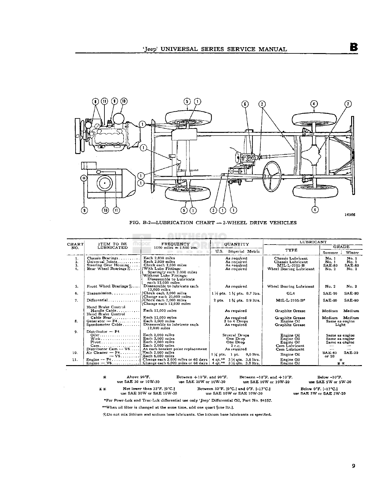
Kaiser-Jeep Jeep CJ-3B User manual

1953-71
SERVICE
MANUAL
JeeP
UNIVERSAL
4-WHEELDRIVE
CJ-3BCJ-5A
CJ-5
CJ-6
CJ-6A
2-WHEELDRIVE
DJ-5
DJ-6
Copyright®
1977
FIJeepCorporation
CorporatePublications
Printed
inUSA
Reprinted
6-77
SM-1046
SECTION
INDEX
NAME
Section
General
Data
A
Lubrication
B
Tune-Up
C
Hurricane
F4Engine
D
DauntlessV-6Engine
Dl
Fuel
System
E
Exhaust
System
F
Exhaust
EmissionControl
SystemF4Engine
Fl
Exhaust
EmissionControl
SystemV6-225Engine
F2
CoolingSystem
G
Electrical
H
Clutch
I
3-Speed
Transmission
J
4-Speed
Transmission
Jl
Transfer
Case
K
PropellerShafts
L
Front
Axle
M
Rear
Axle
N
Steering 0
Brakes
P
Wheels 0
Frame
R
Springs
ShockAbsorbers
S
Body
T
Miscellaneous
U

IMPORTANT
DEALER
INFORMATION
This
manual,SM-1046,coverscurrent'Jeep'UniversalSeriesvehicles,and
pastmodels,
except
as
noted
hereinafter:
SM-1037shouldberetainedinyourservice
library
for
informationrelatedtothe
6-volt
electricalsystem,orthe
singlebrakesystem.
SM-1002-R5
(nolongeravailable)shouldberetained
forinformationrelatedtothe
CJ-2A,CJ-3A
or
DJ-3A
models
equippedwiththeL4-134
engine.
The
above
threemanualsprovide
full
servicecoveragesinceinceptionofthe
'Jeep'Universaland
1
Jeep'Dispatchermodelvehicles.

'Jeep*
UNIVERSAL
SERIESSERVICE
MANUAL
A
GENERAL
DHTfl
Contents
SUBJECT
PAR.
General
A-l
Vehicle
Description.A-2
Vehicle
IdentificationA-3
Identification
NumberLocationA-4
Serial
NumberLocationA-5
Engine
CodeNumberA-6
Plate-And-Trim
OptionPlateA-7
General
SpecificationsA-8
A-1.
GENERAL
This
manualisprovidedfortheguidanceofall
automotiveservicemen,vehicleowners,and
servicesalesmenwho
repair,
maintain,oradjust
the'Jeep'UniversalSeriesvehicles.Theinforma-
tionhereinwaspreparedfromtheserviceman's
viewpointto
give
himtheaccurateandconcise
data
hemayneedtoservicetheentirevehicle.
The
informationisnotelementaryasitisintended
forautomotiveservicemenwhoarefamiliarwith
automotiveconstructionandrepairingeneral.It
isnotintended,norwoulditbepossibleinsuch
limited
space,tocovereverypossiblerepairthat
hemayencounter.Allspecificationsareinaccord
with
EngineeringSpecificationsandshouldbe
adhered
toinallworkonthevehicle.
The
manualsectionsfollowlogicaldivisioninto
major
componentsofthevehicles.Thefirst
page
ofeachsectionhasa detailedindexofthe
contents
ofthatsection.Subjectmattercoversallmodels
included
inthismanualunlessanexceptionfora
particular
modelisspecificallymentioned.
Specificationsandcomponentscoveredwerefor
standard
productionmodelsof'Jeep'vehicles
current
atthetimethemanualwasapprovedfor
printing.
'Jeep'Corporationreservestherightto
discontinuemodelsatanytimeorchangespecifi-
cationsordesignofanyofitsmodelswithout
noticeandwithout
incurring
anyobligation.
A-2.
VehicleDescription
This
manualcoversallstandardproduction'Jeep'
Universal
modelscurrentlybeingproducedatthe
timethismanualwasapprovedforpublication.
Significant
changesmadeineachmodelsinceit
wasfirst producedareincludedinthemanual.
A
descriptionofeachmodelfollows.
General
specificationsforeachmodelarelistedinPar.A-8.
Detailedspecificationscoveringmajorvehicleunits
are
listedattheendofeachsectionofthemanual.
CJ-3B
—
This
isa 4-wheel-drive'Jeep'Universal
model,equippedwiththefour-cylinder
Hurricane
F4-134engine.Wheelbaseis
80".
CJ-5
CJ-5A
— Theseare4-wheel-drive'Jeep'Universal
models,equippedwitheithertheDaunt-
less
V-6engine,orthefour-cylinder
Hurricane
F4-134engine.Wheelbaseis
81".
CJ-6
CJ-6A
— Theseare4-wheel-drive'Jeep'Universal
models,equippedwitheithertheDaunt-
less
V-6engine,orthefour-cylinder
Hurricane
F4-134engine.Wheelbaseis
101".
DJ-5
DJ-6
— Theseare2-wheel-drive'Jeep'Universal
models,equippedwiththefour-cylinder
Hurricane
F4-134engine.DJ-5wheel-
baseis81".DJ-6wheelbaseis101".
A-3.
VehicleIdentification
Each
'Jeep'vehiclemodelserieshasoneormore
serial
numberprefixestoidentifyit.Complete
identificationofa specificvehiclerequiresthe
prefix
plusthe
serial
number.
Serial
numbersare
consecutiveforeachprefixgrouping.Prefixinfor-
mationfollowing
will
identifythe'Jeep'models
shownby
serial
numberprefixfrommodelinception
todate.-.
••
' . -
Note:
Vehicleswitha
serial
numberprefixoffive
(5)ormoredigitsthathaveanS,5,or7 asthelast
digitareequippedwith
Exhaust
Emission
Control.
A
number1 inthesixth(6th)digitwithina seven
(7)digitvehicle
serial
numberprefixindicates
Left
Hand
Drive;
a 2 indicatesRight
Hand
Drive;
a
3 indicates
Left
Hand
Drive
California
Exhaust
Emission
Control
Engine;
a 4 indicatesRight
Hand
Drive
California
Exhaust
Emission
Control
Engine.
3

A
GENERAL
DATA
'Jeep'
Serial
No.
'Jeep'
Serial
No.
Model
Prefix
Model
Prefix
CJ-3B
453-GB2
CJ-3B
454-GB2
57348
8105
8105014
CJ-5
57548
CJ-6
57648
8305 8405
8305A 8405A
8305S 8405S
8305AS 8405AS
8305014 8405014
8305015 8405015
8305016 8405016
8305017 8405017
CJ-5A
8322
CJ-6A
8422
8322A 8422A
8322S 8422S
83
2 2AS
8422AS
.
DJ-5
8505
DJ-6
8605
8505A 8605A
8505S 8605S
8505AS 8605AS
8505014
8505015
8505016
8505017
Any
prefixnotgivenhereforoneofthelisted
modelsindicatesa specialvehiclewhosedifferences
from
standardarenotcoveredinthismanual.
A-4.IDENTIFICATION
NUMBER
LOCATION
All
'Jeep*vehiclesand
some
oftheirmajorcom-
ponentshaveidentifyingnumbers.
Paragraphs
fol-
lowing
will
describethelocationofidentifying
numbers.
A-5.
Vehicle
Serial
Number
The
vehicle
serial
numberisstampedona metal
platelocatedonthedashunderthehood.Itison
theleftsideofthevehicleformodels
CJ-5,CJ-5A,
CJ-6,
CJ-6A,
DJ-5andDJ-6asshowninFig.
A-l.
It
isontherightsideofthevehicleformodel
CJ-3B,
asshownin
Fig.
A-2.RefertoPar.A-3for
specificinformationoncodes.
FIG.
A-l—CJ-5,CJ-5A,CJ-6,CJ-6A,
DJ-5,DJ-6
VEHICLE
SERIAL
NUMBERLOCATION
FIG.
A-2
CJ-3B
VEHICLE
SERIAL
NUMBERLOCATION
A-6.
EngineCodeNumber
The
engineidentificationnumberconsistsofa
prefix
followedbya five-digit orsix-digit
code
number.
Theprefixidentifiesthe
particular
engine.
The
F4-134engine
code
numberisstampedonthe
FIG.
A-3—ENGINECODENUMBERLOCATION
HURRICANE
F4-134
FIG.
A-4—ENGINECODENUMBERLOCATION
DAUNTLESS
V-6
4

'Jeep'
UNIVERSALSERIESSERVICE
MANUAL
A
waterpump
boss
atthefrontofthe
engine,
as
showninFig.A-3.TheDauntlessV-6
code
number
isstampedontherightfrontfaceofthecylinder
block,just
below
therockerarmcoverasshownin
Fig.
A-4.
A-7.
Paint-and-TrimOptionPlate
A
Paint-and-Trim
OptionPlateisinstalledonlate
production'Jeep'vehicles.Thepaint
code
onthe
plateidentifiesthepaintcolors.Thetrim
code
on
theplateidentifiesthecolorofalltrimpartsinthe
interior
ofthevehicle.
To
identifypaintortrimonvehiclesmanufactured
before
thePaint-and-TrimOptionPlatewasin-
stalled,seeyour'Jeep'dealer.
'Jeep'Universalshavetheplatelocatedonthe
righthandsideofthedashunderthehood,as
showninFig.A-5.
FIG.
A-5—PAINT
AND
TRIM
OPTION
PLATELOCATION
5

GENERAL
DATA
A-8.GENERALSPECIFICATIONS
MODEL:
CJ-3B
CJ-5,
CJ-5A
DJ-5
CJ-6,
CJ-6A
DJ-6
Engine:.
Number
of
Cylinders
Bore.
.
Stroke.
Displacement
Compression
Ratio:
Late
Production—
Standard
—
Optional.
—
Optional.
Early
Production—
Standard
—
Optional.
—
Optional.
Compression
Pressure
Horsepower
(max.
Brake)
Horsepower
(SAE)
Torque
(Max.at2000
rpm.).
. . .
Engine:
Number
of
Cylinders
Bore
Stroke
Displacement
Compression
Ratio
Horsepower
(max.
Brake).
Horsepower
(SAE)
Torque
(Max.at2400
rpm.).
. . .
Wheelbase
Tread
(frontand
rear)
,
Height
(Over
all)
Length
(Over
all).
Width
(Over
all)
Ground
Clearance
F-4
4
3.125[7,93cm.]
4.375[11,11cm.]
134.2cu.in.[2,20ltr.]
7.4:1
7.8:1
6.9:1
120to130psi.
[8,4a 9,2kg-cm2]
75<§4000rpm.
15.63
114lb-ft.[15,8kg-m.]
80"
[2,03m.]
487-'f6
/'[1,23m.|
6634"[1,68m.j
129%"
[3,30m.]
68%"
[1,75m.]
8"[20,32cm.]
F-4
4
3.125[7,93cm.]
4.375[11,11cm.]
134.2cu.in.[2,20ltr.]
6.7:1
7.1:1
6.3:1
7.4:1
7.8:1
6.9:1
120to130psi.
[8,4a 9,2kg-cm2]
75@ 4000rpm.
15.63
114lb-ft.[15,8kg-m.]
V-6
6
3.750"[9,525cm.]
3.400"[8,636cm.]
225cu.
in.
[3,69ltr.]
9.0:1
160@ 4200rpm.
33.748
235lb-ft.[32,49kg-m.]
81"
[2,06m.]
48K6"
[1,23m.]
67"
[1,70m.]
138%"
[3,51m.]
71%"
[1,82m.]
8"[20,32cm.]
F-4
4
3,125[7.93cm.]
4.375[11,11cm.]
134.2cu.in.[2,20ltr.]
6.7:1
7.1:1
6.3:1
7.4:1
7.8:1
6.9:1
120to130psi.
[8,4a 9,2kg-cm2]
75@ 4000rpm.
15.63
114lb-ft.[15,8kg-m.]
V-6
6
3.750"[9,525cm.]
3.400"[8,636cm.]
225cu.in.[3,69ltr.]
9.0:1
160@,4200rpm.
33748
235lb-ft.[32,49kg-m.]
101"
[2,57m.]
48^6*]1,23m.]
67"
[1,70m.]
1583/4"[4,02m.]
71%"
[1,82m.]
8"[20,32cm.]
CAPACITIES:
U.S.
Imperial
Metric
Fuel
Tank
(Approximate):
Early
Models
Late
Models
Cooling
System
F4
Models
V-6
Models
Note:Ifnotequipped
with
heaterdeduct
10.5gal.
16gal.
12qt.
10qt.
1qt.
8.8gal.
13.3gal.
10qt.
8qt.
.8qt.
39,75ltr.
60,57ltr.
11,4ltr.
9,5ltr.
0,9ltr.
CJ-
3B
CJ-5
CJ-6 DJ-5
DJ
-6
lb. kg. lb. kg. lb. kg. lb. kg. lb. kg.
WEIGHTS
(Approximate):
Gross
Vehicle
Weight
(GVW).
3500 1587 3750 1701 3900 1769 3200 1451 3200 1451
Shipping
— V6
Engine
— '—
2240 1016 2302 1044 1900 862 2033 922
F4
Engine
2132 967 2163 981 2225 1009 1796 814 1858 842
Curb
— V6
Engine
— —
2351 1066 2413 1094 2011 912 2144 972
F4
Engine
2243 1017 2274 1031 2336 1060 1907 865 1969 893
For
Canvas
Half-Top
Model,add 35 17 38 17 38 17 38 17 38 17
For
Canvas
Full-Top
Model,add 56 25 56 25 60 27 56 25 60 27
For
Hard
TopModel,add
~~
340 154 340 154
6

'Jeep*
UNIVERSALSERIES
SERVICE
MANUAL
B
LUBRICATION
AND
PERIODICSERVICES
Contents
PAR.SUBJECT
PAR.
SUBJECT
GENERAL
.B-l
Chassis
Lubrication
B-7
Engine
LubricationSystemB-4,B-6
Special
LubricantsB-2
Fresh
Lubricant.
.B-3
LUBRICATIONCHARTS
. Pages8,9
SERVICE
MAINTENANCESCHEDULE.
.B-8
Air
Cleaner
B-2
5,
B-2
6
Air
Filter
—
F.E.E.C.
SystemCanister
B-2
4
Axle
U-BoltsB-49
Body
Lube
Points:B-65
HoodHingePivotPointsB-66
Glove
CompartmentDoor
Latch
B-6
7
TailgateHinges.B-68
Brakes,
Adjust.B-41
Brake
Linings.B-42
Brake
MasterCylinderB-40
Charging
Circuit
B-l9
Clutch
. B-43,B-44
CoolingSystem—Radiator.B-28,B-29
Differentials
........
.B-50,B-51,B-52,B-53
Distributor
B-14,B-l5
Engine
OilB-9
Engine
Oil
Filter
B-10,B-ll
Engine
Tune-UpB-20
Exhaust
EmissionControlSystem
B-2
2
Exhaust
ManifoldHeatControlValve.. . .B-l2
Exhaust
System
B-23
Fan
Belt. .B-21
Front
AxleU-JointB-54,B-55
Generator
.B-16
HeadlightsB-61
HeaterControlsB-62
Lights
andControlsB-59
PositiveCrankcaseVentilationValve.. . .B-l3
ShockAbsorbersB-48
Spark
Plugs.B-17
SpeedometerCable..B-60
Spring
Bushings... .B-46
Spring
Shackles.B-47
Steering
Gear
B-27
B-l.GENERAL
All
'Jeep'Universalvehiclesrequireperiodic
lubri-
cationandothermaintenanceservicesfornormal
vehicle
usage
andapplicationtopromotesatis-
factoryoperationandprevent
excessive
wear.Un-
dersevereoperatingoratmosphericconditions
these
servicesshouldbeperformedmore
often
than
undernormalconditions.Itshouldalsoberemem-
beredthatcommonshorttripsand
stop-and-go
driving
aremoresevereonlubrication
points
than
Starting
Circuit
B-l8
Tie
RodandDrag
Link
Sockets
.
B-45
Tires
B-64
Transmission
andTransferCase—
Lubricant
Level
CheckB-30
General
B-31
Transfer
CaseB-32
Transmission
.B-33
Transmission
andTransfer
Case
—
Lubricant
Change.B-34
General
.B-35
Transfer
CaseB-36
Transmission
B-3
7,B-38
Transfer
CaseLinkageB-39
Universal
JointsandSlipJoints.
.......
.B-58
Wheel
Bearings..
.........
. . .B-56,B-57
Windshield
WiperandWasherB-63
LUBRICATION
OF
OPTIONALEQUIPMENT
B-69
Centrifugal
Governor..B-71
PintleHook.B-70
Powr-Lok
or
Trac-Lok
DifferentialB-72
PARTSREQUIRING
NOLUBRICATION.
. . .B-73
Alternator
Bearings.B-76
Clutch
ReleaseBearings.
.............
.B-74
ShockAbsorbersB-78
Springs
B-7
7
Starter
MotorBearingsB-75
Water
PumpBearingsB-74
LUBRICATIONREQUIREMENTS
FOROFF-HIGHWAYOPERATIONS
B-79
Air
CleanerB-82
Chassis
Lubrication
B-83
Engine
OilB-80
Engine
Oil
Filter
B-81
Differentials.B-86
Front
AxleU-Joints.B-84
Transfer
CaseandTransmission.B-85
constant
speed
drivingonhighways,andevenmore
intensifiedinextremecoldorhotweather;there-
fore,vehiclesdrivenunder
these
conditionsmust
belubricated andservicedmore
often
thannor-
mallyoperatedvehicles.Thespecificationsof
types
and
amountsoflubricantgivenintheLubrication
Chart
and
text
ofthissectionshouldbeclosely
followed.Theoff-highwayoperationlubrication
notes,
giveninthelastpartofthesection,should
befollowedwhenapplicable.
7

B LUBRICATION
D0®
® ® ®
FIG.
B-l—-LUBRICATIONCHART
—
4-WHEELDRIVE
VEHICLES
CHART
NO.
ITEM
TOBE
LUBRICATED
10.
11.
13.
14.
Chassis
Bearings.. .
Spring
Shackleand
PivotBushings...
Universal
Joints
PropellerShaft
Front
Axle
Steering
Gear
Housing
Rear
WheelBearingstS
Front
WheelBearings
<S>.
Transmission:
3
Speed
4Speed°
Transfer
Case
Differentials
Front.
Rear
SpeedometerCable
Generator
— F4
Distributor
— F4
Oiler
Wick
Pivot.
Gam
Distributor
Cam— V6.
Air
Cleaner— F4
—
V6
Engine
— F4
Engine
— V6.
FREQUENCY
1000miles— 1.600km.
Each
2,000
miles
/With
Lube
Fitting;
(Each
2,000
miles
[Without
Lube
Fittings:
\NoLubrication
Each
2,000
miles
f
Check
each
2,000
miles
\
Changeeach
12,000
miles
Check
each
2,000
miles
fWith
Lube
Fittings:
1
Sparinglyeach
2,000
miles
J
Without
Lube
Fitting:
|
Disassembletolubricate
\each
12,000
miles
Disassembletolubricate
each
12,000
miles
I
Check
each
2,000
miles
l
Changeeach
12,000
miles
/Check
each
2,000
miles
l
Changeeach
12,000
miles
!Check
each
2,000
miles
\
Changeeach
12,000
miles
f
Check
each
2,000
miles
\
Changeeach
12,000
miles
.
Disassembletolubricate
each
12,000
miles
Each
2,000
miles
Each
2,000
miles
Each
2,000
miles
Each
2,000
miles
Each
2,000
miles
At
eachbreakerpointreplacement
/Each
2,000
miles
\Each
6,000
miles
Changeeach
2,000
miles
or60days
Changeeach
6,000
miles
or60days
QUANTITY
U.S.
ImperialMetric
As
required
As
required
As
required
As
required
As
required
As
required
As
required
2H
Pts.2 pts.1,2ltrs.
6H pts.5
M
pts.3,2ltrs.
3Mpti«
3 pts.1,5ltrs.
2
M
pts.2 pts.1,2ltrs.
2
Yi
pts.2 pts.1,2ltrs.
As
required
Several
Drops
Several
Drops
One
Drop
One
Drop
2c.c.
As
required
1H pts.1 pt.0,6ltrs.
4qt.m 314 qt.3,8ltrs.
4qt.
11
3 34qt.3,8ltrs.
LUBRICANT
TYPE
Chassis
Lubricant
Chassis
Lubricant
Chassis
Lubricant
GL3
MIL-L-2105-B
Wheel
Bearing
Lubricant
Wheel
Bearing
Lubricant
GL4
GL4
GL4
MIL-L-2105-B
MIL-L-2105-Bttt
Graphite
Grease
Engine
Oil
Engine
Oil
Engine
Oil
Engine
Oil
Cam
Lubricant
Cam
Lubricant
Engine
Oil
Engine
Oil
Engine
Oil
GRADE
No.1 No. 1
No.1 No. 1
No.1
SAE-140
No.1
SAE-140
SAE-80
No.2
SAE-
No. 80
2
No.2 No. 2
SAE-90
SAE
80
SAE-90
SAE
80
SAE-90
SAE
80
SAE-80
SAE-80
SAE
SAE
80
80
Light
Sameas
engine
Sameas
engine
Sameas
engine
Sameas
engine
SAE-40
or50
SAE-20
Above90
°F.
useSAE30or10W-30
Notlowerthan
32°F.
[0°C.|
useSAE20WorSAE10W-30
Between
-f-10°F.
and90
8F.
useSAE20Wor10W-30 Between
-10°F.
and
+10°F.
useSAE10Wor10W-20
Between
32eF.
[0°C.]
and0°F.
l-17°Cl
useSAE10WorSAE10W-30
*4-Speedtransmissionandtransfercaserequireseparatelubricationofeachunit.
tttFor
Powr-Lok
and
Trac-Lok
differentialuseonly'Jeep*DifferentialOil,
Part
No.94557.
SI
Whenfilterischangedatthesametime,addonequart.
®
Donotmixlithiumandsodiumbaselubricants.Uselithiumbaselubricantasspecified
Below
-10°F.
useSAE5Wor5W-20
Below0°F.[-17°C.J
useSAE5WorSAE5W-20
8

*Jeep?
UNIVERSAL
SERIES
SERVICE
MANUAL
FIG.
B-2—LUBRICATION
CHART
—
2-WHEEL
DRIVE
VEHICLES
CHART
NO
ITEM
TOBE
LUBRICATED
FREQUENCY
1000miles= 1.600km.
QUANTITY
U.S.
ImperialMetric
LUBRICANT
TYPE
SummerI Winter
Chassis
Bearings.....
Universal
Joints......
Steering
Gear
Housing
Rear
WheelBearingsfx
Front
Wheel
Bearings®
Transmission
Differential
Hand
BrakeControl
HandleCable
Hand
BrakeControl
Cable
Rear
Generator— F4
Speedometer
Cable....
Distributor— F4
Oiler
Wick
Pivot
Cam
DistributorCam— V6.
Air
Cleaner— F4
—
V6.
....
Engine
— F4
Engine
— V6
Each
2,000
miles
Each
2,000
miles
Check
each
2,000
miles
With
LubeFittings;
Sparinglyeach
2.000
miles
WithoutLubeFittings:
DisassembletoLubricate
each
12,000
miles
Disassembletolubricateeach
12,000
miles
Check
each
2,000
miles
Changeeach
20,000
miles
Check
each
2,000
miles
Changeeach
12,000
miles
Each
12,000
miles
Each
12,000
miles
Each
2,000
miles
Disassembletolubricateeach
12,000
miles
Each
2,000
miles
Each
2,000
miles
Each
2,000
miles
Each
2,000
miles
At
eachbreakerpointreplacement
Each
2,000
miles
Each
6,000
miles
Changeeach
2,000
milesor60days
Changeeach
6.000
milesor60days
As
required
As
required
As
required
As
required
As
required
1XApts.114pts.0,7ltrs.
2pts.1% pts.0,9ltrs.
As
required
As
required
2to4 Drops
As
required
Several
Drops
OneDrop
OneDrop
2c.c.
As
required
1
M
pts.1 pt.0,6ltrs.
4qt.**3 H qts.3,8ltrs.
4qt.**3
}A
qts.3,8ltrs.
Chassis
Lubricant
Chassis
Lubricant
MIL-L-2105-B
WheelBearingLubricant
GL4
MIL-L-2105-B*
Graphite
Grease
Graphite
Grease
Engine
Oil
Graphite
Grease
Engine
Oil
Engine
Oil
Engine
Oil
Cam
Lubricant
Cam
Lubricant
Engine
Oil
Engine
Oil
Engine
Oil
No.1 No.1
No.1 No.1
SAE-80SAE-80
No.2 No.2
No.2 No.2
SAE-90SAE-80
SAE-80SAE-80
MediumMedium
MediumMedium
Sameas
engine
Light
Sameas
engine
Sameas
engine
Sameas
engine
SAE-40
or50
®
Above
90°F.
Between-f
10°F.
and
90°F.
Between
-10°F.
and
-fl0°F.
Below
-10°F.
useSAE30or10W-30useSAE20Wor10W-30useSAE10Wor10W-20useSAE5Wor5W-20
BE
St
Notlowerthan
32°F.
[08C]Between
32°F.
10°C]and0°F.
l-17°CI
Below0°F.[-17°C]
useSAE20WorSAE10W-30useSAE10WorSAE10W-30useSAE5WorSAE5W-20
•For
Powr-Lokand
Trac-Lok
differentialuseonly'Jeep'DifferentialOil,PartNo.
94557.
**Whenoilfilter ischangedatthesametime,addonequart{one
ltr.].
(x)Donotmixlithiumandsodium
base
lubricants.Uselithium
base
lubricantsasspecified.
9

B
LUBRICATION
B-2.
SpecialLubricants
Special
lubricantsarerequiredforcertain
lubri-
cationpointsonthe'Jeep'Universalvehicles.The
special
lubricantsarenecessaryforproperfunction-
ingandmaintenanceofthevehicle.The
Lubrica-
tion
Chart
(Fig.B-landB-2)
designates
thespe-
cial
lubricatingpointsandidentifiesthembytype
or
partnumber.
B-3.
Applying
Fresh
Lubricant
When
servicingorlubricatingthevehicle,itis
importantthatalloldlubricantand
dirt
bere-
movedfromthefittingand/orplugsbeforeservic-
ingandthattherecommendedtypeoflubricant
beusedfortheparticularitembeingserviced.
Force
lubricantthroughthelubefittingsuntil
thelubricantbeingforcedoutofthejointisfresh
lubricant,
indicatingthatalloldlubricanthas
beenremoved.
B-4.
Engine
Lubrication
System—
Hurricane
F4Engine
•
RefertoFig.B-3.
The
engine
oilpressuresystemisdesignedtopro-
videadequatelubricationtoallworkingpartsof
theengine.Thegear-typeoilpumpisdrivenfrom
the
engine
camshaft.Thepumpisprovidedwitha
FIG.
B-3—ENGINE
LUBRICATION
SYSTEM
—
HURRICANE
F4
ENGINE
floating,screenedintakethatpreventsthe
circula-
tionofanysedimentthatmightaccumulateinthe
oil
pan.Bymeansofthispump,themainbearing
journals
andcrankpinsareefficientlylubricated
throughanoilgalleryandpassagesinthecylinder
block.
Oil
isforcedunderpressuretothemainbear-
ingsandthroughthecheeksofthecrankshaftto
theconnectingrodbearings.Oilisalsoforce-fed
tothecamshaftbearings,timinggears,andintake
valverockerarms.Theoilpressureiscontrolledby
relief
valvelocatedintheoilpump.Thevalveis
designedtoopenwhenexcessivepressure
develops
in
thesystem,relievingthepressureandreturning
the
excess
oiltotheoilpan.Thecylinderwalls,
pistonpins,andtappetsaresuppliedwithoilfrom
spurt
holes
intheconnectingrods.A portionof
theoiliscontinuallypassedthroughanoilfilter
which
effectivelyremovesanyforeignmattersus-
pendedintheoil.A flangedsectiononthe
rear
of
thecrankshaftactsasanoilslingerand,incom-
binationwiththe
rear
mainbearingupperand
loweroilseal,preventstheleakageofoilfromthe
rear
endofthecylinderblock.Leakageofoilfrom
thefrontendofthecylinderblockiscontrolled
bythecrankshaftoilslingerandthefrontoilseal
installedinthetiminggearcover.Theoilpressure
indicator
lightintheinstrumentpanelandtheoil
level
gauge
ordipstickinthesideofthe
engine
providea meansforcheckingtheoilpressureand
oil
level.
B-5.
OilPressureGaugeorIndicator
On
early
CJ-3B
vehiclesanoilpressure
gauge
is
mountedontheinstrumentpanel.
This
gauge
in-
dicatestheoilpressurewithinthe
engine
lubri-
catingsystem.
On
Models
CJ-5,
CJ-5A,
CJ-6,
CJ-6A,
DJ-5,DJ-6
and
laterproductionvehiclesofModel
CJ-3B
a
red
telltalelamp,whichoperateswhentheignition
switchisturnedon,islitwhenthereisinsufficient
oil
pressuretoproperlylubricatetheengine.When
it
goes
out,operatingpressureisachieved.In
normal
operation,thelightislitwhentheignition
isfirstturnedon.It
goes
outafterthevehicleis
in
motion.
Failure
ofthe
gauge
orindicatortoregisternormal
oil
pressuremayindicateinsufficientsupplyofoil
in
the
engine
crankcase,lowornooilpumppres-
sure,
ora faultinthe
gauge
orindicatorelectrical
circuit.
The
engine
mustbestoppedimmediately
topreventpossibledamageto
engine
bearingsand
thefaultcorrectedbeforerestartingtheengine.
B-6.
Engine
Lubrication
System—
DauntlessV-6Engine
The
engine
lubricationsystem(Fig.B-4)isthe
force
feed
typeinwhichoilissuppliedunderpres-
sure
tothecrankshaft,connectingrods,camshaft
bearingsandvalvelifters.Oilissuppliedundercon-
trolledvolumetotherockerarmbearingsandpush
rods.
Allothermovingpartsarelubricatedby
gravityfloworsplash.
The
supplyofoilis
carried
intheoilpanwhich
isfilledthrougha filteropeningintheright rocker
arm
cover.A removableoil
gauge
rodontheleft
sideofthecrankcaseisprovidedtocheckoillevel.
The
oilpumpislocatedinthetimingchaincover
10

'Jeep*
UNIVERSAL
SERIES
SERVICE
MANUAL
13330
FIG.
B-4—ENGINE
LUBRICATION
SYSTEM
—
DAUNTLESS
V-6
ENGINE
1—
Rocker
ArmShaft
2—
Main
Oil
Line
3—
Oil
Inlet
whereitisconnectedbya drilledpassageinthe
cylinder
crankcasetoanoilscreenhousingand
pipeassembly.Thescreenissubmergedintheoil
supplyandhasampleareaforalloperatingcondi-
tions.Ifthescreenshould
become
clogged
forany
reason,oilmaybedrawnintothesystemoverthe
top
edge
ofthescreen,whichisheldclearofthe
sheet
metalscreenhousing.
Oil
isdrawnintothepumpthroughthescreenand
pipeassemblyanda drilledpassageinthe
crank-
case,whichconnectstodrilledpassagesinthe
timingchaincover.Alloilisdischargedfromthe
pumptotheoilpumpcoverassembly.Thecover
assemblyconsistsofanoilpressurereliefvalve,
an
oilfilterbypassvalveanda nippleforinstalla-
tionofanoilfilter.Thespringloadedoilpressure
relief
valvelimits theoilpressuretoa maximum
of30pounds[13.607kg.]persquareinch.The
oil
filterbypassvalve
opens
whenthefilterhas
become
clogged
tothe
extent
that
4V2
to5 pounds
[2.04a 2.27kg.]pressuredifferenceexists
between
thefilterinletandexhausttobypasstheoilfilter
and
channelunfilteredoildirectlytothemainoil
galleriesoftheengine.
A
fullflowoilfilterisexternallymountedtothe
oil
filtercovernippleontherightsideoftheen-
gine,justbelowthealternator.Normally,all
engine
oil
passesthroughthefilterelement;however,if
theelement
becomes
restricted,a springloaded
bypassvalve
opens
asmentionedabove.Themain
oil
galleriesrunthefulllengthofthecrankcase
and
cutintothevalvelifterguide
holes
tosupply
oil
atfullpressuretothelifters.Connectingpas-
sages
drilledinthecrankcasepermitdeliveryof
oil
atfullpressuretoallcrankshaftandcamshaft
bearings.
Holesdrilledinthecrankshaft
carry
oilfromthe
crankshaft
bearingstotheconnectingrodbearings.
Pistonsandcylinderwallsarelubricated byoil
forcedthrougha smallnotchinthebearingparting
surfaceontheconnectingrod,whichregisterswith
the
hole
inthecrankpin
once
ineveryrevolution.
Pistonpinsarelubricatedbysplash.
Drilled
holes
inthecamshaftconnectthefront
camshaftbearing
journal
tothekeyslotinthefront
ofthecamshaft.Oilflowsfromthe
journal
into
thekeyslotoverthewoodruffkeyinthespace
between
thekeyandthecamshaftsprocketand
fuelpumpeccentric.
The
forwardendofthefuelpumpeccentricin-
corporatesa reliefwhichallowstheoiltoescape
between
thefuelpumpeccentricandthecamshaft
distributor
gear.Theoilstreamstrikesthedistri-
butorshaftgear
once
eachcamshaftrevolution,and
providesamplelubricationofthetimingchainand
sprocketsbysplash.
The
rockerarmsandvalvesoneachcylinderhead
are
suppliedwithoilfromtheoilgalleriesthrough
holes
drilledinthefrontofthecylinderblockand
cylinder
head.The
hole
drilledinthecylinder
headendsbeneaththefrontrocker
arm
shaftbrack-
et.A notchcastinthebaseoftherockerarmshaft
bracket
allowstheoiltoflowupinsidethebracket
in
thespace
between
thebracketandbolt,tothe
hollowrockerarmshaftwhichispluggedatboth
ends.
Each
rockerarmreceivesoilthrougha
hole
in
theundersideoftheshaft.Groovesintherocker
arm
providelubricationofthebearingsurface.Oil
ismeteredtothepushrodseatandvalvestem
through
holes
drilledintherockerarm.Excess
oil
drainsoffandreturnstotheoilpanthrough
passagesinthecylinderheadandblock.Referto
the
Lubrication
Chart
forlubricationfrequencyand
lubrication
typeandgrade.
B-7.
Chassis
Lubrication
Chassis
and
engine
shouldbeservicedatperiodic
intervals.
Mostchassis lubricatingpoints,whether
long-lifeorconventional,havestandardlubrication
fittings.Refertothe
Lubrication
Specificationsand
Service
MaintenanceScheduleforspecificpoints
and
lubricatingtimeintervals.Itisnotnecessary
todisassembleprepackedjointstolubricatethem.
Merely
addnewlubricant,asdescribedinPar.
B-3,
toremovealloldlubricant.
At
theappropriateinterval,cleaneachlubrication
fittingindicatedontheLubrication
Chart
and
Service
MaintenanceSchedule.Usea pressuregun
tolubricate.Besurethegreasechannelsareopen
toprovidecompletelubricationofbearingsurfaces.
In
some
casesitmaybenecessarytodisassemble
toclearpluggedchannels.
When
vehiclesaredrivenprimarilyinabnormally
dustyorwetareasorwhena vehicleissubjectto
severeoperatingconditions,perform
these
services
morefrequently.Under
these
conditions,no
definiteintervalcanberecommendedbecauseof
thegreatvarietyof
uses
andconditionsofuse.
11

B LUBRICATION
B-3.
SERVICE
MAINTENANCE
SCHEDULE
Perform
thefollowingoperationsatthemileage
shown.Twothousandmilesequals
3,200
km.
SERVICE
MAINTENANCE
SCHEDULE
OPERATION
VEHICLE
^ n>
MILEAGE
IN
THOUSANDS
68 10122430
CheckWheelNutTorque*
Check
Fluid
Level
inBatteryX
Check
Fluid
Level
inBrakeMasterCylinder0.X
Service
Cooling
SystemX
ServiceTiresX
Lubricate
Distributor
CamLubricator(F4-134)X
Lubricate
SteeringLinkageX
Lubricate
PropellerShaftUniversalJointsX
Lubricate
PropellerShaft
Slip
Joints; X
Lubricate
TieRodandDrag
Link
Sockets...................................X
ChangeEngine
Oil
and
Filter,
andServiceAirCleaner(F4134Engine)**X
ChangeEngineOiland
Filter,
andServiceAirCleaner(V6-225Engine)**....
CheckBrakeOperationandPedal
Free
PlayX
Check
Clutch
Pedal
Free
Play.....X
Checkall
V-Belt
TensionsX
CheckExhaustEmissionSystem
(If
soequipped)***\ X
ServicePositive
Crankcase
Vent
Valve
andBreather. .' X
RoadTest
Including
a CheckofallInstrument
Lights
andControlsX
Tune-upEngine
CheckOperationof
Manifold
Heat
Control
Valve
Clean
ExteriorofRadiator
Align
Headlights•
CheckBrake
Linings
,
CheckExhaustSystemforLeaks
ReplaceCanisterAir
Filter
(F.E.E.C.System)
Check
Axle
U-Bolt
Torque.
CheckLubricaunt
Level
ofFront
Axle
UniversalJoints
CheckShockAbsorberMountingsandBushings
CheckFrontand
Rear
SpringBushings
Lubricate
Distributor
(V6-225).
ReplaceSpark,Plugs
CheckChargingandStartingCircuits
Lubricate
TailgateLatch,SupportsandHinges.
Lubricate
Doorand
Hood
HingePivots;
Lubricate
GloveCompartmentDoorLatch
Lubricate
HeaterControls•
Lubricate
Windshield
WiperandWasherControls
Clean,
Repackand
Adjust
WheelBearings
ChangeTransmissionandTransferLubricant..
Replace
Dry-Type
AirCleaner•
CheckLubricant
Level
of
Differential
Lubricate
Transfer
Case
Shift
LeArer
Control
C«se.
. , . . . . . . . .
Continuing
each
2,000miles
Continuing
each
6,000miles
Continuing
each
24,000miles
X
Continuing
each
30,000miles
•Checkafterthe
first
200miles[320
km.
J
ofoperation.
If
wheelorwheelsarechangedforany
reason,
have
wheelnuttorquerecheckedafteranadditionaltwohundredmilesofoperation
••Servicemileageshownorevery60days,whicheveroccurs
first.
•••Maintenancecheckonemissionsystemmustbeperformedper
information
inthismanual.
"Seetextforbrakes.
"Nj
^Miles
2,000
6,000
12,000
18,000
24,000
30,000
Kilometers
3,200
9,600
19,200
28,800
38,400
48,000
B-9.
EngineOil
For
maximum
engine
protectionunderalldriving
conditionsencounteredduringtherecommended
oil
changeintervals,itisnecessarytouseonly
"MS"
certified
sequence-tested
oils.Theterm
"MS"
mustappearontheoilcontainersingly or
in
conjunctionwithotherdesignations."MS"des-
ignatedoilsareheavy-dutydetergentoilsthatare
formulatedtowithstandallserviceconditionsin
modernpowerplants.Engineoilsdesignatedonly
as
"ML"
and/or
"MM"
arenotrecommendedand
shouldnotbeusedexceptinanemergencywhen
"MS"
oilisnotavailable.Certified
sequence-tested
engine
oilsaredescribedontheircontainersby
such
phrasesas:
meets,
exceeds,
excels,orhas
provensuperiorinthe
test
requirements,
test
sequences,MSService
tests,
standards,andservice
requirements,
ofautomotivemanufacturers,auto-
makers,
orcarmanufacturersforMSserviceor
Service
MS.
It
maybenecessarytochange
engine
oilmore
frequentlythannormallyrecommended,depending
uponthetypeandqualityofoilused,theseverity
ofoperationconditions,ifthe
engine
isusedfor
short
periodsincoldweather,orifthe
engine
is
allowedtoidleforexcessiveperiods.
Always
drain
thecrankcasewhilethe
engine
is
hotsince
dirt
andcontaminantsarethenmore
likely
tobeheldinsuspensionandtherefore
will
drain
outmorecompletely.
Drain
thecrankcase
asfollows:
a.
Positionthe
drain
receptacleunderthe
drain
plug.
b.
Removethe
drain
plugusingthecorrectsize
wrench.
Becarefulofhotoil.
c.
Carefully
cleanthe
drain
plug.Inspectand
replace
thegasket,ifdeteriorated.
d.
Whentheoilhasdrained,replaceandtighten
thecrankcase
drain
plug.
12

'Jeep'
UNIVERSAL
SERIESSERVICE
MANUAL
B
e.
Check
forthepresenceof
excess
waterinthe
oil
thatmightindicateaninternalleakfromthe
coolingsystem.
f.
Pouroilintotheoilfillertube.Replacetheoil
filler
cap.
B-10.
EngineOil
Filter
Service—
Hurricane
F4Engine
The
engine
oilfilterassemblyshouldbereplaced
ateach
2000
miles
[3.200
km.]ofnormal
engine
use.Toremovethefilter,useoilfilterwrench
C-4065.
Toinstalla newfilter,wipethegasket—
contactsurfacewith
engine
oil,screwontheunit
until
gasketcontactsthesealingsurface,andthen
tightenatleastone
half
turn
more.DONOTUSE
TOOLS.
Turn
byhandonly.Whenrefillingthe
engine
crankcaseafterfilterhasbeenchangedbe
sure
toaddoneextraquart[1ltr.]ofoilto
fill
filter
andoilpassages.Run
engine
tomakesure
thereisnoleakatoilfilter.
B-l1.
EngineOil
Filter
Service—
DauntlessV-6Engine
To
replacetheoilfilter,useoilfilterwrench,Tool
C-4065,
toremovethefilter.Afterthefilterhas
beenremovedfromtheoilpumphousinglocated
ontherightfrontsideoftheengine,wipethe
housingsurfacecleanandoilthegasketonthe
baseofthenewfiltertomakea
good
seal.Screw
thenewfilterinpositionuntilitsgasketcontacts
thepumphousingsurface,then tightenatleast
one-half
turn
untilfilterfitssnug.
Note:
Tightenbyhandonly,donotusea toolto
tighten.
Replace
oilfiltereach
6000
miles
[9.600
km.]at
engine
oilchange.
B-12.
Exhaust
Manifold
Heat
Control
Valve
—
DauntlessV-6Engine
A
thermally-actuatedheatcontrolvalveislocated
at
rear
oftherightexhaustmanifoldoftheDaunt-
less
V-6engine.
This
valvehasa bimetalthermo-
staticspringwhichholdsthevalveclosedwhen
the
engine
iscold.
Each
timethevehicleislubricated placea few
dropsofpenetratingoilonthevalveshaftbushings
and
thenworkthevalvebyhandmakingsurethat
thelubricantisworkedintothebushings.
Note:
Ifthevalveshaft
does
notoperatefreely
penetratingoilshouldbeusedtofreetheshaft.
B-l3.
Positive
Crankcase
Ventilation
System
Service
theventilationsystemofthe
engine
each
multipleof
6000
miles
[9.600
km.]ontheodometer
after
initial
2000
miles
[3.200
km.]service.Re-
placetheventilationvalveeach
12,000
miles
[19.200
km.].
For
informationonservicingthepositivecrankcase
ventilationsystemonthe
Hurricane
F4
engine
and
theDauntlessV-6engine,refertotheTune-up
Section.
B-l4.
Distributor
— HurricaneF4Engine
The
distributorshaftislubricatedthroughanoiler
mountedonthesideofthehousing.Placethreeor
fourdropsoflight
engine
oilintheoilereach
2,000
miles
[3.200
km.].Alsoplaceonedropoflight
engine
oilonthewicklocatedonthetopofthe
shaft,whichismadeaccessiblebyremovingthe
rotor
arm.Sparinglyapplycamlubricanttothe
breaker
armcamandplacea dropofoilonthe
breaker
armpivot.
B-l
5.
Distributor
— DauntlessV-6Engine
The
distributorhasa lubricantreservoirthat
car-
ries
sufficient
lubricant
forthelifeofthedistributor.
When
servicingbreakerpoints,placeonedropof
light
engine
oilonthewicklocatedonthetop
oftheshaftAlso,applycamlubricantsparinglyto
thebreakerarmcam,andplacea dropofoilonthe
breaker
armpivot.
B-l6.
Generator
On
earlyproductionvehiclesoilersareprovided
ateachendofthegenerator,forlubrication
pur-
pose.
Onlateproductionvehiclesoneoilerispro-
videdatthe
rear
(bushingend)ofthegenerator
forlubricationpurpose.Placetwotofourdropsof
light
engine
oilineachoilerevery
2,000
miles
[3.200
km.].
B-l
7.SparkPlugs
Replace
spark
plugs.RefertoSectionC.
B-18.
Starting
Circuit
Check
thestarting
circuit.
RefertoSectionH.
B-l
9.Charging
Circuit
Check
thecharging
circuit.
RefertoSectionH.
B-20.
EngineTune-Up
Refer
toSectionC ofthismanual.
B-21.
Adjust
Fan
Belt
Refer
toSectionC.
B-22.
ExhaustEmission
Control
Systemor
Controlled
CombustionSystem
•
Refertotheappropriatesectioninthismanual.
B-23.
ExhaustSystem
Check
theexhaustsystemforleaks.Referto
SectionF.
B-24.
FuelEvaporativeEmission
Control
CanisterAir
Filter
The
onlyservicerequiredforthe
F.E.E.C.
system
iscleaningtheaircleanerfiltermountedatthe
bottom
ofthecanister.Thefilterrequiresreplace-
mentat
12,000
mileintervals.RefertoSection
E,
Par.E-9forserviceprocedure.
B-25.
OilBathAirCleaner
Some'Jeep'Universalvehiclesareequippedwith
an
oilbathtypeaircleaner.
This
typeaircleaner
thoroughlyremovesalldustfromtheairbeforeit
entersthecarburetor,ifitisproperlyserviced.
When
thevehicleisoperatedundernormalcondi-
tionstheaircleanermustbeservicedatregular
intervals
ascareoftheaircleanerisextremely
13

LUBRICATION
vital
tothelifeofthe
engine.
Whenthevehicle
isoperatedunderabnormalconditions,(forex-
amplewhendrivenonsecondaryroadsorthrough
fields)then serviceoftheaircleanermustbe
morefrequent
Note:
Underextremecontinuallydustyanddirty
conditionswherethevehicleoperatesincloudsof
dustand
dirt,
servicetheaircleanerdaily.
a.
Toservicetheaircleaneronvehiclesequipped
withthe
Hurricane
F4
engine
(Fig.B-5)unscrew
theeye
bolt
ontheoilcupclampandremovethe
oil
cupfromthecleanerbody.Removetheoil
fromthecupandscrapeall
dirt
fromtheinside,
washcupcleanusinga cleaningsolutionifneces-
sary.
Insummer
refill
theoilcupwithIV2 pints
[0,6ltrs.]of
SAE-40
or50grade
engine
oil.In
winter
refill
usinggrade
SAE-20
engine
oil.For
servicingtheaircleaner
body
(less
oilcup),
loosen
hose
clampandremove
hose
fromthecleaner.
Detachbreather
hose
fromthefittingonthe
cleaner.Removethetwowingscrewsandliftthe
cleanerfromthevehicle.Agitatethecleaner
body
thoroughlyincleaningsolutiontocleanthefiltering
element.
Dry
element
withlowpressurecom-
pressedair.Reinstallthecleaner
body
andreplace
theoilcup.Servicetheaircleanerevery
2000
miles
[3.200
km.].
b.Toservicetheoilbathaircleaneronvehicle
equippedwiththeDauntlessV-6
engine
(Fig.B-6),
first
removetheaircleanerfromthecarburetor
byunscrewingthewingnut.Removetheoilcup
FIG.
B-5—OIL
BATHAIR
CLEANER
-
HURRICANEF4ENGINE
1—
Horn
7—Clamp
2—
Flexible
Connector
8—Oil
Cup
3—
Hon
Clamp
9—Clamp
A—Carburetor
VentTube10—Hose
5—Body11—Clamp
6—
Screw
and
Lock
Washer13—Gasket
FIG.
B-6—OILBATHAIR
CLEANER
-
DAUNTLESSV-6ENGINE
1—WinB
Nut
2—
Cover
3—
Rubber
Gasket
4—
Cork
Gasket
5—
Oil
Cup
6—
Breather
7—
Clamp
8—
Vent
Tube
9—
Air
PumpHose
fromcleaner
body
andremovetheoilfromthecup,
scrapeall
dirt
fromtheinside.
Clean
oilcupthor-
oughly,washfilter
element
ina solventthat
will
leaveitcleananddry.
Fill
oilcuptoindicated
levelwithclean
S.A.E.
40or50grade
engine
oil
(S.A.E.
20gradeinwinter.)Assemblecleanerfilter
element
tooilcupmakingsurethatgasketisin
place
between
thetwopieces.Assembleaircleaner
assemblytocarburetormakingsurethegasket
be-
tween
aircleanerandcarburetorisinplace.Secure
air
cleanertocarburetorwithwingnut.Servicethe
air
cleanerevery
6000
miles
[9.600
km.],
c.
Carefully
checkthe
hose
clampsand
fittings
on
thebreather
hoses
atfrequentintervals.Loosecon-
nections
will
affectproperoperationofthe
crank-
caseventilatingsystem.
B-26.Dry-Type
AirCleaner
ServicetheaircleaneronDauntlessV-6
engines
ateachoilchangeundernormaldrivingconditions.
If
thevehicleisoperatedunderdustyconditions,
checktheconditionoftheaircleaner
element
more
frequentlyandserviceifdirty.
Servicing
theaircleanerconsistsofcleaningor
replacingtheaircleaner
element
andreplacingthe
crankcase
ventilationfilter(breatherassembly).
SeeFig.B-7.
The
aircleaner
element
assemblyconsistsofa
paper
element
anda polyurethane
element
The
paper
element
cannotbecleaned.
To
cleanthepolyurethane
element,
firstcarefullly
removeitfromthepaper
element
Then
washitin
14

'Jeep*
UNIVERSALSERIESSERVICE
MANUAL
B
solvent.
Wrap
thepolyurethaneelementina clean
dry
clothand
squeeze
toremoveallpossiblesol-
vent.Donotwringtheelementoritmay
become
torn.
Aftercleaning,oilthepolyurethaneelement
liberally
with
engine
oil
(SAE
10W30)and
squeeze
toevenlydistributetheoilthroughtheelementand
toremove
excess
oil.Theelementshouldbedamp
with
oil,notdripping.
Install
thepolyurethane
elementonthepaperelement,takingcaretohave
edges
ofthepolyurethaneelementovertheplastic
endplatesofthepaperelement.
Replace
thecompleteaircleanerelementassembly
every
24,000
miles
[38.400
km.].Replacemore
frequentlyifthereisanyapparentdamageor
evidenceofplugging.
The
crankcaseventilationfiltershouldbereplaced,
notcleaned,every
6,000
miles
[9.600
km.].The
filter
islocatedinsidetheaircleanerhousing.
12992
FIG.
B-7—DRY-TYPE
AIR
CLEANER
DAUNTLESS
V-6
ENGINE
1—
Crankcase
Ventilation
Filter
2—
Polyurethane
Element
3—
Paper
Element
B-27.
Steering
Gear
Check
thatthesteeringgearlubricantisatthe
levelofthefill-hole.Ifnot,addlubricanttothe
levelofthefill-holewiththelubricantrecom-
mendedinthe
Lubrication
Specifications.Ifabnor-
mally
low,checkthesteeringgearforpossibility
ofleaks.
B-28.
CoolingSystem
Check
thecoolantlevelinthe
radiator.
Itshouldbe
half
aninchbelowtheneck.Ifnot,
fill
theradiator
to
half
inchbelowtheneckwiththepropercoolant.
Refer
toSectionG.
If
thelevelofthecoolantisabnormallylow,check
theradiator,
hoses
andwaterpumpforpossible
leaks.
Ifa leakissuspected,refertoSectionG.
B-29.
Clean
Exterior
ofRadiator
For
propercoolingefficiencytheradiatorshould
becleanedofforeignobjects.RefertoSectionG.
B-30.
Transmission
and
TransferCase
Lubricant
Level
Cheek
•
RefertoPar.B-31throughB-33asapplicable.
B-31.
General
All
transfercasesandtransmissionsshouldbe
serviced
separatelyeventhoughdrilledpassages
are
providedforoilcirculation
between
some
trans-
missionandthetransfercasehousings.Procedure
from
theappropriatePar.belowshouldbefol-
lowedtocheckthelubricantlevelofthevarious
types
oftransfercasesandtransmissions.
If
thetransfercaseortransmissionfluidlevels
are
foundtobeabnormallylow,checkbothunits
foranypossibleleaks.
B-32.
Transfer
Case
:
The
transfercasefill-holeislocatedontheright
sideofthetransfercasehousing.Tocheckthe
lubricant
level,removethe
fill
plug.
Lubricant
shouldbelevelwiththisfill-hole.Ifnot,bring
uptolevelbyaddingmake-uplubricantasspecified
in
the
Lubrication
Specifications.
B-33.
Transmission
The
transmissionfill-holeislocatedontheright
sideofthetransmissionhousing.Tocheckthe
lubricant
level,removethe
fill
plug.
Lubricant
shouldbelevelwiththisfill-hole.Ifnot,bring
uptolevelbyaddingmake-up
lubricant
asspecified
in
the
Lubrication
Specifications.
B-34.
TransmissionandTransfer
Case
Lubricant
Change
•
RefertoPar.B-35throughB-37asapplicable.
B-35.
General
Transfer
caseandtransmissionlubricantsshould
bechangedatthesametime.
B-36.
Transfer
Case
To
drain
thetransfercase,firstremovethetransfer
casefill-holeplugandthen thetransfercase
drain-
hole
plug.Letallfluid
drain
fromcase.
Then
install
thetransfercasedrainholeplug,and
refill
the
transfer
casethroughthefill-holeusingthecorrect
lubricant
asspecifiedinthe
Lubrication
Specifica-
tions.
At
30,000
mile
[48,000
km.]intervalslubethe
transfer
caseshiftleverswith
Lubriplate
No.
130AA.
Late
modelshavea lubefitting.Tolube
oldermodels,(withoutlubefitting)removethe
bottom
coverofthecase,cleanthoroughlyand
pack
case
full
oflubricant.
B-37.
Transmission(3-Speed)
To
changethelubricantonallvehiclesequipped
with
a threespeedsynchromeshtransmission,
drain
theoldfluidbyfirstremovingthefill-holeplug
and
thenremovingthedrainholeplug.Sinceon
some
transmissionstherearedrilledpassagesbe-
tweenthetransmissionandtransfercasethatallow
oil
tocirculate
between
thetwounits,thetransfer
caseshouldbedrainedbeforerefillingthetrans-
mission.
When
allthefluidiscompletelydrained,replace
thedrainholeplugsonly.Forthecorrectspecifi-
cationsandquantity,refertothe
Lubrication
Specifications.
15

B
LUBRICATION
Note:
Hard
shiftingofthetransmissiongearin
coldweatherisa positiveindicationthatthe
lubri-
cant
isofthewrongviscosityorofpoorquality
which
allowsittocongeal.
B-38.
Optional
4-Speed
Transmission
and
TransferCase
The
four-speedtransmission andtransfercasere-
quire
separatelubricationforeachunitas
they
havenocross-overoilpassage.Ateachtransmission
servicecheck,the
fill
plugsof
both
four-speed
transmission
andtransfercaseshouldbepulled
and
thelubricantrefilledtolevelifnecessary.
B-39.
Transfer
Case
Linkage
The
transfercaseshiftlinkageshouldbelubricated
periodically.
All
bearingsurfacesthatareassembled
with
studsandcotterpinsshouldbedisassembled,
cleaned,andcoatedwitha
good
waterproofgrease.
The
bearingsurfacesthatcannotbedisassembled
shouldbelubricatedwitha lubricantthat
will
penetratethebearing
area.
Thesebearingsinclude
thetwoonthecrossshaftassemblyandthe
threadedstud.
The
type
ofpenetratinglubricantrecommendedis
DuPont
"PM7",No.2911,oritsequivalent.
B-40.
BrakeMasterCylinder
Clean
thetopofthe
fill
capandalsothehousing
area
aroundit.Removethecapandobservethe
fluid
level.Itshouldbe
half
aninch
below
thetop
ofthefill-hole.Ifnot,addbrakefluidto
half
inch
[1,3cm.]
below
thetopofthefill-hole.Use
onlyheavy-dutybrakefluidconformingtospeci-
fication
SAE-J-1703.
Besuretohandlethebrake
fluid
incleandispensersandcontainersthat
will
notintroduceeventhe
slightest
amountofother
liquids
orforeignparticles.Replaceandtighten
the
fill
cap.
B-41.
AdjustBrakes
Refer
toSectionP.
B-42.
BrakeLinings
Refer
toSectionP.
B-43.
AdjustClutch
Refer
toSectionI.
B-44.
ClutchCrossShaft(LeverType)
Lubricate
theclutchcrossshaftinaccordancewith
specificationsgiveninthe
Lubrication
chart:see
Item
1.ChassisBearings.
B-45.
TieRodandDrag
Link
Sockets
The
tierodanddrag
link
sockets
areequipped
with
lubrication
fittings
andshouldbelubricated
per
specificationsgiveninthe
Lubrication
chart:
seeItem1.ChassisBearings.
B-46.
Front
and
RearSpring
Bushings
The
conditionofthespringbushingsisindicated
bythealignmentofthespringpivotandspring
shackle
bolts.
Check
thealignmentof
these
bolts,
and
checkthatnutsare
tightened
securely.
B-47.
Spring
Shackles
Rubber
bushingsareprovidedonthespring
shackles.
Theserubberbushingshavenolubrication
fittinganditisveryimportantthat
they
never
belubricated.
B-48.
ShockAbsorbers
Visually
checkforbrokenmountsorbolts,worn
or
missingbushingsontheshockabsorbers.Refer
toSectionS.
B-49.
Frontand
Rear
Axle
U-Bolts
Torque
thefrontand
rear
axleU-bolts.Referto
SectionS.
B-50.Front
and
Rear
Axle
Differentials
—
LubricantLevels
The
lubricant
levelofallfrontand
rear
differentials
shouldbeatthelevelofthefill-hole.
B-51.
Frontand
Rear
Axle
Differentials
—
Changing
Lubricant
B-52.
ConventionalDifferentials
To
removethelubricantfromthefrontor
rear
differential,
itisnecessarytoremovethehousing
cover.Letthelubricant
drain
out,andthenflush
thedifferentialwitha flushingoilorlight
engine
oil
tocleanoutthehousing
(except
Powr-Lok
or
Trac-Lok
Differentials).Donotusewater,steam,
kerosene,or
gasoline
forflushing.
Reinstall
thehousingcover,replacingthegasket
whenevernecessary,torquingthecover
bolts
to
15to25lb-ft.[2,1a 3,4kg-m.].
Removethefillerplug,and
refill
thedifferential
housingasspecifiedinthe
Lubrication
Specifica-
tions.
B-53.
Powr-Lok
or
Trac-LokDifferential
Somevehiclesmaybeequippedwiththe
Powr-Lok
or
Trac-Lok
Differentialasoptionalequipment.
Special
lubricantandordinarymultipurposegear
lubricants
must
not beused.Useonly
'Jeep*
Differ-
ential
Oil,
Part
No.94557.
Powr-Lok
or
Trac-Lok
differentialsmaybecleaned
onlybydisassemblingtheunitandwipingwith
clean
rags.Donotflushtheunit.RefertoSec-
tionN.
B-54.
FrontAxleUniversalJoint
—
Lube
Check
thelevelofthefrontaxleuniversaljoint
lubricant
ateachfrontwheelbyremovingthe
fill-holeplug.Thelubricantshouldbelevelwith
thefill-hole.Ifrequired,addlubricantasspecified
in
Lubrication
Specifications.
B-55.
Front
Axle
Universal
Joint
— Service
On
all4-wheeldrivevehiclesthefrontaxle
uni-
versal
jointshouldbeservicedbyremovingthe
shaftandthoroughlycleaningtheuniversaljoints
and
housing.Forthecorrectprocedures,referto
SectionM.
16

'Jeep'
UNIVERSALSERIESSERVICE
MANUAL
B
Reinstall
theaxleshafts,and
refill
thehousingsto
pluglevelusingtheuniversaljointlubricant
specifiedin
Lubrication
Specifications.
B-56.
Front
AxleWheelBearings
To
lubricatethewheelbearings,itisnecessary
toremove,clean,repack,andadjustthem.When
frontwheelhubsandbearingsareremovedfor
lubrication,
theyshouldbethoroughlywashedina
suitablecleaningsolvent.Thebearingsshouldbe
carefully
driedandthengivena thoroughcleaning
and
inspection.Usea cleanbrushtoremoveall
particles
ofoldlubricantfrombearingsandhubs.
After
thebearingsarecleaned,inspectthemfor
pittedracesandrollers.Also,checkthehuboil
seals.
Note:
Wheelbearinglithiumbaselubricantsare
usedatthefactoryfor
initial
fill
of
these
bearings.
When
lithiumbaseandsodiumbaselubricantsare
mixed,
theresultisa thinned-outmixturethat
can
bleedthroughseals.Itisthereforeimportant
thatlubricantswiththecorrectbasebeusedwhen
lubricating
thewheelbearings.
Should
leaksoccuratwheelbearingseals,theleaks
may
becausedbya mixtureoftwo
types
of
lubri-
cants.
Insuchcases,theoldlubricantshouldbe
completelyremovedbeforenewlubricantisadded.
Wheel
bearingsshouldbethoroughlycleaned,
lubricated
withlithiumbaseandreinstalled.
Repack
thebearing
cones
androllerswithgrease
and
reassemblehubinthereverseorderofthe
disassembly.Testthebearingadjustmentasout-
lined
inSectionQ.
B-57.
Rear
AxleWheelBearings
The
Rear
wheelbearingsanearlymodelsequipped
with
lubricationfittingswitha ventopening
throughthehousingsaboveeachfittingshouldbe
lubricated
sparingly,each
2,000
miles
[3.200
km.].
Use
a handcompressorandwheelbearinggrease,
forcing
thegreasethrougheachlubricationfitting
until
itflowsfromthevent.Ventshouldbekept
clear
ofobstructionorgrease
will
backupintothe
brakes.
Donotaddgreaseafteritflowsfromthe
ventforitmaybeforcedthroughthewheelkey-
way
onto
theoutsideofthewheelandpossibly
onto
thebrakelinings.
Rear
wheelbearingsthatdo
nothavelubricationfittingsshouldberemoved
each
12,000
miles
[19.200
km.]andthebearing
cleaned,inspectedandrepacked. Refertoproce-
dure
inPar.B-56.
Note:
WhenservicingtheFlangedAxleUnit
Bear-
ingAssembly,refertoSectionN,Par.N-5for
proper
lubricationprocedures.
B-58.
PropellerShafts
and
UniversalJoints
The
propellershaftslipjointsanduniversalsshould
belubricatedwitha handcompressorgreasegun
soastonotdamagethebearingseals.Theunits
shouldbelubricatedwitha
good
qualitygrease.
Refer
tothe
Lubrication
Chart
forlubricationfre-
quencyandlubricanttypeandgrade.
B-59.
Lights
and
Controls
a.
Check
allinteriorandexteriorlightsandlight
switchesforproperoperation,including:parking
lights,headlamps(highbeamandlowbeam),
tail
lights,brakelights,directionallights,andin-
strumentpanellights.
b.
Check
allinstrumentpanelcontrolsand
instru-
mentsforproperoperation.
B-60.
SpeedometerCable
Removethe
speedometer
cablefromitshousing
every
12,000
miles
[19.300
km.].
Clean
itthor-
oughlyandcoatitwitha
good
qualitylightgraphite
grease.
B-61.
Headlights
Refer
toSectionH.
B-62.
HeaterControls
Apply
Lubriplate
130-Atoallfrictionpointsand
pivotpointsontheheatercontrolspanelunit
aswellasthepivotpointsatthedashpot.Apply
a
fewdropsofpenetratingoilallalongtheBowden
cable.
This
oil
will
penetrateintothecenterwire.
B-63.
WindshieldWiperand
WasherControls
Lubricate
thefrictionpointsandthepivotpoints
onthewindshieldwipertransmissionandlinkage
arms
witha slightamountof
Lubriplate
130-A.
B-64.
RotateTires
Refer
toSectionQ forthecorrectmethodofrotat-
ingthetires.
B-65.
BodyLubePoints
•
RefertoPar.B-66throughB-68.
B-66.
HoodHingePivotPoints
Lubricate
thefrictionalpointsofthehoodhinge
pivotpointswitha fewdropsoflight-weight
engine
oil.
B-67.
GloveCompartmentDoorLatch
Sparingly
wipe
Lubriplate
130-Aonthe
glove
com-
partmentdoorlatch.
B-68.
TailgateHinges
Lubricate
thefrictionpointsofthetailgatehinges
with
a fewdropsoflight-weight
engine
oil.
B-69.
LUBRICATION
OF
OPTIONALEQUIPMENT
B-70.
PintleHook
When
lubricatingthevehicle,placea fewdrops
ofoilonthepintlehookandsafetylatchpivotpins.
B-7!.
CentrifugalGovernor
Check
theoillevelinthegovernorhousingateach
vehiclelubrication.Usethesameseasonalgrade
oil
asisusedinthe
engine
andchangeoilateach
engine
oilchange.Donot
fill
thehousingabove
thelevelindicatingplugopening.Keepthevent
in
thefillerplugopenatalltimes.
17

B
LUBRICATION
B-72.
Powr-Lok
orTrac-Lok
Differential
Refer
toPar.B-53.
B-73.
PARTS
REQUIRING
NO
LUBRICATION
B-74.
WaterPumpBearing,
Clutch
Release
Bearing
The
waterpumpandclutchreleasebearingsare
prelubricated
forlifewhenmanufacturedand
cannotberelubricated.
B-7S.
Starter
Motor
Bearings
The
startingmotorbearingsarelubricatedat
assemblytolast
between
normalrebuildperiods.
B-76.
AlternatorBearings
The
alternatorbearingsarelubricatedatassembly
and
requirenofurtherlubrication.
B-77.
Springs
The
vehiclespringsshouldnotbelubricated.At
assemblytheleavesarecoatedwitha long-lasting
special
lubricantwhichisdesignedtolastthelife
ofthesprings.Sprayingwiththeusualmixtureof
oil
andkerosenehasa tendencytowashthis
lubri-
cant
from
between
theleaves,makingitnecessary
torelubricate
often
toeliminatesqueaking.
B-78.
ShockAbsorbers
Hydraulic
direct-actionshockabsorbersareper-
manentlysealedandrequirenoperiodic
lubrica-
tionservice.Shockabsorbermountingbushings
are
nottobelubricated.
B-79.
LUBRICATION
REQUIREMENTS
FOR
OFF-HIGHWAY
OPERATION
Adequatelubrication
becomes
increasinglyim-
portantwhenvehiclesareusedinoff-highway
operation.Under
these
conditionsalloperating
parts
ofboththe
engine
andchassisaresubjected
tounusualpressures.Atthesametimesuch
operationisusuallyunderabnormaldustand
dirt
conditionsmakingadditionalprecautionsneces-
sary.
Theimportanceofcorrectlubricationfor
theconditionsofoperationcannotbeoverestimated.
B-80.
Engine
Oil
It
isimportant,thattheoilina neworrebuilt
engine
bechangedafterthefirst
eight
ortenhours
ofoperation,andforheavy,dustywork,every50
hours
thereafter.Watchtheconditionoftheoil
closelyandchangeitimmediatelyifitappearsto
becontaminated.
i-Il.
Engine
Oil
Filter
Replace
theoilfilterattheendofthefirst100
hours
ofservice.Underextremeoperatingcon-
ditions,morefrequentreplacementmaybere-
quired.
Theconditionoftheoilisa reliable
indicator
oftheconditionofthefilterelement.
If
theoil
becomes
discoloredandshowsevidence
ofcontamination,changethefilterwithoutdelay.
(Refer
to
Par.
B-10,B-llforthecorrectprocedure
forreplacingtheoilfilter.)
B-82.
AirCleaner
Care
oftheaircleanerisextremelyvitaltothe
lifeoftheengine.Payparticularattentiontothe
amountofdustand
dirt
intheairtakenintothe
engine
throughtheaircleaner.Whendustisnot
noticeableintheair,servicetheaircleanereach
scheduledmaintenanceperiod.Whenevertheairis
noticeably dusty(forexamplewhenthevehicleis
driven
onsecondaryroadsorthroughfields)then
servicetheaircleanermorefrequently.Under
extremecontinuallydustyanddirtyconditions
wherethevehicleoperatesincloudsofdustand
dirt,
servicetheaircleanerdaily.(RefertoPar.
B-24
thru
B-26forserviceprocedures.)
B-83.
Chassis
Lubrication
The
periodoflubricationdependsentirelyupon
thetypeofworkbeingdone.Usingthespecified
interval
givenintheServiceMaintenanceSchedule
asa guide,lubricateatsafeintervalsrequiredfor
theparticulartypeofoperation.Underextremely
dustyconditionslubricate
these
pointsdaily.Be
sure
toforceenoughlubricantintoeachfitting
toforceouttheoldlubricantwhichmightbecon-
taminatedwithgritandwhichwouldcause
rapid
wear
ifallowedtoremain.
Donotplacelubricantonthevarious
ball
and
socketjointsorpivotpointsoftheliftlinkage
as
dirt
will
accumulatetoformanabrasivemix-
ture.
Itis
best
tosimplywipe
these
partsclean
with
a cloth.
B-84.
Front
Axle
ShaftUniversalJoints
For
off-highwayuseremovetheuniversaljoints
twiceyearly,thoroughlycleanboththehousings
and
jointswitha suitablesolvent,and
refill
the
housingstothe
fill
plugopeninglevelswiththe
correct
lubricantasgiveninthe
Lubrication
Specifications.
B-85.
TransmissionandTransfer
Case
The
combinedcapacityofthetwohousingsis
small
foreconomy,makingitimportantthatthe
lubricant
bechangedatregularintervals.For
off-highwayuse
drain
bothhousingsevery300
hours
ofoperationand
refill
tothe
fill
plugopening
levels.RefertoB-35throughB-37whenchanging
lubricant.
B-86.
Frontand
Rear
Axle
Differentials
Becauseofthehigherpressuredevelopedinthe
axleassemblieswithheavydutyoperation,
drain,
flush,
and
refill
thedifferentialassemblieseach
300hoursofoperation.Useonlyflushingoilor
light
engine
oiltocleanoutthehousings(except
Powr-Lok
and
Trac-Lok
differentials).Referto
Par.
B-52andB-53fordrainingandflushing
differential.
18

Jeep*
UNIVERSALSERIESSERVICE
MANUAL
c
TUNE-UP
Contents
SUBJECT
PAR.
GENERAL
C-l
TUNE-UP
.C-2
Air
Cleaner
C-21
Battery
. C-3
Carburetor
Adjustments
C-25
Coil
C-20
Crankcase
VentilationC-6
Cylinder
CompressionC-9
Cylinder
Head(s).C-5
Dash
PotAdjustments.C-26
Distributor
ServiceC-10
thru
C-13
Distributor
ResistanceTestC-l6
Fan
Belt
C-27
Fuel
Lines
andScreens
C-2
2
C-l.
GENERAL
An
enginetune-upshouldbeperformedforall
JeepVehicleseach6000miles[9.600km.]or
attheendofeach250hoursoff-the-roadoperation,
toensurebestpossibleperformanceatalltimes.
The
tune-upshouldfollowthesequencegivenin
thissection.
Becauseoffederallawslimitingexhaustemissions,
it
isevenmoreimportantthattheenginetune-up
is
done
accurately,usingthespecificationslisted
onthetune-upstickerfoundineachenginecom-
partment.
Note;
Toensureproperoperationandeffectiveness
oftheexhaustemissioncontrolsystem,andto
complywith
Federal
andStaterequirements,a
recheck
ofignitiontiming,idlespeedandidlemix-
ture
andnecessaryadjustmentsmustbeperformed
afterthefirst
2,000
miles[3.200km.]ofvehicle
operation.
A
minorenginetune-upshouldbeperformedevery
6,000
miles[9.600km.]orattheendof250hours
ofoff-the-roaduse.
Major
enginetune-upshould
beperformedevery12,000miles[19.300km.].
The
partsofunitswhichaffectpowerandperform-
ancemaybedividedintothreegroups:
(1)Unitsaffectingcompression
(2)Unitsaffectingignition
(3)Unitsaffectingcarburetion
The
tune-upprocedureshouldcover
these
groups
in
theordergiven.Whiletheitemsaffectingcom-
pressionandignitionmaybehandledaccording
topersonalpreference,correctionofitemsinthe
carburetion
groupshouldnotbeattempteduntil
all
itemsaffectingcompressionandignitionhave
beensatisfactorilycorrected.
Note:
Tomakesurehydro-carbonandcarbon
monoxideemissions
will
bewithinlimits,itisvery
impotrant
thattheadjustmentsbefollowedexactly
aslistedonthestickerfoundineachengine
compartment.
SUBJECT
PAR.
Fuel
Pump. . C-23
Heat
Control
ValveC-7
Ignition
CablesC-19
Ignition
Timing
. C-14
Ignition
WiresC-l8
Manifold
C-5
Manifold
VacuumC-24
Point
DwellC-17
Primary
Circuit
Tests
.................
C-15
Spark
PlugsC-4
Tappets
C-8
ROADTESTC-2
8
SERVICE
DIAGNOSIS
. : C-29
TUNE-UPSPECIFICATIONS..
C-30
Minor
enginetune-upconsistsofthefollowing.
Inspect
andcorrectasrequired:
Battery
cablesandconnections.
Alternator
andregulatorwiring.
Primary
— Secondarywiring,distributorcap.
Cylinder
headtorque.
Contact
pointdwell.
Vacuum
andcentrifugaladvance.
Ignition
timing.
Spark
plugsforcorrectairgap.
Adjust
idlespeedandidleairmixture.
Adjust
alldrivebelttensions.
Clean
carburetoraircleaner.
Lubricate
exhaustmanifolddamper.
Major
enginetune-upincludesthefollowing.
Inspect
andcorrectasrequired:
Battery
conditionandcharging
circuit.
Clean,
lubricate
andtightenbatterycableconnec-
tions.
Ingition
system.
Spark
plugs;replaceifnecessaryorcleanand
gap.
Compression
check.
Primary—Secondary
wiring,distributorcap.
Replace
contactpointsandcondenser.
Lubricate
distributorcamwithcamgrease.
Adjust
contactpoints.
Check
vacuumandcentrifugaladvance.
Setignitiontiming.
Torque
cylinderhead.
Adjust
idlespeedandidleairmixture.
Replace
fuelfilterelement
(every12,000miles[19.300
km.]).
Adjust
alldrivebelttensions.
IMPORTANT:SPECIFICATIONS
FOREN-
GINE
RPM.
DISTRIBUTORPOINTDWELL,
ANDIGNITIONTIMINGGIVEN
IN
TUNE-
UPSECTION
C
REFER
TO
VEHICLES
WITH
ANDWITHOUTEXHAUSTEMISSIONCON-
TROL
SYSTEMS.
FOR
VEHICLES
EQUIPPEDWITHEXHAUST
EMISSIONCONTROLSYSTEMSALSO
REFER
TO
SECTION
Fl(F4-134
ENGINE)
AND
F2(V6-225
ENGINE).
19

c
TUNE-UP
C-2.
TUNE-UPSEQUENCE
The
following
Pars.
C-3through
C-2
7
givethe
sequenceanddescribetheservicestobeperformed
whentuningtheengine.
C-3.
Clean
and
Check
Battery
Inspect
batteryandcables.Ifthebatteryisnot
satisfactory,installa fully-chargedbatterytoallow
completionofthetune-up.
Note:Ifthebatteryfailsanyofthefollowingtests,
rememberthatthecausemaybeotherelectrical
trouble,andnotnecessarilyonlya defectivebattery.
Refer
toSectionH forelectricaltroubleshooting
and
tests.
a.
Check
thespecificgravityoftheeletrolytein
eachcellofthebattery.A hydrometerreadingof
1.260indicatesthatthebatteryisfullycharged.
If
thereadingis1.225orbelow,thebattery
needs
recharging.
Ifoneormorecellsis25"points"(.025)
or
morelowerthantheothercells,thisindicates
thatthecellisshorted,thecellisaboutto
fail,
or
thereisa
crack
inthebatterypartitioninthecase.
Unlessthebatteryisrepairedorreplaced,battery
trouble
will
soonbeexperienced.
b.
Check
theelectrolytelevelineachcell,add
distilled
watertomaintainthesolution%"[9.5
mm.]abovetheplates.Avoidoverfilling.Replace
thefillercapsandtightensecurely.Itisimportant
tokeeptheelectrolytelevelabovetheplatesat
all
timesbecauseplatesthatareexposedforany
lengthoftime
will
beseriouslydamaged.
c.
Check
thewingnutsonthehold-downframe
fortightness.Tightenthemonlywithfingerpres-
sure,
neverwithpliersora wrench.Excessivepres-
sure
coulddamagethebatterycase.
d.
Clean
thebatteryterminalsandcableconnec-
FIG.
C-l—FRAME
GROUND
STRAP
—
HURRICANE
F4
1—
Right
Front
EngineMount
2—
Frame
Ground
Strap
DAUNTLESS
V-6
tors.
Preparea strongsolutionofbakingsodaand
water
andbrushitaroundtheterminalstoremove
any
corrosionthatispresent.Thecellcapsmust
betightandtheirventssealedtopreventcleaning
solutionenteringthecells.Aftercleaninginstall
cableconnectorsonterminalsandcoattheter-
minals
andconnectorswithheavygrease.
e.Inspectthebatterycablesandreplaceifbadly
corroded
orfrayed.
Check
tightnessofterminal
screwstoensure
good
electricalconnections.
Check
thetightnessofthenegativegroundcableconnec-
tionattheenginetoensurea
good
groundcon-
nection.
f.
Load
test
thebattery.Connecta voltmeteracross
thebattery.Runthestartingmotorfor15seconds.
If
thevoltage
does
notdropbelow10voltsona
12voltbatterythebatteryissatisfactory.Ifthe
voltagefallsbelow
these
values,yetthespecific
gravity
isabove
1.225,
theconditionofthebattery
isquestionable.
g.
Makesuretheenginetoframegroundstrapor
cableconnectionsaretight.If
these
connections
are
loose,
corrodedordirty,
hard
startingorfailure
ofthevehicleelectricalsystemmayresult.Refer
to
Fig.
C-l
forlocationofthe
Hurricane
F4engine
toframegroundstrapanditsconnections.Refer
toFig.C-2forlocationoftheDauntlessV-6en-
ginetoframegroundcable.
C-4.
Cleanand
Adjust
SparkPlugs
Clean,
inspect,andgap
spark
plugs.Donotinstall
spark
plugsuntilcompletionofcompressiontests.
a.
Usea
Spark
Cable
andInstalling
Plier
Tool,
W-2
74,
toremovetheleadsfromthe
spark
plugs.
Caution:
Pullingonthecablestoremovethem
from
the
spark
plugscancauseinternalbreaksin
theleadsthat
will
causeignitionfailure.
b.
Usinga
spark
plugwrench,looseneach
spark
plugoneortwoturnstobreak
loose
anycarbon
depositsontheplugbase.
20
This manual suits for next models
6
Table of contents