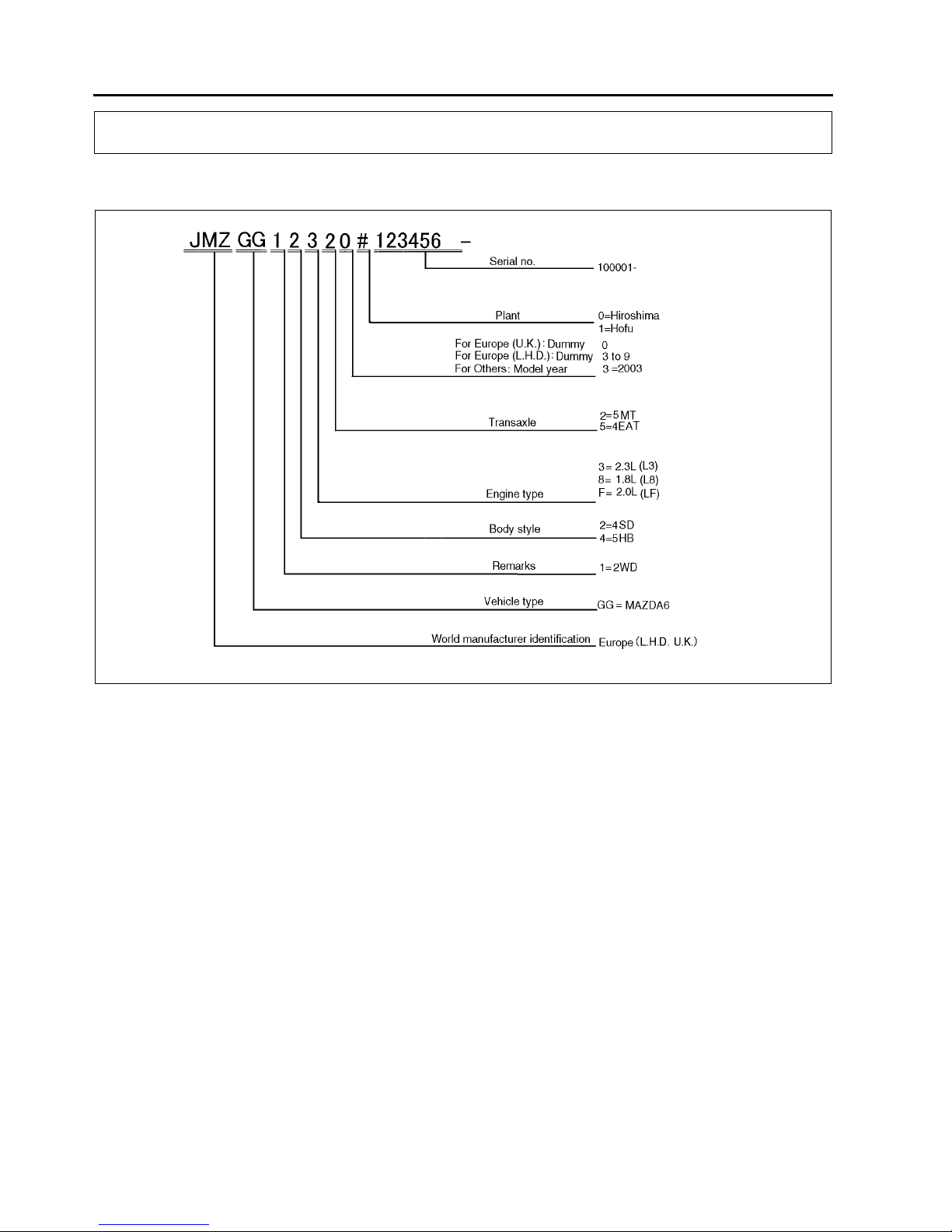
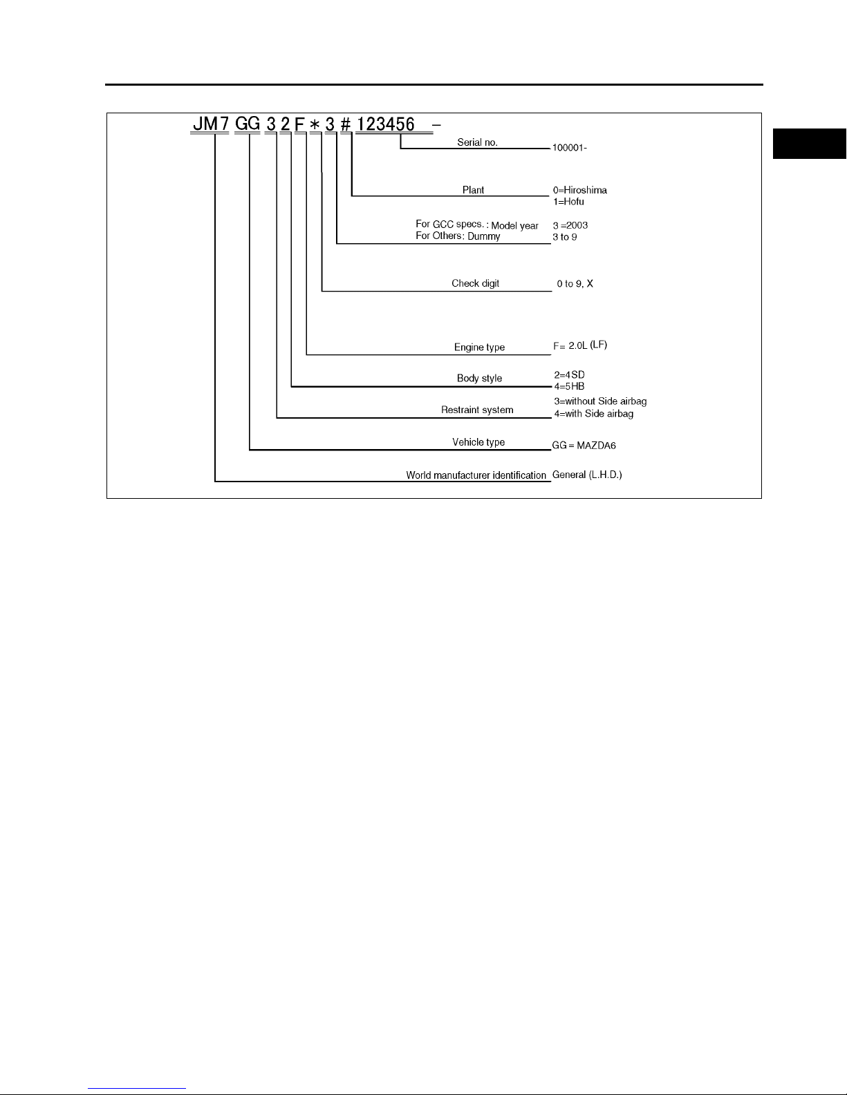
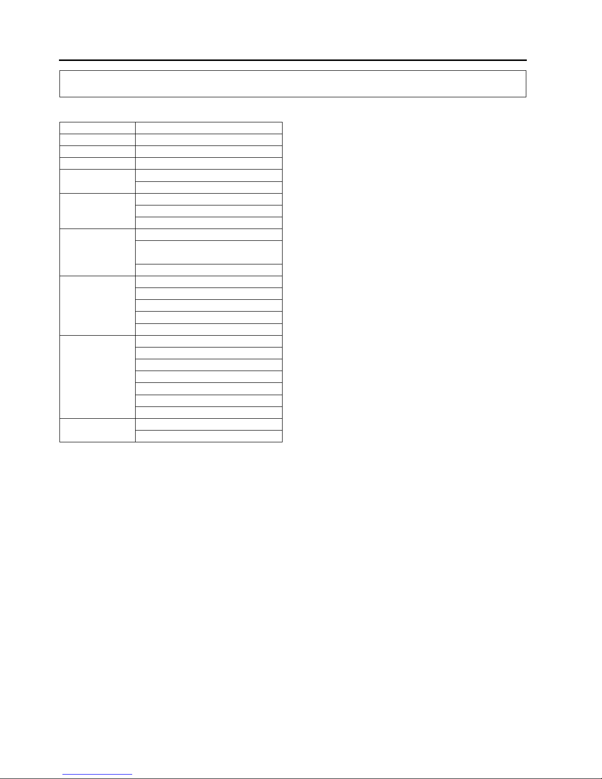
Mazda Mazda 6 Installation guide

CONTENTS
Mazda6
Training
Manual
FOREWORD
This manual explains each component or
system operation and function for
the Mazda6.
For proper repair and maintenance,
a thorough familiarization with this manual
is important, and it should always be kept
in a handy place for quick and easy
reference.
ll the contents of this manual, including
drawings and specifications, are the latest
available at the time of printing.
s modifications affecting repair or
maintenance occur, relevant information
supplementary to this volume will be made
available at Mazda dealers. This manual
should be kept up-to-date.
Mazda Motor Corporation reserves
the right to alter the specifications and
contents of this manual without obligation
or advance notice.
ll rights reserved. No part of this book
may be reproduced or used in any form or
by any means, electronic or
mechanicalincluding photocopying and
recording and the use of any kind of
information storage and retrieval
systemwithout permission in writing.
Mazda Motor Corporation
HIROSHIMA, JAPAN
PPLIC TION:
This manual is applicable to vehicles
beginning with the Vehicle Identification
Numbers (VIN) shown on the following
page.
2002 Mazda Motor Corporation
PRINTED IN The Netherlands, MARCH 2002
33591E02C
Title Section
General Information GI
Engine B
Lubrication System D
Cooling System E
Fuel and Emission Control Systems F
Engine Electrical System G
Clutch H
Manual Transaxle J
Automatic Transaxle K
Front and Rear Axles M
Steering System N
Braking System P
Suspension R
Body S
Body Electrical System T
Heater and Air Conditioner Systems U

VEHICLE IDENTIFICATION NUMBERS (VIN)
U.K. specs.
JMZ GG12820# 100001
JMZ GG14320# 100001
JMZ GG14820# 100001
JMZ GG12F20# 100001
JMZ GG12F50# 100001
JMZ GG14F20# 100001
JMZ GG14F50# 100001
European (L.H.D.) specs.
JMZ GG1232✻# 100001
JMZ GG1282✻# 100001
JMZ GG1432✻# 100001
JMZ GG1482✻# 100001
JMZ GG12F2✻# 100001
JMZ GG12F5✻# 100001
JMZ GG14F2✻# 100001
JMZ GG14F5✻# 100001
GCC specs.
JM7 GG32F✻✻# 100001
JM7 GG34F✻✻# 100001
JM7 GG42F✻✻# 100001
JM7 GG44F✻✻# 100001
RELATED MATERIALS
Engine Workshop Manual L8, LF, L3 . . . . . . . . . . . . . . 17311*02C
Manual Transaxle Workshop Manual
G35MR . . . . . . . . . . . . . . . . . . . . . . . . . . . . . . . . . . . . 17321*02C
Automatic Transaxle Workshop Manual
FN4AEL. . . . . . . . . . . . . . . . . . . . . . . . . . . . . . . . . . . . 16231098E
Automatic Transaxle Workshop Manual
Supplement FN4AEL . . . . . . . . . . . . . . . . . . . . . . . . . 17461*02C
Mazda6 Wiring Diagram
(European (L.H.D.), GCC specs.) . . . . . . . . . . . . . . . . 55391*02C
Mazda6 Wirinig Diagram
(U.K. specs.) . . . . . . . . . . . . . . . . . . . . . . . . . . . . . . . . . 55401*02C
Mazda6 Bodyshop Manual
(European (L.H.D. U.K.), GCC specs.) . . . . . . . . . . . . 33601*02C
* : Indicates the printing location
E: Europe
0: Japan

GI1
GI
GIGENERAL INFORMATION
HOW TO USE THIS MANUAL ............................. GI-2
VIN CODE.......................................................... GI-2
UNITS ................................................................... GI-4
UNITS TABLE .................................................... GI-4
NEW STANDARDS .............................................. GI-5
NEW STANDARDS TABLE ............................... GI-5

GI2
HOW TO USE THIS MANUAL
VIN CODE A6E201000001T01
European (L.H.D. U. .) specs.
HOW TO USE THIS MANUAL
A6E2021T001

HOW TO USE THIS MANUAL
GI3
GI
GCC specs.
End Of Sie
A6E2021T002

GI4
UNITS
UNITS TABLE A6E201200002T01
Conversion to SI Units (Système International d'Unités)
•All n merical val es in this man al are based on SI nits. N mbers shown in conventional nits are converted
from these val es.
Rounding Off
•Converted val es are ro nded off to the same n mber of places as the SI nit val e. For example, if the SI nit
val e is 17.2 and the val e after conversion is 37.84, the converted val e will be ro nded off to 37.8.
Upper and Lower Limits
•When the data indicates pper and lower limits, the converted val es are ro nded down if the SI nit val e is
an pper limit and ro nded p if the SI nit val e is a lower limit. Therefore, converted val es for the same SI
nit val e may differ after conversion. For example, consider 2.7 kgf/cm2 in the following specifications:
210260 kPa {2.12.7 kgf/cm2, 3038 psi}
270310 kPa {2.73.2 kgf/cm2, 3945 psi}
•The act al converted val es for 2.7 kgf/cm2 are 265 kPa and 38.4 psi. In the first specification, 2.7 is sed as
an pper limit, so the converted val es are ro nded down to 260 and 38. In the second specification, 2.7 is
sed as a lower limit, so the converted val es are ro nded p to 270 and 39.
End Of Sie
UNITS
Electrical c rrent A (ampere)
Electric power W (watt)
Electric resistance ohm
Electric voltage V (volt)
Length mm (millimeter)
in (inch)
Negative press re
kPa (kilo pascal)
mmHg (millimeters of merc ry)
inHg (inches of merc ry)
Positive press re
kPa (kilo pascal)
kgf/cm2 (kilogram force per sq are
centimeter)
psi (po nds per sq are inch)
Torq e
N·m (Newton meter)
kgf·m (kilogram force meter)
kgf·cm (kilogram force centimeter)
ft·lbf (foot po nd force)
in·lbf (inch po nd force)
Vol me
L (liter)
US qt (U.S. q art)
Imp qt (Imperial q art)
ml (milliliter)
cc (c bic centimeter)
c in (c bic inch)
fl oz (fl id o nce)
Weight g (gram)
oz (o nce)

NEW STANDARDS
GI5
GI
NEW STANDARDS TABLE A6E202800020T01
•Following is a comparison of the previo s standard and the new standard.
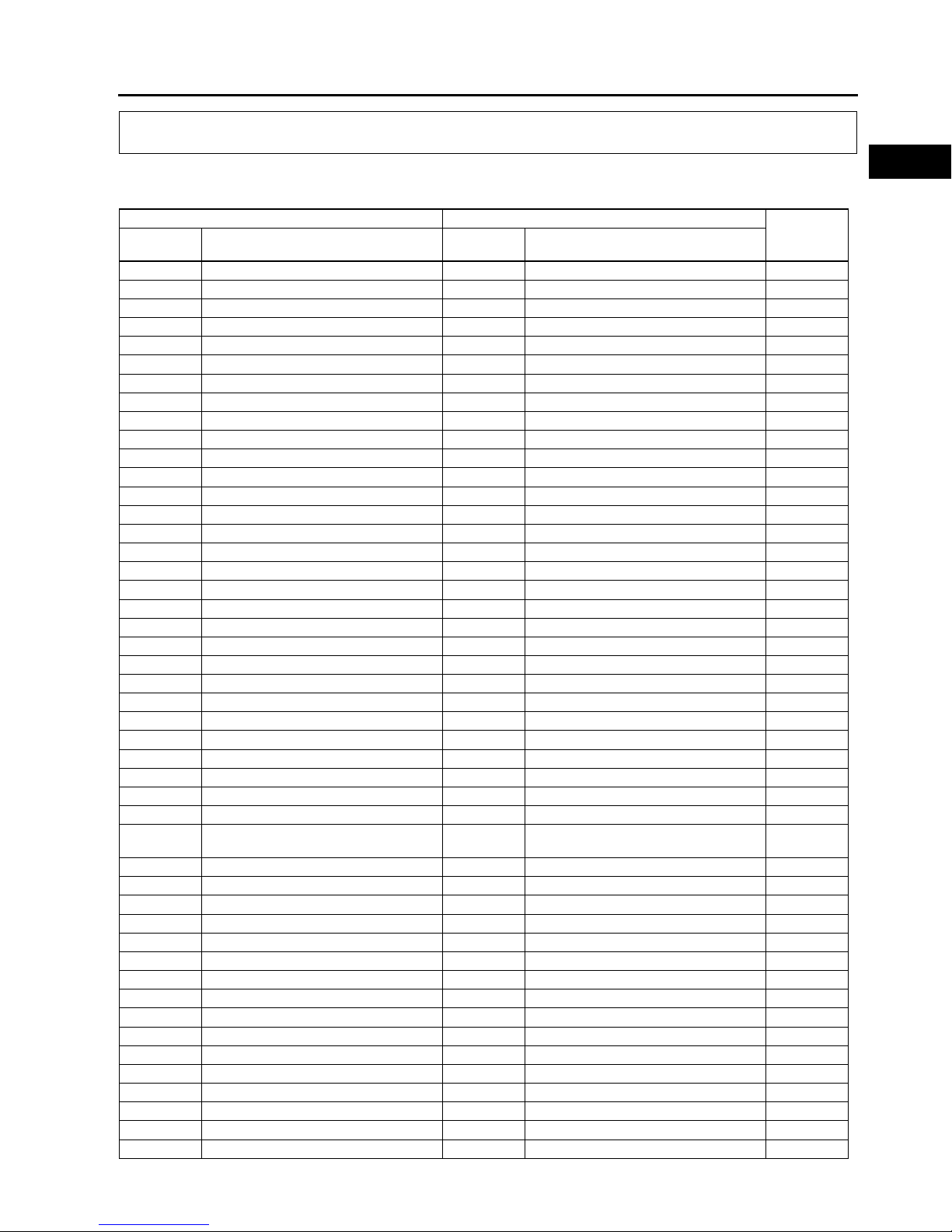
NEW STANDARDS
New Standard Previous Standard
Remark
Abbrevi-
ation Name Abbrevi-
ation Name
AP Accelerator Pedal Accelerator Pedal
ACL Air Cleaner Air Cleaner
A/C Air Conditioning Air Conditioning
BARO Barometric Press re Atmospheric Press re
B+ Battery Positive Voltage Vb Battery Voltage
Brake Switch Stoplight Switch
Calibration Resistor Corrected Resistance #6
CMP sensor Camshaft Position Sensor Crank Angle Sensor
CAC Charge Air Cooler Intercooler
CLS Closed Loop System Feedback System
CTP Closed Throttle Position F lly Closed
CPP Cl tch Pedal Position Cl tch Position
CIS Contin o s F el Injection System EGI Electronic Gasoline Injection System
CS sensor Control Sleeve Sensor CSP sensor Control Sleeve Position Sensor #6
CKP sensor Crankshaft Position Sensor Crank Angle Sensor 2
DLC Data Link Connector Diagnosis Connector
DTM Diagnostic Test Mode Test Mode #1
DTC Diagnostic Tro ble Code(s) Service Code(s)
DI Distrib tor Ignition Spark Ignition
DLI Distrib torless Ignition Direct Ignition
EI Electronic Ignition Electronic Spark Ignition #2
ECT Engine Coolant Temperat re Water Thermo
EM Engine Modification Engine Modification
Engine Speed Inp t Signal Engine RPM Signal
EVAP Evaporative Emission Evaporative Emission
EGR Exha st Gas Recirc lation Exha st Gas Recirc lation
FC Fan Control Fan Control
FF Flexible F el Flexible F el
4GR Fo rth Gear Overdrive
F el P mp Relay Circ it Opening Relay #3
FSO
solenoid F el Sh t Off Solenoid FCV F el C t Valve #6
GEN Generator Alternator
GND Gro nd Gro nd/Earth
HO2S Heated Oxygen Sensor Oxygen Sensor With heater
IAC Idle Air Control Idle Speed Control
IDM Relay Spill Valve Relay #6
Incorrect Gear Ratio
Injection P mp FIP F el Injection P mp #6
Inp t/T rbine Speed Sensor P lse Generator
IAT Intake Air Temperat re Intake Air Thermo
KS Knock Sensor Knock Sensor
MIL Malf nction Indicator Lamp Malf nction Indicator Light
MAP Manifold Absol te Press re Intake Air Press re
MAF sensor Mass Air Flow Sensor Airflow Sensor
MFL M ltiport F el Injection M ltiport F el Injection
OBD On-Board Diagnostic Diagnosis/SelfDiagnosis
OL Open Loop Open Loop

GI6
NEW STANDARDS
#1 : Diagnostic tro ble codes depend on the diagnostic test mode
#2 : Controlled by the PCM
#3 : In some models, there is a f el p mp relay that controls p mp speed. That relay is now called the f el p mp
relay (speed).
#4 : Device that controls engine and powertrain
#5 : Directly connected to exha st manifold
#6 : Part name of diesel engine
End Of Sie
O tp t Speed Sensor Vehicle Speed Sensor 1
OC Oxidation Catalytic Converter Catalytic Converter
O2S Oxygen Sensor Oxygen Sensor
PNP Park/Ne tral Position Park/Ne tral Range
PCM Control Relay Main Relay #6
PSP Power Steering Press re Power Steering Press re
PCM Powertrain Control Mod le ECU Engine Control Unit #4
Press re Control Solenoid Line Press re Solenoid Valve
PAIR P lsed Secondary Air Injection Secondary Air Injection System P lsed
injection
P mp Speed Sensor NE Sensor #6
AIR Secondary Air Injection Secondary Air Injection System
Injection
with air
p mp
SAPV Secondary Air P lse Valve Reed Valve
SFI Seq ential M ltipoint F el Injection Seq ential F el Injection
Shift Solenoid A 1-2 Shift Solenoid Valve
Shift A Solenoid Valve
Shift Solenoid B 2-3 Shift Solenoid Valve
Shift B Solenoid Valve
Shift Solenoid C 3-4 Shift Solenoid Valve
3GR Third Gear 3rd Gear
TWC Three Way Catalytic Converter Catalytic Converter
TB Throttle Body Throttle Body
TP sensor Throttle Position Sensor Throttle Sensor
TCV Timer Control Valve TCV Timing Control Valve #6
TCC Torq e Converter Cl tch Lock p Position
TCM Transmission (Transaxle) Control
Mod le ECAT Control Unit
Transmission (Transaxle) Fl id
Temperat re Sensor ATF Thermosensor
TR Transmission (Transaxle) Range Inhibitor Position
TC T rbocharger T rbocharger
VSS Vehicle Speed Sensor Vehicle Speed Sensor
VR Voltage Reg lator IC Reg lator
VAF sensor Vol me Air Flow Sensor Air flow Sensor
WUTWC Warm Up Three Way Catalytic
Converter Catalytic Converter #5
WOT Wide Open Throttle F lly Open
New Standard Previous Standard
Remark
Abbrevi-
ation Name Abbrevi-
ation Name

B1
B
BENGINE
ABBREVIATIONS ..................................................B-2
ABBREVIATIONS ................................................B-2
OUTLINE ................................................................ B-2
OUTLINE OF CONSTRUCTION..........................B-2
FEATURES .......................................................... B-2
ENGINE PERFORMANCE CURVE..................... B-3
SPECIFICATIONS ............................................... B-4
STRUCTURAL VIEW...........................................B-4
ENGINE .................................................................. B-5
CYLINDER HEAD COVER .................................. B-5
CYLINDER HEAD ............................................... B-5
CYLINDER HEAD GASKET ................................B-6
CYLINDER BLOCK ............................................. B-6
CRANKSHAFT, MAIN BEARING......................... B-8
BALANCER UNIT ................................................B-9
CRANKSHAFT PULLEY .................................... B-11
ENGINE FRONT COVER ..................................B-12
PISTON, PISTON RING, PISTON PIN ..............B-13
CONNECTING ROD,
CONNECTING ROD BEARING......................B-14
DRIVE BELT ......................................................B-15
ENGINE MOUNT ............................................... B-16
VALVE MECHANISM ........................................... B-19
VALVE MECHANISM......................................... B-19
CAMSHAFT ....................................................... B-20
CAMSHAFT SPROCKET................................... B-22
CRANKSHAFT SPROCKET .............................. B-23
TIMING CHAIN, CHAIN TENSIONER ...............B-24
VALVE, VALVE SPRING, VALVE SEAL,
VALVE GUIDE ................................................B-25
TAPPET .............................................................B-26
VALVE MECHANISM......................................... B-27
VARIABLE VALVE TIMING ACTUATOR........... B-33
OIL CONTROL VALVE (OCV) ........................... B-33

B2
ABBREVIATIONS , OUTLINE
ABBREVIATIONS A6E220102000T01
End Of Sie
OUTLINE OF CONSTRUCTION A6E220202000T01
•The new L8 engine models (1.8L) has been adopted for E ropean specs.
•The new LF engine models (2.0L) has been adopted.
•The new L3 (with variable valve timing mechanism) engine models (2.3L) has been adopted for E ropean
specs.
End Of Sie
FEATURES A6E220202000T02
Improved engine performance
•The variable valve timing mechanism has been adopted for L3 engine models (2.3L).
Reduced engine weight
•Main parts (cylinder head and cylinder block) made of al min m alloy.
Reduced engine noise and vibration
•The cylinder head is made of al min m alloy.
•The cassette type balancer nit has been adopted for the L3 engine models (2.3L).
•Silent timing chain has been adopted.
•A deep skirt type and forms the ladder frame str ct re with the integrated main bearing cap has been adopted
for the cylinder block.
•The crankshaft p lley with torsional damper has been adopted.
•The engine mo nt of pend l m type has been adopted.
Improved serviceability
•The drive belt of serpentine type has been adopted.
•Tension of the drive belt is adj sted a tomatically with an a to-tensioner.
•Timing chains have been adopted to eliminate the need for replacement.
•The engine front cover with service hole has been adopted. (for nlocking the chain adj st ratchet, and
sec ring the tensioner arm).
End Of Sie
ABBREVIATIONS
A/C Air conditioner
ABDC After bottom dead center
ATDC After top dead center
BBDC Before bottom dead center
BTDC Before bottom dead center
DOHC Do ble overhead camshaft
EX Exha st
IN Intake
OCV Oil control valve
P/S Power steering
PCV Positive crankcase ventilation
SST Special service tool
TDC Top dead center
OUTLINE

OUTLINE
B3
B
ENGINE PERFORMANCE CURVE A6E220202000T04
AME2202N001
1 Engine speed 2Otpt
3Torqe

B4
OUTLINE
End Of Sie
SPECIFICATIONS A6E220202000T03
End Of Sie
STRUCTURAL VIEW A6E220202000T05
End Of Sie
Item Specification
L8 LF L3
Type Gasoline, 4-cycle
Cylinder arrangement and n mber In-line, 4-cylinder
Comb stion chamber Pentroof
Valve system DOHC, timing chain driven, 16 valves
Displacement (ml {cc, c in}) 1,798
{1,798, 109.7}
1,999
{1,999, 121.9}
2,261
{2,261, 137.9}
Bore × stroke (mm {in}) 83.0 × 83.1
{3.27 ×3.27}
87.5 × 83.1
{3.44 ×3.27}
87.5 × 94.0
{3.44 × 3.70}
Compression ratio 10.8:1 10.8:1 10.6:1
Compression press re (kPa {kgf/cm2, psi} [rpm]) 1,750 {17.85, 253.8}
[300]
1,720 {17.54,
249.5} [300]
1,430 {14.58, 207.4}
[290]
Valve timing
IN Open BTDC (°) 4 4 025
Close ABDC (°) 33 52 037
EX Open BBDC (°)37 37 42
Close ATDC (°)4 4 5
Valve
clearance (mm {in}) IN 0.22 {0.0087} 0.28 {0.011} [Engine cold]
EX 0.27 {0.011} 0.33 {0.012} [Engine cold]
AME2202N002

ENGINE
B5
B
CYLINDER HEAD COVER A6E222410100T01
Structure
•The cylinder head cover is made of integrated al min m alloy, which is lightweight and so nd absorbent.
•The oil filler cap is a screw-in type. The boss for installing the camshaft position (CMP) sensor is provided at
the rear of the cylinder head cover.
•L3 engine models has a hole for installing the oil control (OCV) valve.
.
End Of Sie
CYLINDER HEAD A6E222410100T02
Structure
•The cylinder head is made of a high heat cond ctive, lightweight al min m alloy, which has been q enched.
•Compact, pentroof-type comb stion chambers have been adopted. The spark pl gs are mo nted at the top of
the comb stion chambers to improve comb stion efficiency.
•The intake/exha st port layo t is a cross flow type, (the angle between two valves is 39°, the two intake valves
and the two exha st valves per cylinder) which improves air intake/exha st efficiency.
•The cylinder head bolt is a plastic region tightening bolt, which is tightened in five motions. It ins res a stable
axis d ring tightening.
.
ENGINE
AME2224N001
1 Camshaft position (CMP) sensor
2 Oil control (OCV) valve attachment hole (L3)
3 Oil filler cap
AME2224N002
1 Cylinder head bolt
2 Exha st side
3 Intake side
4 Engine front side
5 The angle between two valves
6 Intake port
7 Exha st port

B6
ENGINE
End Of Sie
CYLINDER HEAD GAS ET A6E222410271T01
Str ct re
•Cylinder head gaskets are 2 layer-metal gaskets.
.
End Of Sie
CYLINDER BLOC A6E222410300T01
Structure
•The cylinder block is made of al min m alloy, which is cast with the cast iron liner, improving heat radiation and
decreasing weight.
•The cylinder block is a deep skirt type and forms the ladder frame str ct re with the integrated main bearing
cap. The water jacket of the cylinder block is a closed deck type. Its higher rigidity red ces vibration and noise.
•The cylinder block has the oil separator cover on the opposite side of the fresh air intake, the PCV (positive
crankcase ventilation) valve and the oil separator f nction with an part for installing the PCV valve, to improve
blow-by gas ventilation efficiency.
• The tab for alignment, sed to install the pper main jo rnal and the lower main bearing, has been
decommissioned.
•The main bearing cap bolt is a plastic region tightening bolt, which is to be tightened in two motions. It ins res
a stable axis d ring tightening.
AME2224N400
1 Beat plate
2Shim
3 A-A sectional view

ENGINE
B7
B
.
•The service hole for installing the SST, which is sed for detect the No.1 cylinder's TDC position, is located at
the right side of the cylinder block. The TDC position can be detected when the SST edge to ches the c tting
s rface of the No.1 co nter weight.
.
AME2224N003
1 Oil separator cover
2PCV valve
3 Main bearing cap
4 Oil separator cover attachment part
5 Cylinder block
1 Cylinder block
2 No.1 cylinder
3 Service hole
4 SST
5 No.1 cylinder TDC position
6 No.1 piston
7 Crankshaft co nter
AME2224N004

B8
ENGINE
End Of Sie
CRAN SHAFT, MAIN BEARING A6E222411301T01
Structure
•Cast iron 5 axle-hole 4 co nter weight has been adopted for the L8 engine models and LF engine models
crankshafts.
•Cast iron 5 axle-hole 8 co nter weight has been adopted for the L3 engine models crankshaft. The shrinkage
fitted drive gear is attached to the crankshaft and the crankshaft drives the balance shaft.
•The conventional positioning key has been decommissioned and the tightening press re of the crankshaft
p lley tightening bolt sec res the installation part of the crankshaft sprocket. When installing the crankshaft
sprocket, always se the SST and align the No.1 cylinder to TDC.
.
•The oil line for s pplying oil to each jo rnal is provided in the crankshaft. And the crank pin and the fillets on
both sides of jo rnal are rolled so that they bear the heavy loads.
.
•The pper and lower main bearings are made of al min m alloy and the pper side No.3 jo rnal bearing is
integrated with the thr st bearing. The pper main bearing has the oil grooves and the oil holes.
•The pper and lower bearings' positioning tabs for installing the main jo rnal have been decommissioned.
•Meas re and attach the main bearings ( pper and lower) so that they are positioned at the center the main
bearing cap.
AME2224N005
1Drive gear
AME2224N006
1Oil passage 2 Fillet roll area

ENGINE
B9
B
.
•Three kinds of main bearings are available depending on the oil clearance.
(mm {in})
End Of Sie
BALANCER UNIT A6E222411301T02
Outline
•The cassette type balancer, which is separated
from the engine, has been adopted for the L3
engine models to red ce vibration from the
engine..
AME2224N007
1 Upper main bearing
2 Lower main bearing
3 Thr st bearing
4 S pplying engine oil
5 2 holes S pplying engine oil
6 Main bearing cap
7 Main bearing
Bearing
size Color Bearing thickness
Standard Green 2.5062.509 {0.09870.0988}
0.25 {0.01}
Oversize 2.6282.634 {0.10350.1037}
0.50 {0.02}
Oversize 2.7532.759 {0.10840.1086}
1 Cassette type balancer nit
2 balance shaft
AME2224N401

B10
ENGINE
Structure
•The balancer nit is config red with two balancer shafts (No.1 and No.2) with weights, the balancer nit case
and the adj st shim which adj sts the amo nt of backlash in the crankshaft.
•The two balancer shafts (No.1 and No.2) are driven by the drive gear which is attached to the crankshaft.
•The balancer nit cannot be disassembled beca se it is a precision nit.
Operation
•The rotary motion is transmitted from the drive gear, which is between the back of the No.3 cylinder and the
No.4 main jo rnal, directly to the No.1 balance shaft with driven gear. Then the balance nit transmits the
rotation motion to the No.2 balance shaft. The ratio of gears, which are attached to No.1 and No. 2 balancer
shafts, has been set so that the gear rotates at twice the velocity of the crankshaft. The balancer shaft's rotation
velocity co nterbalances (generate the force in the opposite direction) the rotation inertial force (secondary
inertial rotation force) from the crankshaft.
.
•Replace the adj st shim to adj st backlash. There are 40 kinds of adj ster shim depending on the thickness.
To determine the kind, check the engraved identification mark (2 digits) on the adj st shim.
AME2224N402
1 Adj st shim
2 Crankshaft
3 Engine front
4 Balancer nit case
5Weights
6 No.2 balance shaft
7 Drive gear
8 No.1 balance shaft with driven gear

ENGINE
B11
B
.
End Of Sie
CRAN SHAFT PULLEY A6E222411371T01
Structure
•The crankshaft position (CKP) signal detecting blade has been adopted for the crankshaft p lley. And the
torsional damper, which prevents the crankshaft from wobbling, has also been adopted for the crankshaft.
•The positioning key slot, which is sed for attaching the p lley to the crankshaft, has been decommissioned.
For aligning the crankshaft p lley to the crankshaft, se the positioning hole on the engine front cover and the
crankshaft p lley.
•Crankshaft p lley rock bolt is the plastic region tightening bolt, which can be tightened in 2 motions. It ins res a
stable axis d ring tightening.
.
End Of Sie
AME2224N403
1 Cylinder block 2 Engraved identification mark (2 digits)
1 Elevation view
2 Sectional view
3 Braid for CKP sensor signal detection
4 Hole for p lley positioning
5 Torsional damper
AME2224N012

B12
ENGINE
ENGINE FRONT COVER A6E222401001T01
Structure
•The engine front cover is made of al min m alloy, and is integrated with the No.3 engine-mo nting bracket, to
improve noise absorption and decrease weight.
•The hole for crankshaft p lley positioning bolt, the service hole for nlocking the chain adj ster ratchet, and the
service hole for sec ring the tensioner arm when loosening the timing chain, are on the engine front cover.
•The oil line and the integrated oil filter are on the L3 engine front cover.
.
End Of Sie
AME2224N011
1 Elevational view
2 Service hole for tensioner arm fixation
3 Service hole for chain tensioner lock release
4 No.3 engine mo nt bracket
5 Bolt hole crankshaft p lley positioning
6 Back view
7 Oil filter
8 Oil passage to OCV
Other manuals for Mazda 6
24
Table of contents
Other Mazda Automobile manuals

Mazda
Mazda Mazda6 2011 User manual

Mazda
Mazda MX-5 Miata User manual

Mazda
Mazda 2014 MX-5 Miata User manual

Mazda
Mazda MX-30 2020 User manual

Mazda
Mazda 6 2002 User manual

Mazda
Mazda 1978 GLC Instructions for use

Mazda
Mazda Mazda 6 User manual

Mazda
Mazda MAZDA3 2011 User manual

Mazda
Mazda 2004 MPV User manual

Mazda
Mazda Mazda 6 Guide

Mazda
Mazda CX-9 2021 User manual

Mazda
Mazda RX-7 User manual

Mazda
Mazda 2013 CX-5 Instruction manual

Mazda
Mazda RX-8 User manual

Mazda
Mazda 2 Operating and installation instructions

Mazda
Mazda 2010 CX-7 Guide

Mazda
Mazda 1984 RX7 Setup guide

Mazda
Mazda 2009 CX-7 User manual

Mazda
Mazda MX-5 Miata Guide

Mazda
Mazda 2009 CX-9 Guide