KALE AIRFREE Series User manual

NO: KL-YS-SMSEN-0813
SHVLS FAN
www.kalefans.net
KaLe Environmental Technology(Shanghai)Corp.
Tel: +86-18016245385 Fax: 021-57685025
Web:www.kalefans.net Email:[email protected]
Origin: China
ENGLISH
SHVLS FAN
KALEFANS RSHVLS
AIRFREE
TM

INSTRUCTION MANUAL
www.kalefans.net
Contents
-1-
Preface������������������������2
1. Product Introduction����������������...3
2. Product Components����������������..4
2.1 Components and Parts���������������..5
2.2 Product Packing������������������.6
3. Controller Panel nad Display Description��������.7
4. Product Operation�����������������...8
5. Safety Caution�������������������..8
6. Troubleshooting������������������...9
6.1 Interpretation for Error Codes������������..9
7. Customer Service�����������������....13
8. Product Use Condition���������������...13
9. Warranty and Maintenance�������������....14

Preface
-nce. More importantly, our products have
Thanks and congratulate for your purchasing of SHVLS Airfree series big wall fan! Now you have acquired the most effective shortcuts
No matter in the industrial or utility applications, it possesses relatively high cost performa
passed the strict quality inspection and a variety of safety tests, and you can rest assured
If you have any questions and comments to our products,contract us through
+86-18016245385
, or access to our website:
www.kalefans.net. Before the usage, please make sure that you have read the operation instruction manual.
-2-
INSTRUCTION MANUAL
AIRFREE SERIES
the operation.
to pass a cool summer and warm winter.

Airfree Series
Product Parameter
INSTRUCTION MANUAL
www.kalefans.net
1881 mm
1980 mm
374 mm
Dimensions(WxHxD) 1980mmx 1881mm x 374mm
Max speed 320r/min
Range of wind speeds 0-36m (Wind speed 7m/s-1.5m/s)
Driving Motor PMSM Motor
Motor Power 0.55 kW
Inner Power 1P/AC220V
Full-load current 1.7 A
Protection level s IP55
Wight 136kg
Note:
1. Weight: the weight in table doesn’t contain controller, top connection parts etc.;
2. Spec:the above-mentioned product size is standard size, other size can be customized.;
3. Input power: 1P/AC220V;
4. Driving motor:PMSM motor;
Air Volume 1208m³/min

-4-
2. Product Components
INSTRUCTION MANUAL
AIRFREE SERIES
1
2
3
4
5
Metal Grid
Mounting bracket
PMSM motor
Fan blade
Winglet
1
2
3
4
5

Motor Drawing
Controller Drawing
-5-
2.1 Components and Parts
INSTRUCTION MANUAL
www.kalefans. net
a: Stator axis
b: Rotor disc
c: Motor cover
a
b
c
Knob master switch
Input wiring terminal
Start /speed regulating switch
Output wiring terminal
LCD screen
Operation Guide QR code
RJ45 Ethernet interface
Control box body

2.2 Product Packing
-6-
INSTRUCTION MANUAL
AIRFREE SERIES
NO
DESCRIPTION
NO
DESCRIPTION
1
2
3
4
5
6
7
8
9
10
11
12
Packing Details
Motor Fan adjusting base
Blade retainer
Connector
Power cable
Fasteners
Controller
Fan blade
Steel mesh
Extension tube
Mouting brackets for wall
Supporting pieces for mesh
Packing Information

-7-
INSTRUCTION MANUAL
www.kalefans.net
3. Specification of parameters for cont rol system
LCD display status confirmation
User setting interface description
After the controller is powered on, when the switch points to ON, the machine is
powered on, and the LCD displays: given rotating speed, operating current, input
voltage, operating status, whether "output rotating speed" is locked, failure
interface and other specific interface information as follows:
Operating interface
Standby interface
Accelerating interface
Setting interface
Failure interface
Decelerating interface
User setting interface description
In the standby state, long press (more than 2s) knob to enter the " Setting interface",
and the setting interface functions are as follows:
S00
S01
S02
S03
Top left: Setting rotating speed
Lower left: Voltage
Right: Operating
Top left: Setting rotating speed
Lower left: Voltage
Right: Standby
Top left: Setting rotating speed
Lower left: Voltage
Right: Accelerating
Line1: Setting
Line2: S00 Return
Line3: S01 Rotating speed unlocked
Line4: S02 Motor Self-learning
Top left: Failure Code
Lower left: Please contact factory
Right: ER Logo
Top left: Setting rotating speed
Lower left: Voltage
Right: Decelerating
Function code Description Explaination
Reture
Rotating speed unlocked/
rotating speed locked
Motor Self-learning
Operation direction switch
Function can be used to return to the main
interface/if it doesn’t return by this function,
and it will automatically return to the main
interface after 10s.
After locked: the adjusting knob will not change
the given rotating speed to prevent accidental
touch, and select this function again to unlock
the rotating speed.
The motor operation control effect is better after
self-learning.
If the motor runs in the wrong direction, the motor
direction can be switched by this function.
RUN
Fan Speed
50 RPM
1.5
V
ER
E.0LF [1909]
contact us
Set
S00 return
S01 Speed lock
S02 Motor learning
Fan Speed
50 RPM
1.5
V
Fan Speed
50 RPM
1.5
V
Fan Speed
50 RPM
1.5
V
ACCEL
DECEL
Error code
STANDBY
S02 Motor learning

-8-
INSTRUCTION MANUAL
AIRFREE SERIES
4. Operation instructions
Operation Instructions
1. Please read the precautions very carefully before you start use.
2. Please confirm the wirings have been connected correctly, then
turn the main knob to “ON”. Now it’s powered on.
3. Press twice “start speed switch” to use “start speed switch” to
control the rotation speed.
4. Press twice “rotation button” to stop the motor. Then turn the
main knob to “OFF” the rotation completely stop.
5. You can also achieve the operation guide by scanning the QR
code.
5. Safety precautions
Do not bend the fan blades when installing, adjusting, and cleaning the fan, otherwise it will damage the equipment or affect the use of the equipment.
Before turn on the power please make sure that the input voltage of the fan is consistent with the power supply voltage.
Do not operate maintenance when the power is on.
Please correctly connect the input and output power cables and ground cables according to the markings on the control box.
After confirming that the wiring is correct, the product is energized for trial operation. After the trial operation is correct, it can run normally for a long
time.
If the fan fails and cannot be reset, please contact the manufacturer.
Do not operate the damaged equipment, otherwise it will bring unexpected and serious consequences.
It is strictly prohibited to run the fan when the safety space is insufficient.
It is strictly forbidden to work inside the fan operating space. Please confirm whether there are obstacles before turning on the fan.
It is recommended that before the machine is powered off, please press the "knob key" to stop the machine, and turn off the power after the device has
completely stopped rotating.
If the machine has not been used for more than 2 months, please pre-charge the product when it is used next time: Turn on the power and waiting more
than 15mins to start the rotation.
Warning: Before operation please read the manual very carefully. Remove obstacles in the operating area to ensure
that the fan runs with safe distance. Before operate any maintenance please make sure you already turned off the
power supply. The operation must be done by professionals to avoid being injured.
Attention
1. Make sure that there are no obstacles and potential hazards in
the fan operating space.
2. Make sure that the input power is correct and meet the product
requirements.
3. Make sure that the speed knob points to the minimum position.
4. Start the equipment and turn the switch from “stop” to “run”.
5. After the fan runs, adjust the rotation speed knob to achieve the
best effect.
1. Stop the equipment and shut down the controller strictly
according to the operating instructions;
2. Please do not cut the power off during the running.
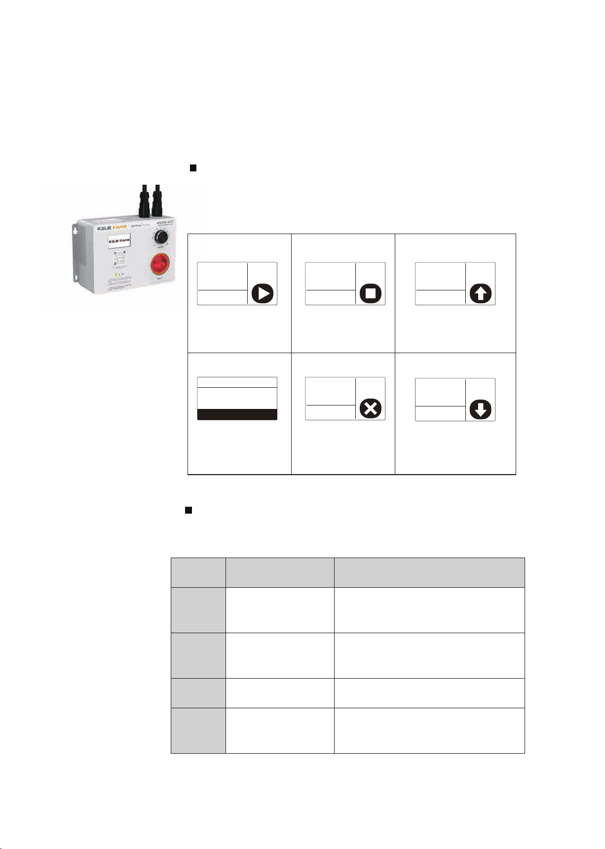
How to start: How to stop:
Rotation master button
Start speed switch
LCD Screen
Function Description:
1. LED display: The user does not have any operation on the
product within 1 minute, the LCD screen turns from bright to dark,
and the brightness is restored after operation.
2. Main switch: When the switch points to OFF , it powered off;
when the switch points to ON , it powered on.
3. Rotation speed button: multi-function knob. Please check the
above table to know the details.
2. Main switch: When the switch points to OFF , it powered off;
when the switch points to ON , it powered on.
Function Adjust Rotation speed Start, Stop button Malfunction Reset
Definition
Clockwise rotate the
“Rotation speed” button
to increase speed.
And anticlockwise to slow
down the speed.
Press once
“Rotation speed”
button to start
and stop.
When malfunction appears,
press once “Rotation speed”
button to reset it. If the reset
doesn’t work you should
contact KALE following the
guide shown on screen.
Notice: Short press of "Rotation speed switch": the duration is less than 2s;
Long press of "Rotation speed switch": more than 2s;

-9-
INSTRUCTION MANUAL
www.kalefans.net
Warning!
The installation and circuit wiring work must be operated by professionally qualified person. Please use the device parts specified by our
company. Do not cut off the power supply while the fan is running, otherwise the fan will be damaged. The power should be cut off after the
fan completely stopped. When the fan is running, do not turn the knob directly to the reset position. Otherwise it will cause mechanical failure.
6. Failure recovery
Common reasons for the fan not working properly:
1. The external power supply of the control box is invalid.
2. If you turn on the main switch but the fan still does not run please contact KALE Environmental Technology (Shanghai) Co., Ltd. to
communicate with our professional engineers.
Non-professionals are strictly prohibited from opening the controller box! If maintenance or adjustment is required, the operation must be
performed by professionals trained by KALE Environmental Technology (Shanghai) Co., Ltd. or under the guidance of our company's engineers.
If you find any damage or abnormal noise, please stop the operation as soon as possible, cut off the power, and contact KALE after-sales
service department. Note: Equipment damage caused by abnormal use is not contained by the product warranty of KALE FANS. Our company
shall not be liable for personal injury and equipment damage caused by your failure to comply with the contents of this manual.
6.1 Error code:
Failure, warning
(Notice) When the product has a fault code, please press the knob button to reset the fault;
if the fault cannot be reset, please contact KALE.
Common fault display and countermeasures:
E. oC1/E.oC2/E.oC3
E. oU1/E.oU2/E.oU3
E. Lu
E. oL1
E. oL2
E. iLF
E. oLFxx
E. oH2
E. TExx
E. SPD
(Notice) The number xx after the above fault indication indicates a fault occurred in a certain
phase of a three-phase circuit under different operating conditions.
ER Code Description
Acceleration/deceleration/constant speed/over current
Acceleration/deceleration/constant speed/overvoltage
Undervoltage during operation
Motor overload
Controller overload
Input phase loss
U/V/W Phase output phase loss
IGBT Module over temperature
Self-learning output current exceeds limit
Rapid failure
When a fault occurs, the controller cannot operate. The following table explains the cause of the fault and corresponding measures.
Note: All faults must be reset to eliminate them.

-10-
INSTRUCTION MANUAL
AIRFREE SERIES
Code
Desc.
Reason
Solution
E. oCxx
Mid-
acceleration/mid-
deceleration/mid-
speed/over-current
fault
Overload Reducing load or replacing impulse load of large capacity
controller requires reducing load change frequency or
replacing larger capacity controller
Short circuit to the output
side of the controller
Check main circuit, eliminate short circuit
Motor damaged
Measure the resistance between the lines of the motor and
replace the motor immediately if conduction
Too short
acceleration/deceleration
time
Increase F01.22 [acceleration time 1] increase F01.23
[deceleration time 1] replace bulk control
Overvoltage suppression of
rising frequency may result
in accelerated overcurrent
fault
Decrease overvoltage gain F10.13[ overvoltage gain)
Overflow suppression of
frequency reduction
resulting in deceleration
over current fault
Increase overcurrent suppression gain F10.02[ overcurrent
suppression gain]
Controller output cable
exceeds allowable
maximum
Shorten output cable or add sinusoidal filter
Mis-operation caused by
interference
Check the wiring of control circuit, main circuit and ground,
remove interference source
Notice: this fault is detected when the output current of the controller exceeds the overcurrent point.
Code
Desc.
Reason
Solution
E. oUxx
Mid-
acceleration/mo
derate/mid-
speed/stop/over
-voltage fault
High voltage
Reduce the supply voltage to a specified rang
Controller output or motor
short circuit
Check main circuit wiring, eliminate short circuit
Too short
acceleration/deceleration
time
Determine whether the acceleration stops. The fault
detection increases F01.22[ acceleration time 1] increases
F01.23[ deceleration time 1]
Overvoltage suppression of
frequency rise may result in
accelerated overvoltage
fault
Increase overvoltage suppression gain F10.13[ overvoltage
suppression gain]
Over-current suppression of
frequency-lowering
overvoltage fault
Decreasing overcurrent suppression gain F10.02[ overcurrent
suppression gain] and reducing load
Surge voltage mixed with
input voltage
Add reactor to input side
Improper setting of speed
tracking parameters
Change of Speed Tracking Parameters (F07.25~F07.28)
Notice: this fault is detected when the bus voltage exceeds the overvoltage point. Three-phase input overvoltage point is 820 V,
single-phase input overvoltage point is 400 V.

-11-
INSTRUCTION MANUAL
www.kalefans.net
Code
Desc.
Reason
Solution
E. Lu
Under pressure in
operation
Power outages or
instantaneous power
outages
Check power and reset
Input Power Lack Phase
Confirmation of Main Circuit Wiring
Excessive input voltage
fluctuations
Improve the power supply to meet the rated voltage of the
controller if the main circuit power supply is no problem,
check the main circuit side of the electromagnetic
contactor whether there is a problem
Notice: this fault is detected when the bus voltage is lower than the under voltage protection point (F10.19) when the controller is
running
Code
Desc.
Reason
Solution
E. oL1
Motor overload
Overload
Reduce the load and increase the curve coefficient of
overload protection
Acceleration and
deceleration time set too
small
Increase F01.22,F01.23 (Acceleration and deceleration time)
Torque lift set too large
Decrease F04.01[ torque increase]
V/F curve setting is not
appropriate+
To determine the relationship between voltage and
frequency of V/F curve setting, modify F04.00[VF curve
setting]
Modify the custom V/F curve related parameters
(F04.10~F04.19)
The characteristics of
electronic thermal relay are
inconsistent with the
characteristics of motor
load.
Use of external thermal relays
Abnormal output current
due to input missing phase
Check the main loop to remove input phase
Code
Desc.
Reason
Solution
E. oL2
Controller
Overload
Overload
Reduce load
Increase the curve coefficient of overload protection of motor
Acceleration and
deceleration time too
short
Increase F01.22、F01.23[ acceleration and deceleration time]
Decrease F04.01[ torque increase]
Torque lift set too large
Decrease F04.01[ torque increa
V/F curve setting is not
appropria
To determine the relationship between voltage and frequency
of V/F curve setting, modify F04.00[VF curve setting]
Modify the custom V/F curve related parameters
(F04.10~F04.19)
Abnormal output current
due to input missing
phase
Check the main loop to remove input phase

-12-
INSTRUCTION MANUAL
AIRFREE SERIES
Code
Desc.
Reason
Solution
E.iLF
Input missing
phase
Loosening of main circuit
terminal of controller
Tighten the screw and restart
Excessive input voltage
fluctuations
Improve the power supply to meet the rated voltage of the
controller if the main circuit power supply is no problem,
check the main circuit side of the electromagnetic contactor
whether there is a problem
Three-phase voltage
imbalance
Confirm if there is a problem with the input voltage and
improve the power imbalance
Code
Desc.
Reason
Solution
E. oLFxx
Output Missing
Phase
Controller output side
U/V/W/ phase break
Check that the motor U/V/W/ phase connection is normal
check that the controller output terminal screw is loose
Motor damage
Measure the resistance between the motor wires, and replace
the motor immediately if it is connected
Low motor power
Reset controller or motor power
Code
Desc.
Reason
Solution
E. oH2
IGBT module
overheating
Excessive ambient
temperature
Reduce the ambient temperature of the controller
Overload
Reduce load
Decreased F01.40[ Carrier Set]
Fan fault
Make sure that the fan is running normally. When the fan is
abnormal, replace the fan and start up again
Code
Desc.
Reason
Solution
E. TExx
Self-learning
failures
The output current of the
controller exceeds the
upper and lower limits
Check if the motor connection is correct, re-learn after reset,
still report failure to seek factory support
Notice: where "xx" is self-learning fault sub code.
Code
Desc.
Reason
Solution
E. SPD
Rapid failure
控制器应用故障Controller
application
Seek technical support from manufacturers
Improper setting of
relevant parameters for
rapid detection
Rapid Detection Threshold and F10.45[ Rapid Detection Time]
Notice: the percentage of output motor speed relative to F01.10 [maximum frequency] is greater than F10.44 [ rapid detection
threshold], and the fault is reported after continuous F10.45[ of rapid detection time. By F10.43 [the rapid protection action], the
fault detection and the motor operation mode can be set when the fault is detected.

-13-
INSTRUCTION MANUAL
www.kalefans.net
7. User Service
8. Product working condition
After-sales service is a very important link to the stability of equipment operation. Because of this, KALE Environmental
Technology (Shanghai) Co., Ltd. always takes it as its responsibility to provide users with high-quality products and perfect
after-sales service. At present, KALE Environment has set up sales and after-sales service centers in all provinces, cities and
regions across the country to ensure that customers are provided with thoughtful, fast, high-quality and all-round after-sales
service in the first time, so that users can buy and use with ease.
Product technical support
Combined with the installation, commissioning and operation process of fan equipment, the user’s management and
maintenance personnel will be trained for free on the basic knowledge, use, and maintenance techniques of the equipment
in a planned way, and the relevant qualifications and certificates of the equipment will be provided to ensure the long-term
stable operation of the equipment .
If you need relevant support, you can use the following channels:
1. Log in to our company's official website www.kalefans.net, browse and download the latest product technical instructions;
2. Call our company at +86-18016245385 for support;
3. Call the corresponding sales and service personnel for support.
Our company adheres to the principle of customer first and provides you with the best quality service.
Environment Condition
Installation Space Interior
Environment
Temperature
-15℃~55℃
To improve reliability, use the product where the temperature does
not change sharply.
Humidity Less than 95% RH
Environment
Non-corrosive, flammable gases, Metal powder, oil, water and other
foreign bodies will not enter the controller inside the place.
Less salty.
Enviroment Altitude Less than 1000m

-14-
INSTRUCTION MANUAL
AIRFREE SERIES
9. Repair and maintenance
Our product design is maintenance-free, but in order to ensure the fan's long life and normal operation, the fan should also be
maintained, especially for applications in harsh environments. For any maintenance on the fan or inverter controller, please
make sure that the fan stops running and cut off the power supply of the controller to protect personnel.
Time interval -Recommended maintenance work content
Trial run -Check the fan for abnormal running sound or vibration
Every 2500 hours of work -Frequency conversion controller dust removal
-Fan blade dust removal
Every 5000 hours of work -Check mechanical fasteners to ensure that there is no looseness
-Check the wire cable to make sure there is no damage
If the fan produces severe noise or vibration during abnormal operation, it indicates that a mechanical part is damaged. At this
time, it should be shut down immediately and a thorough inspection should be done.
Product warranty
Product warranty period: 24 months. For failures that occur during the warranty period, please do not try to solve it by yourself.
Our company can send professional and technical personnel to provide free technical support. But the following are paid
services:
* Failure caused by incorrect use of your company.
* Occasions where a malfunction occurs due to your company's privately modifying the company's products.
* Occasions where failures are caused by natural disasters and fires.
* When the warranty period is exceeded.
* Other occasions where failures are caused by reasons that are not our company's responsibility.
The above-mentioned services are limited to mainland China, and the Shanghai company does not accept fault diagnosis and
handling abroad. If customers want to provide foreign after-sales service, they need to sign a paid foreign service contract. This
product is produced under strict quality management, and each set of products has passed strict testing procedures before
leaving the factory.
When used in occasions where a major accident or loss will occur due to a product failure, please configure relevant safety
measures.
Table of contents
Popular Fan manuals by other brands

Applica
Applica C163CM Use and care book

Mitsubishi Electric
Mitsubishi Electric VL-100ZSKRT-E operating instructions

Faro Barcelona
Faro Barcelona icaria Series manual

Craftmade
Craftmade Salerno SA52 Specifications

Home Decorators Collection
Home Decorators Collection HERITAGE POINT AM909-CB manual

LUCCI
LUCCI NEWPORT Installation, operation, maintenance & warranty information