Kanga Products Rooster Guide

Rooster CW Transceiver Rev6 Page 1 of 33 12/02/2024
‘Rooster’CW 40m or 30m Transceiver
Kit Manual and User Guide
Rev 6 12/02/2024
Easy Build 40m or 30m Crystal controlled Transceiver.
Direct Conversion Design
Part Pre-installed SMD design
approx 20 parts to fit, No coils to wind!
Single Frequency Crystal controlled operation
Front panel RIT control
approx. 2 Watts RF Output(40m), 1.5 Watts (30m )
Active Audio Filter
Sinewave CW Sidetone
Visual RX/TX indicator
10.5-14v DC Operation
Supplied with Strong Aluminium Case

Rooster CW Transceiver Rev6 Page 2 of 33 12/02/2024
These instructions are for either the 40m or 30m
kit version of the Rooster
Introduction
Welcome to the Rooster. The Rooster is designed to be a single evening project that will be
fun to build and even more fun to use. The Rooster is intended to be a replacement for the
FOXX3 kit Kanga offered for many years. The FOXX3 was very popular but had a few issues
that we wanted to address with its replacement. We wanted a simple transceiver kit that
offered better sensitivity and selectivity, more power and a purpose made enclosure.
The Rooster was first offered at the RSGB convention in 2023 to beta testers and following
feedback the Rooster design was updated to this version. Now available for 40m or 30m.
The design is based around a standard SA/NE612 front end mixer/oscillator with an op-amp
audio amplifier and active audio filter. The transmitter also shares the NE612 oscillator and
buffers the VFO signal before feeding it to a high gain PA stage giving approx. 2 watts of RF
on 40m or around 1.5 watts on 30m
The kit uses a mix of SMD and though hole parts, ALL the SMD parts are pre-installed but
still leaving about 20 parts to fit to complete the transceiver. The kit can be completed in
around an hour by an experienced builder and would be a good choice for an intermediate
level build-a-thon option.
The Rooster will require a suitable antenna with a low SWR.
Disclaimer
The kit is designed to be built by Ham radio enthusiasts and in order to use the finished
product you need to hold a valid ham Radio licence that permits operation on the Rooster
frequency in your locality.
We offer the kit as is and do not guarantee the kit assembled by yourself can meet your local
regulatory requirements, including spurious, environmental or other requirements.
I suggest that you always use the online version of the instructions, they are updated from
feedback from builders as its received and of course are in full colour which helps the build.

Rooster CW Transceiver Rev6 Page 3 of 33 12/02/2024
Parts Inventory
The parts are presented in a long strip of clear tubing, separated in sections. Each section
covers a small number of stages in the instructions, only open the section you are working
on at that time so you don’t lose any parts. Start at the end with the DC connectors and
3.5mm PCB sockets.
Item
Qty
Value
Comment
Enclosure
1
Rooster Aluminium Case
Enclosure
PCB
1
Rooster PCB
SMD Parts Pre-fitted
Parts Pack Section 1
DC PWR SKT
1
2.1mm DC Power Socket
PWR
3.5mm Jack
2
3.5 mm Stereo Type
PHONES/KEY
Capacitor
1
10nF MLCC Cap
C16 (See Stage 3 Notes)
Q4
1
2N3906
Transistor Q4
Q5
1
2N4401
Transistor Q5
Diode
1
PA Protection Diode
D6
Parts Pack Section 2
NE602
1
Mixer IC on adapter board
IC1
4 Way Strip Pins
2
Mixer Mounting Pin Strips
Strip Pins (may be fitted to IC1
IC Socket
1
8 way IC Socket
IC1
Parts Pack Section 3
RIT
1
10K Potentiometer & Knob
TUNE
BNC
1
BNC Screened Socket
ANT
Thermal Pad
1
T226 Thermal Pad
Thermal Pad
Q6
1
2SC1162
Transistor Q6 PA Transistor
LED
1
Dual Colour LED
LED
Feet
4
Rubber Feet
Feet
Parts Pack Section 4
Rooster Front Panel
1
Front Panel
Punched and printed
Rooster Rear Panel
1
Rear Panel
Aluminium Rear Panel
Parts Pack Section 5
M3 Nut
1
M3 Black Nut
PA transistor Mounting Nut
M3 Screw
5
M3 Black Screw
Panel Screws

Rooster CW Transceiver Rev6 Page 4 of 33 12/02/2024
Band Packs
40m Pack
Parts Pack 40m
L1
1
100uH
See Instructions for colours
L2
1
10uH
See Instructions for colours
L3
1
1uH
See Instructions for colours
L4
1
1uH
See Instructions for colours
L5
1
3.3uH
See Instructions for colours
XTAL
3
40m Crystal
X1, X2, X3
TRIMMER
1
4-20PF Trimmer (Red)
C26
Capacitor
1
100pf
C29
30m Pack
Parts Pack 30m
L1
1
100uH
See Instructions for colours
L2
1
6.8uH
See Instructions for colours
L3
1
0.68uH
See Instructions for colours
L4
1
0.68uH
See Instructions for colours
L5
1
3.3uH
See Instructions for colours
XTAL
3
30m Crystal
X1, X2, X3
TRIMMER
1
6-40PF Trimmer (Yellow)
C26
Capacitor
1
470pf
C29
Important
The Rooster is a relatively easy to build transceiver BUT you need to carefully follow the
instructions, do not move on a stage until you are sure that you have completed the
previous stage correctly and fully. All parts must be fitted neatly and their leads trimmed
flush. I cannot stress strongly enough that unless you follow the instructions and make
sure that each part is fitted correctly as indicated in these instructions you will not
successfully complete the kit.
Get familiar with the main PCB.
The photos are showing the 40m Board, when there is a difference the instructions for the
30m build will show the different steps needed. The difference is really the crystals and the
Low pass filter values.

Rooster CW Transceiver Rev6 Page 5 of 33 12/02/2024
You can see many parts are pre-fitted for you, there are about 20 parts left for you to fit.
Some of the parts are close together so you will need to take extra care when soldering,
make sure all the parts are fitted flush to the board if the instructions call for it and trim the
leads as flush to the board as you can. There is not a lot of room under the board when
fitted in the case.
When fitting parts do not bend the leads so that they are flat against the board to hold them
in place. A slight bend of the leads is all that is needed to hold the part in place while you
solder it. Bending them flat against the board and soldering/trimming increases the chances
of forming shorts to the ground layer.
The parts for the kit are in a number of sections, start with section 1. That is the end with
the DC and 3.5mm sockets, this will cover the first few stages of the build.
Section 1 :- Stage 1 - 3
Section 2 :- Stage 4 –5
Section 3 :- Stage 4 - 5
Section 4 :- Stage 6
Section 5 :- Stage 7 - 14
Section 6 :- Stage 7 - 14
Section 7 :- Mounting screws (Case/PA transistor)
You will also receive a separate band specific bag of parts. This will depend on which version
you are building, the 40 or 30m version.
Band Specific Parts Bag :- Stage 4 and Stage 6
Most of the photos below show the 40m Board, if you are building the 30m version your
board may be slightly different.

Rooster CW Transceiver Rev6 Page 6 of 33 12/02/2024
Stage 1 :- The DC input socket
The first part of the build is to fit the DC socket.
The socket must be fitted so that it’s flush to
the board and level with the edge of the PCB,
the position for this is labelled PWR on the
board. It must be square to the edge of the
board as shown here. The silk screen printed
layout can be used to make sure it is positioned
and aligned correctly.
Solder one pin first on the bottom of the board
and check the part is correctly fitted. Once you’re
happy that it is right, solder the remaining two
other pins.
Here is what you should have now.
The 3 legs are now
much too long, they
would short out
when fitted into the
case. Use wire
trimmers and cut
the soldered pins
flush to the board.
Do not move on a stage until the current stage you are working on has been completed
correctly. The biggest problem identified with the beta testers was poor soldering and
rushing to get the kit built. Do not take short cuts. Each part is as important as the next.
Save yourself problems later by taking care at each stage.

Rooster CW Transceiver Rev6 Page 7 of 33 12/02/2024
Testing your work
If your Rooster fails ANY test stage, STOP ! if it doesn’t do what it should it
will never do so and finding out why will be much harder. Contact me if you
have a problem.
Ok we have only fitted one part but that will allow us to do some basic testing on the board.
We can test the voltage regulator and DC distribution now.
I suggest using a current limited supply if you have one and monitor the current the board
draws.
For all the following test I have used a 12v DC supply.
Apply 12v to the board via a suitable power lead (Centre pin positive) to the DC input socket
of the board (2.1mm plug needed)
The current consumption should be just a few milliamps, the overall finished receiver will be
around 20-25mA when complete.
On the front edge of the board you will see
the position for the RIT control (labelled
Tune). Use a DC Volt meter to measure the
voltage across the two outer pads for this
control. You will see about 1 volt less than
the supply voltage so approx. 11v with a 12v
supply.
Next we can check that the voltage regulator is
working correctly.
Check the voltage on position for U2 (that will be
the mixer chip NE612).
Measure across Pin3 (0v) a Pin 8 (+V).
You should see 8V.
That completes the first stage and the first tests.
Important
Now turn off the power and unplug all the leads before you move on to the next stage. After
each stage of testing remember to unplug all leads from the Rooster!
Take the same care with each of the following stages.

Rooster CW Transceiver Rev6 Page 8 of 33 12/02/2024
Stage 2 :- Phones and Key sockets
The two jack sockets are used for the key and the headphones. They fit right on the front
edge of the PCB. Both
sockets are the same
type.
Fit them one by one.
Make sure that all the
pins pass though the
board and none are
folded over when you fit
them. The socket MUST
be flush on the board
when you fit them, if not
they will not line up with the holes in the
front panel later.
Solder just one pin on each socket first, then
double check the alignment. When sure they
are correctly aligned and flush, solder the
remaining pins.
Again, after you finish soldering these, cut
the pins flush with the board.
Now we can do a more interesting test on the board.
Since a lot of the parts are preinstalled we can
already test the audio amplifier section.
Make sure that any off cuts are cleared from the work area.
Plug a set of Stereo headphones into the ‘PHONES’ socket and power (12v DC) up the board.
Again check that the current is less than 20mA @12v
Please note : you MUST use stereo headphones as a mono plug will short the audio
output.

Rooster CW Transceiver Rev6 Page 9 of 33 12/02/2024
Now we can perform the ‘Buzz’ test
With the headphones connected, touch the board with a metal screw driver on Pin 5 of the
position for U2. If you touch the shaft of the screwdriver you should hear a loud buzz in the
headphones. Repeat the test but this time touch pin 4 of the U2 position
You may find that Pin 5 produces a louder Buzz than Pin 4.
This tests the audio and filter section of the board so now unplug all the leads and move to
the next stage.
Pin 5 Buzz Test
Pin 4 Buzz Test

Rooster CW Transceiver Rev6 Page 10 of 33 12/02/2024
Stage 3 :- Side Tone
The Rooster has a sine wave sidetone generator, much more pleasant than many simple
radio kits.
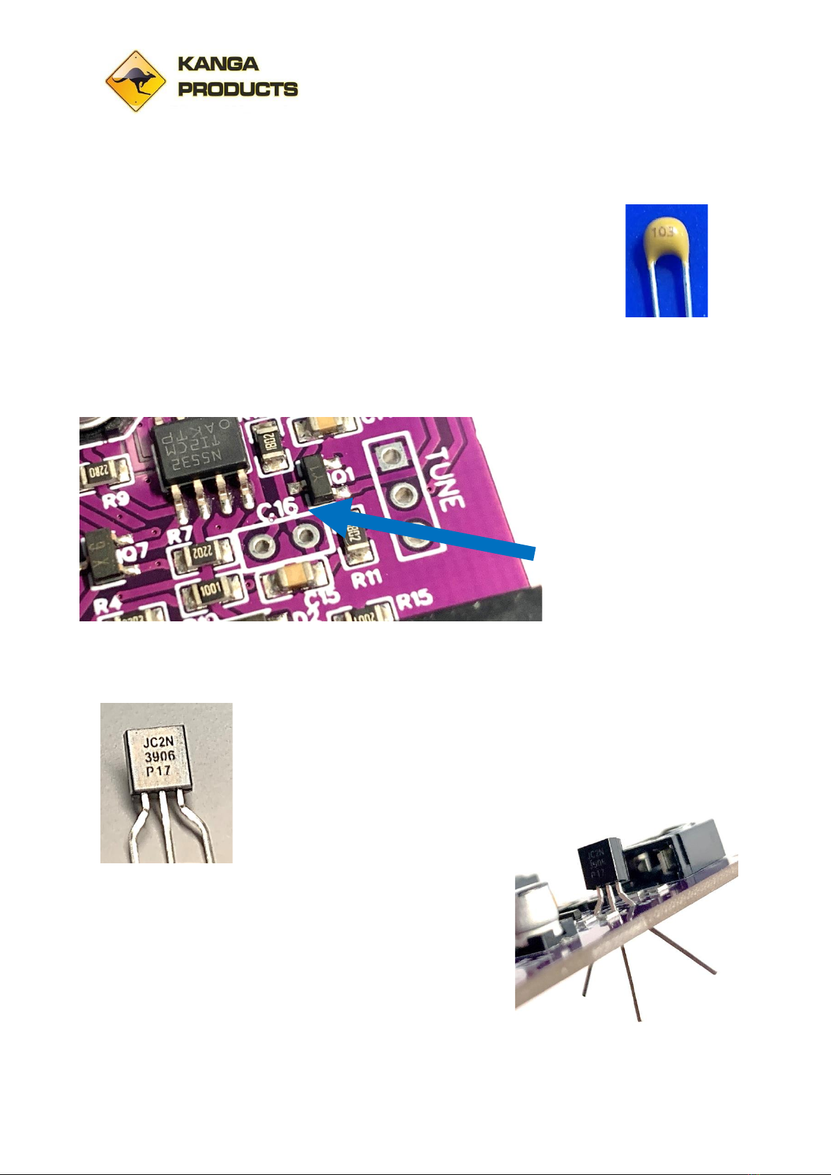
The first part we need to fit is a capacitor C16
C16 is a yellow capacitor with a 2.54mm pin spacing,
The value of this capacitor will adjust the volume of the sidetone, we have
used a value of 0.01uf (10nF) for this. This capacitor controls the sidetone
level, if you find it is too loud you can change this value later, that’s why we have used a
standard capacitor rather than a SMD part. If you want to lower the volume try values
between 1nf and 10nf.
CC16’s position is just
behind the Tune Control
location near the front of
the board.
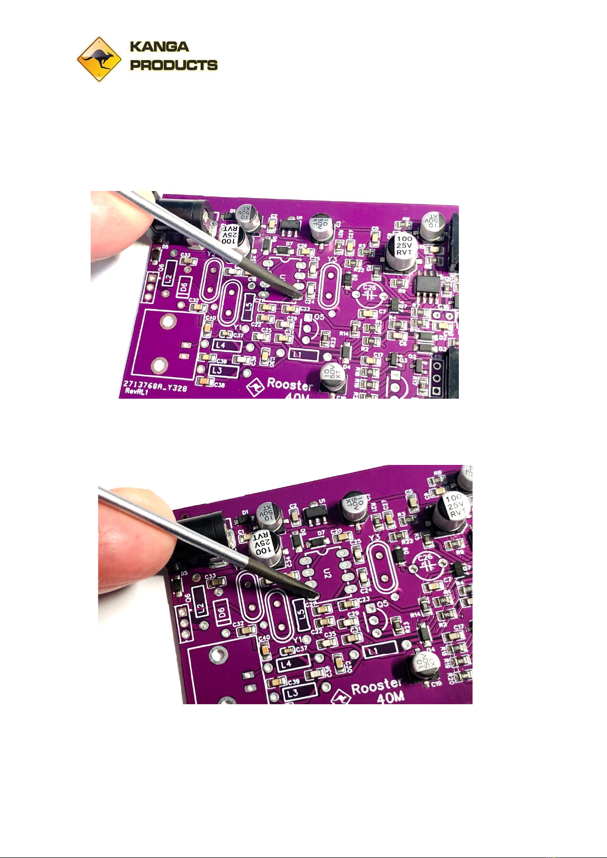
Put this capacitor in its
location and slightly bend
the legs apart under the board, this will stop it falling out when you turn the board over to
solder it. Solder one lead first and re-check it is still sat down correctly on the board. When
happy solder the second leg and trim the leads flush on the board.
The next part is a transistor, IMPORTANT ! many different transistors
all look just the same. Look on the flat side of the transistors in this kit
and check you select the right one for this, you need to find the
2N3906.
This transistor is to be fitted in
position Q4 on the board, it’s just
behind the KEY IN socket. Be careful
not to fit it in the position for the LED!
Make sure you put it the correct way round, the outline on
the PCB shows the way it must be fitted.
Push the part down to the natural stop point, don’t force
it! It will sit about 3mm above the board. Bend the two
outer legs outwards so the part doesn’t fall out when you
turn the board over.

Rooster CW Transceiver Rev6 Page 11 of 33 12/02/2024
Solder the centre pin first and check the alignment of the
transistor it should sit nice and square on the board. When
you’re happy it looks right, solder the other two pins and
trim the leads flush.
Now we can test the sidetone
circuit.
Plug in the headphones and
key.
Next the DC supply.
Tap the key and you should hear the sidetone. IF you wish you can test the muting circuit
too at this time. Perform the ‘Buzz’ test again but while listening to the ‘Buzz’tap the key.
The sidetone should replace the buzz.
Stage 4: Driver and PA Protection Diode
You may want to unplug the chip so you don’t damage it while fitting the remaining parts.
Now fit Q5 transistor, make sure it is the right
one, it should be a 2N4401. Check the printing on
the flat of the transistor. And fit it as you did for
Q4 before.
Make sure it is fitted to match the outline on the
PCB and that it is sat squarely as per the picture
here.

Rooster CW Transceiver Rev6 Page 12 of 33 12/02/2024
We now will fit a protection diode that will help protect the PA from high SWR. This is D6.
Shape this diode ready to fit first.
Bend the leads about 3mm from the body. Take care doing
this. The diode has a glass body and you could break it if
you’re too rough.
You will note that this diode has a black band on one side,
this is VERY important.
The diode must be fitted so that the band is
in line with the line on the symbol on the PCB
for D6.
Stage 5 Mixer
The Rooster uses an active mixer circuit that has much better performance than the old
FOXX3 ever could offer. We need to fit the 8 pin socket for this chip.
The socket, if you look carefully, has
a small notch on one of its shorter
edges. This notch must be next to D7
on the PCB. Make sure that the
socket is flush down on the board. I
solder one pin first and double check
before soldering the other pins.

Rooster CW Transceiver Rev6 Page 13 of 33 12/02/2024
Now it’s time to open the band specific parts bag.
***Important Note***
IF you have the latest batch of PCB’s you will find C29 will not be pre-fitted. This is to allow
the Rooster to be built for LOWER power use. You will receive a standard value capacitor
(100pf for the 40m version or 470pf for the 30m version) with the kit (in the band specific
parts bag) this will give the normal output power levels but if you wish you can fit a lower
value (22pf for 40m or 100pf for 30m) user supplied if you want QRPp power levels.
Fit the C29 (Value as above) capacitor now and trim the leads at the back of the board.
Please don’t be tempted to fit a larger value
capacitor in order to get more power. You will
most likely blow the PA transistor or cause
‘chirp’ on your transmission. The difference
you could achieve would only give you 1dB or
so increase for a lot more risk.
Next, we need to fit the trimmer capacitor. Its colour may not be as shown in the photos
here (if you not reading black and white paper instructions!) a suitable trimmer will be in
the band specific parts bag. Its value will be selected to match the crystals supplied with the
kit (30m or 40m).
Important! The trimmer has one flat
edge, that should be positioned next
to the crystal as shown here. Don’t
worry, you haven’t missed fitting the
crystal, we will do that next
The Crystals.
The supply of crystals has been a little
variable up to now, so I may supply
the crystal pack in a few different
ways.

Rooster CW Transceiver Rev6 Page 14 of 33 12/02/2024
The kit uses three crystals, two in the front-end filter and one for the mixer. The crystals in
your band pack are all the same frequency but some of the characteristics can be different.
Sorry if this stage seems confusing, read it a couple of times to be sure you understand what
you need to do.
The Crystals can be supplied in a few different formats, if all
crystals are the same size any can be used in any position
UNLESS one of them has a coloured top. In that case the
coloured top crystal must be used in the mixer stage.
2) You may get your crystals supplied in two different sizes, if so use the two same size ones
for the front-end filter and the odd one out for this mixer stage.
Whichever format your crystals are supplied in the performance will be the same.
This mixer crystal is to be fitted between the chip socket and the trimmer as shown above.
The Mixer IC
The mixer chip used on the Rooster is getting very rare in its DIP format, but it’s still
available in SMD format.
I have supplied this chip pre-fitted to a small adapter board. This assemble can be treated as
a DIP chip now. Just be sure you check which end is Pin 1 (marked on the adapter board).
CAREFULLY plug the board into the socket on the board.
RF Noise Test
Now again make sure that the chip is plugged in the socket the correct way round.
The adapter board has Pin1, 4, 5, and 8
marked. Make sure Pin 1 is nearest to the DC in
socket.

Rooster CW Transceiver Rev6 Page 15 of 33 12/02/2024
Connect up the headphones/key and power again as before. Now use a metal screw driver
and touch the top pin for the Y2 crystal position. You should hear a mix of Hum and RF
noise, you may even hear some weak CW signals! Don’t forget to remove the leads after this
test!
Stage 6: Fitting the 5 inductors (READ THIS SECTION CAREFULLY!)
The value of the inductors will depend on which band pack you have.
We will break this section down to the two bands. Read this section TWICE BEFORE you fit
anything. Follow the details for the version you have (40m or 30m).
40m Band Instructions
(Only Follow if building the 40m version!)
This stage is the easiest to
make a mistake with so
read and then re-read
this section before you fit
any. There are 5
inductors and
unfortunately most are
very similar in colour
bands.
We need to be 100% sure that the right one is used in the right place.

Rooster CW Transceiver Rev6 Page 16 of 33 12/02/2024
Take time and care with this stage, it is hard to remove parts once fitted.
L1 is a 100uH inductor
The inductors used on this kit use the same colour bands as resistors to identify their value
so you can use the colour resistor code chart that came with the kit to help you.
Please note, these inductors have a dark brown body, the brown strip on the inductors is
lighter in colour and to me looks more coffee colour so take care.
Don’t fit any yet, let’s just check the values.
L1 has bands that are Brown, Black, Brown and the last one is Gold.
L2 is a 10uH inductor
L2 bands are Brown, Black, Black, Silver.
L3 and L4 are both the same value 1uH
L3 and L4 bands are Brown, Black, Gold, Silver
L5 is a 3.3uH inductor
L5 is easy to spot, its bands are Orange, Orange, Gold, Silver.
30m Band Instructions
(Only Follow if building the 30m version!)
This stage is the easiest to
make a mistake with so read
and then re-read this section
before you fit any.
There are 5 inductors and
unfortunately most are very
similar in colour bands.
We need to be 100% sure that the right one is used in the right place.

Rooster CW Transceiver Rev6 Page 17 of 33 12/02/2024
Take time and care with this stage, it is hard to remove parts once fitted.
L1 is a 100uH inductor
The inductors used on this kit use the same colour bands as resistors to identify their value
so you can use the colour resistor code chart that came with the kit to help you.
Please note, these inductors have a dark brown body, the brown strip on the inductors is
lighter in colour and to me looks more coffee colour so take care.
Don’t fit any yet, let’s just check the values.
L1 has bands that are Brown, Black, Brown and the last one is Gold.
L2 is a 6.8uH inductor
L2 bands are Blue, Gray, Gold, Silver.
L3 and L4 are both the same value 0.68uH
L3 and L4 bands are Blue, Gray, Silver.
L5 is a 3.3uH inductor
L5 is easy to spot, its bands are Orange, Orange, Gold, Silver.
Whichever band pack you have take your time to make sure that you follow the instructions
below with care.
Now you know the values read this section again and this
time fit each inductor one by one.
To fit them you will need to bend the leads of each
inductor at 90 degrees right next to the body as shown
here. They will then fit correctly on the board.
Here are the inductors fitted to
the 40m board, of course if
you’re building the 30m
version the some of the
inductors will be different
colours.

Rooster CW Transceiver Rev6 Page 18 of 33 12/02/2024
Make sure yours are fitted flush to the board and that the leads are trimmed flush on the
back of the board.
Stage 7: Front end bandpass filter
We now will fit the last two crystals, Y1 and Y2 that are in your band specific bag
They are both the same and either can be fitted in either position.
When fitted the board
should look like this.
Not much more to do
now.
Stage 8: RIT Control
The RIT tune control.
First remove the nut and washer from the
front of the control, make sure the 3 pins
are not bent over and insert it onto the
board. Push the control down so the body
is flush to the board. It must be flush to
the board or the front panel will not fit!
Solder the centre pin first and check the
control is still positioned correctly, when
happy solder the two outer pins. Trim the
leads flush with the board.

Rooster CW Transceiver Rev6 Page 19 of 33 12/02/2024
Stage 9: Antenna BNC Socket
Now the final part, maybe the hardest to solder!
The Antenna BNC socket
The antenna socket is a heavy item, it is
made from metal and is really a big
heatsink. It can be difficult to solder the
mounting lugs to the PCB if the
soldering iron is not very powerful. You
may need to keep the iron on the lugs
for a prolonged time when soldering so
be very careful that you don’t burn
yourself on the body of it. It will be very
hot for a while after you finish
soldering.
The latest boards have an extra contact hole for
the BNC, this extra hole is there for an alternative
socket arrangement that hasn’t been used on this
version of the Rooster. There is no need to
connect anything to this point. This point is only a
GND connection.
When mounting the BNC make sure that the two
circuit pins pass through the PCB first and solder
these before the two big mounting lugs. Trim
these two leads. Press and hold down the
connector flush to the board and tack solder one
of the lugs. Check it’s flush, if not re-melt the solder again on the lug and reposition. When
happy solder the other lug and then solder the tacked lug fully. Again, be careful this will be
hot for some time afterwards.

Rooster CW Transceiver Rev6 Page 20 of 33 12/02/2024
Stage 10: Testing and Alignment
Time for some testing and alignment. The alignment is the same for either band version,
only the frequency will change.
If you removed the mixer chip earlier for safety now is the time to replace it.
Please understand something important now. This radio is intended to be used in the QRP
area of 40m or 30m. The COA (Centre of Activity) on 40m is 7.030MHz and 10.116Mhz on
30m, you do not need to worry about being bang on these frequencies, there is nothing
magical going to happen if you’re sat on that spot frequency. I have considered swapping
the crystals to be 1 or 2 KHz off the COA to reduce congestion in that area. The crystal
supplied will not give you that much adjustment but if you find yourself a few hundred hertz
off the ‘spot’ don’t worry, be happy!
40m only note now!
I do have crystals that will put your transmission around 7.0293Mhz which work great at
avoiding all the madness on the COA and so result in a better QSO rate. Let me know if you
want one for the mixer (the front end can remain the same for this small change)
30m Note
The 30m Crystal was intended to operate on 10.116Mhz but I find with the supplied crystal I
can set the frequency anywhere between 10.116 and 10.118MHz, the offset at 10.116 isn’t
as great as I would have liked so if you want to be as close to the QRP COA as you can be, try
10.116 first and if your not happy with the offset set the frequency up a few 100Hz, around
10.117 is a good frequency as it still in the QRP area but also next to the FISTS CW Club
frequency (which is 10.118MHz). The exact frequency isn’t that important. I will assume you
have set 10.116MHz for the rest of the instructions but use the frequency you have used in
the following instructions below. Be aware that the further you set the frequency away from
the marked frequency the lower the output power will be. At the extrema limit of
10.118MHz I find my own Rooster is down to 600-700mw of RF power, still a useful level if
you really want to operate at that frequency.
Back to the main testing (either band)
Like all the tests so far, I would recommend a current limited power supply. Up to now you
could expect a max current of 25mA, now you will need to set the limit up a little to 100mA
as we have the driver stage installed and will be testing the transmit chain.
For this test you need another transceiver, antenna, dummy load (advisable), headphones
and key.
Connect the remote transceiver up to a short (1m length) wire will do fine. Since at this
stage we are listening for a very low-level oscillator signal it may be better to drape a wire
from the transceiver’s antenna socket near to the Roosters PCB to be sure to hear its signal.
Table of contents
Other Kanga Products Transceiver manuals
Popular Transceiver manuals by other brands

City Theatrical
City Theatrical SHoW DMX Neo Series Installation and application guide

Maxon
Maxon FM Mobile radio SM-2000 Service manual

Midland
Midland 13-976 owner's guide

Hayward
Hayward HLWLAN owner's manual

3Com
3Com SuperStack II 3C12067 user guide

PS Engineering
PS Engineering PAR100EX System installation and operation manual