ELECRAFT K3 User manual

ELECRAFTK3
HIGH-PERFORMANCE 160 – 6 METER
TRANSCEIVER
K3 KIT ASSEMBLY MANUAL
Rev D, December 26, 2007
Copyright © 2007, Elecraft, Inc.
All Rights Reserved

i
Contents
Introduction...................................................... 1
Customer Service and Support............................1
Technical Assistance.......................................1
Preventing Electrostatic Discharge Damage ... 3
How ESD Damage Occurs..................................3
Preventing ESD Damage.....................................3
Preparing for Assembly................................... 4
Overview of the Kit.............................................4
Tools and Test Equipment Required...................6
Unpacking and Inventory....................................7
Screws.............................................................7
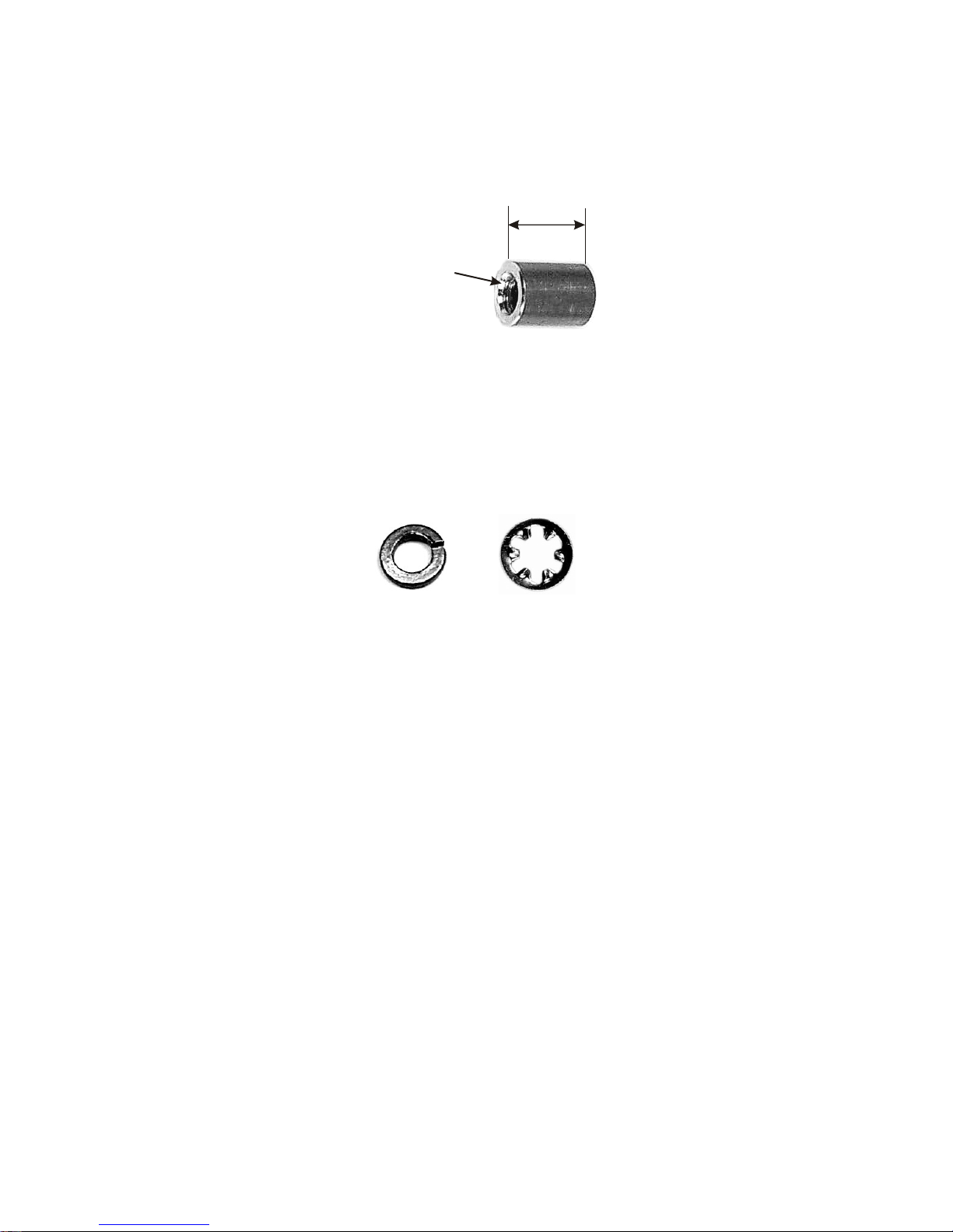
Standoffs .........................................................8
Lock Washers..................................................8
Assembly ......................................................... 9
RF Board and Chassis.......................................10
RF Board Description ...................................10
RF Board and Chassis Assembly Procedure.10
KANT3 or KAT3, Right Side and Rear Panels 18
KANT3 or KAT3 Description.......................18
KANT3 or KAT3, Right Side and Rear Panel
Installation Procedure....................................18
KIO3 Interface ..................................................23
KIO3 Description..........................................23
KIO3 Interface Installation Procedure ..........23
Front Panel and DSP.........................................26
Front Panel and DSP Description..................26
Front Panel Assembly Procedure..................26
Resistance Checks.........................................39
Initial Power On Check.................................40
KREF3 Reference Oscillator.............................40
KREF3 Description.......................................40
KREF3 Installation Procedure ......................40
KSYN3 Synthesizer ..........................................42
KSYN3 Description......................................42
KSYN3 Installation Procedure......................42
Loudspeaker......................................................44
Loudspeaker Description ..............................44
Loudspeaker Installation Procedure..............44
KPA3 Shield......................................................47
KPA3 Shield Description..............................47
KPA3 Shield Installation Procedure .............47
Bottom Cover....................................................49
Bottom Cover Description ............................49
Bottom Cover Hardware Installation ............49
KNB3 Noise Blanker ........................................51
KNB3 Noise Blanker Description.................51
KNB3 Installation .........................................51
Battery BT1.......................................................52
Battery BT1 Description ...............................52
Battery BT1 Installation Procedure ..............52
KBPF3 General Coverage Receive Option ......53
KBPF3 Description....................................... 53
KBPF3 Installation .......................................53
Power Amplifier Jumper Block........................54
Finishing the Enclosure .................................... 54
Fan Opening Cover....................................... 54
Bottom Covers.............................................. 55
Top Cover.....................................................56
Test and Calibration.......................................57
Initial Power Checks......................................... 57
Synthesizer Calibration.....................................58
Filter Setup ....................................................... 58
Reference Oscillator Calibration ......................58
TX Gain Calibration.........................................58
Option Modules................................................58
Enable Modules................................................58
KPA3 100-Watt Amplifier Installation ............58
Other Calibration Procedures ...........................59
Wattmeter Calibration (Optional)..................... 59
S-Meter Calibration (Optional).........................59
Appendix A, Illustrated Parts List................................ A1

1
Introduction
This manual will guide you through assembly of your Elecraft K3 transceiver. We’re confident that you’ll find
the K3 easy to build, even if you’ve had no prior kit-building experience.
Every modern transceiver is complex, and the K3 is no exception. The kit includes nearly 300 individual
components, including over a dozen PC boards and a multi-element modular chassis. But the K3's unique design
eliminates some of the tedious aspects of construction, enabling you to complete assembly in far less time than
previous high-performance transceiver kits. Also, virtually all of the alignment is handled in firmware using the
K3's built-in test capabilities.
If you should you have difficulty, you'll have our full support via phone and e-mail. In addition, we hope you'll
join our growing and enthusiastic community of owner/builders via the Elecraft reflector.
Further information about the Elecraft K3, including specifications, installation, and operation instructions, can
be found in the Owner’s Manual.
Customer Service and Support
Technical Assistance
You can send e-mail to [email protected] and we will respond quickly - typically the same day Monday
through Friday. Telephone assistance is available from 9 A.M. to 5 P.M. Pacific time (weekdays only) at 831-
662-8345. Please use e-mail rather than calling when possible since this gives us a written record of the details
of your problem and allows us to handle a larger number of requests each day.
Repair / Alignment Service (We want to make sure everyone succeeds!)
If necessary, you may return your Elecraft product to us for repair or alignment. (Note: We offer unlimited email
and phone support to get your kit running, so please try that route first as we can usually help you find the
problem quickly.)
IMPORTANT: You must contact Elecraft before mailing your product to obtain authorization for the
return, what address to ship it to and current information on repair fees and turn around times. (Frequently we
can determine the cause of your problem and save you the trouble of shipping it back to us.) Our repair location
is different from our factory location in Aptos. We will give you the address to ship your kit to at the time of
repair authorization. Packages shipped to Aptos without authorization will incur an additional shipping charge
for reshipment from Aptos to our repair depot.

2
Elecraft 1-Year Limited Warranty
This warranty is effective as of the date of first consumer purchase. It covers both our kits and
fully assembled products. For kits, before requesting warranty service, you should fully complete
the assembly, carefully following all instructions in the manual.
What is covered: During the first year after date of purchase (or if shipped from factory, date
product is shipped to customer), Elecraft will replace defective or missing parts free of charge
(post-paid). We will also correct any malfunction to kits or assembled units caused by defective
parts and materials. Purchaser pays inbound shipping to us for warranty repair, we pay shipping to
return the repaired equipment to you by UPS ground service or equivalent to the continental USA
and Canada. Alaska, Hawaii and outside U.S. and Canada actual return shipping cost paid by
owner.
What is not covered: This warranty does not cover correction of kit assembly errors. It also does
not cover misalignment; repair of damage caused by misuse, negligence, or builder modifications;
or any performance malfunctions involving non-Elecraft accessory equipment. The use of acid-
core solder, water-soluble flux solder, or any corrosive or conductive flux or solvent will void this
warranty in its entirety. Also not covered is reimbursement for loss of use, inconvenience,
customer assembly or alignment time, or cost of unauthorized service.
Limitation of incidental or consequential damages: This warranty does not extend to non-
Elecraft equipment or components used in conjunction with our products. Any such repair or
replacement is the responsibility of the customer. Elecraft will not be liable for any special,
indirect, incidental or consequential damages, including but not limited to any loss of business or
profits.

3
Preventing Electrostatic Discharge Damage
There is no climate or work location where the components of your K3 are safe from Electrostatic Discharge
(ESD) unless you take specific steps to prevent such damage. Many of the components in your K3 can be
damaged by static discharges of only a few volts: far too little for you to notice. It is those low-voltage but
destructive discharges that easily happen anywhere and under virtually any environmental conditions.
ESD damage may not be apparent at first. The damaged components may not fail completely. Instead, the
damage may result in below-normal performance for an extended period of time before you experience a total
failure.
How ESD Damage Occurs
Whenever an object containing a static charge touches a circuit in your K3, current will rush into the circuit until
the components reach the same voltage as the source of the static charge. If the voltage or current that passes
through a component in your K3 during that brief period exceeds its normal operating specifications, it may be
damaged or destroyed.
Preventing ESD Damage
ESD damage cannot occur if there is no voltage difference between the components in your K3 and any object
that touches them. That is how anti-static packaging works. Anti-static bags allow the static charge to flow over
their surface, so that any part of the bag that touches the components inside are all at the same potential at all
times. Anti-static foam keeps the leads of sensitive components at the same potential.
At your work bench, avoiding a dangerous voltage is achieved most easily by tying everything together and
connecting them to a common mains safety ground. This includes your K3, individual boards or other sensitive
components as well as everything they may touch at the work table.
Inexpensive static dissipating work mats are readily-available that will steadily and safely drain off any charges
built up on parts or circuit boards placed on them. They are supplied with a lead that connects the mat to the
common workbench ground. Also, metal cabinets on test equipment used on the bench should be tied together
and connected to the common ground.
Most importantly, you must have a way of continuously draining off any static charges that occur on your body.
Such charges are easy to create, even while sitting quietly at the work bench. Moving your feet on the floor,
shifting position in your chair or even moving your arms so that clothing rubs against itself can all produce
destructive static charges. You can discharge yourself by touching an unpainted metal ground, but that will last
only until you move in a way that produces a new static charge. The safest technique is to wear a grounded wrist
strap with a series 1-megohm resistor that continuously drains off any charges. Such wrist straps are readily-
available and inexpensive.
WARNING
DO NOT attach a ground directly to yourself without a current-limiting resistor as this poses
a serious shock hazard. A wrist strap must include a 1-megohm resistor to limit the current
flow. If you choose to touch an unpainted, metal ground to discharge yourself, do it only
when you are not touching any live circuits with your other hand or any part of your body.
We strongly recommend you take the following anti-static precautions (listed in order of importance) to avoid
trouble:
xLeave ESD-sensitive parts in their anti-static packaging until you install them. The packaging may be a
special plastic bag or the component’s leads may be inserted in conductive foam. Parts which are

4
especially ESD-sensitive are identified in the parts list and in the assembly procedures.
xWear a conductive wrist strap with a series 1-megohm resistor. If you do not have a wrist strap, touch a
ground briefly before touching any sensitive parts to discharge your body. Do this frequently while you
are working. You can collect a destructive static charge on your body just sitting at the work bench. DO
NOT attach a ground directly to yourself as this poses a serious shock hazard.
xUse a grounded anti-static mat on your work bench.
xIf you choose to use a soldering iron to work on your K3 for any reason, be sure the iron is ESD-safe
with a grounded tip tied to the same common ground used by your mat or wrist strap.
Preparing for Assembly
Overview of the Kit
The kit comprises two major assemblies: the main chassis and the front panel. Figure 1 shows an assembled
K3/10 with its top cover removed.
The main chassis is literally built up around the RF circuit board, which fills the entire bottom of the unit of the
chassis assembly. Panels are mounted around the RF board using Elecraft’s 2D fasteners. These fasteners allow
individual removal of any one panel, if needed, to gain access to the inside of the radio for servicing. Very few
cables or wires are used in the kit. Most of the other boards and optional accessories plug directly into the RF
board or one of the boards mounted on the RF board.
The front panel assembly, including the display and main operator controls, includes the front panel board and
the digital signal processing (DSP) board.
There are many options that you can add to the basic K3/10, such as the 100 watt amplifier module, internal
antenna tuner, second receiver, additional crystal I.F. filters, etc. If you purchased these options with your K3
kit, you will find instructions to install them at proper places in the assembly procedure to make getting your
complete K3 together and operational in the most efficient manner.

5
FRONT PANEL
ASSEMBLY
(INCLUDING
K3 DSP AND
K3 FRONT PANEL
BOARDS)
K3 DSP BOARD
K3 FRONT PANEL
BOARD (HIDDEN)
KREF3
BOARD
KSYN3
BOARD
K3 MIXER
BOARD
KNB3
BOARD CRYSTAL
FILTERS
(OPTIONAL
8-POLE
FILTERS
SHOWN)
KANT3
OR OPTIONAL
KAT3 BOARD
(KAT3 SHOWN)
K3 LPA
BOARD
KIO3
BOARD
KIO3
REMOTE
I/O MODULE
KIO3 AUDIO
I/O MODULE
AND OPTIONAL
KXV3 MODULE
(HIDDEN)
FRONT
PANEL
SHIELD
K3 RF
BOARD
(FILLS
BOTTOM OF
CHASSIS
ASSEMBLY)
K3 CHASSIS
ASSEMBLY
PA JUMPER
BLOCK
Figure 1. Assembled K3/10 (Less Top Cover).

6
Tools and Test Equipment Required
1. #0 and #1 size Phillips screwdrivers. To avoid damaging screws and nuts, do not use a power
screwdriver. Use the screwdriver that best fits the screw in each step.
2. Soft cloth or other surface to lay cabinet panels on to avoid scratching. A clean static-dissipating mat is
ideal (see below). If using cloth, do not lay circuit boards on it.. See Preventing Electrostatic
Discharge Damage on page 3.
3. Pliers or suitable wrenches for tightening 1/4”, 3/16” and 1/2” nuts. The 1/2” size is used to tighten nuts
on the front panel controls. If available, a deep socket or nut driver is recommended. Pliers or an
ordinary wrench can be used, but requires care to avoid damaging the front panel paint.
4. Long nose pliers.
5. Diagonal cutters.
6. Small rule capable of measuring lengths up to 1” (2.5 cm) with an accuracy of at least 1/16” inch
(1.6 mm).
7. Digital Multimeter (DMM) for resistance checks.
8. RF 50-ohm, 5 W (minimum) dummy load with low VSWR from 160 meters through 6 meters.
9. Power supply 13 VDC nominal (11-16 V) with a cable and Anderson PowerPole®connector. A power
cable kit is provided with your K3 if you do not have a suitable cable with the required Anderson
PowerPole connector. The power supply must be capable of providing at least 3 Amperes for a K3/10
and 20 Amperes for a K3/100. (See Specifications in your Owner’s manual for more information on
power supply recommendations).
The following tools are strongly recommended:
1. ESD wrist strap.
2. Static dissipating work mat.
Optional Equipment:
1. RF Power Meter with accurate readout from 1 mW to 5 watts, minimum.
2. Signal generator with calibrated 50 uV output at 20 or 40 meters.
In addition, two Allen wrenches, 5/64” (2mm) and .050”, are supplied with your kit.

7
Unpacking and Inventory
CAUTION
Do not handle the circuit boards without anti-static protection! Doing so may damage
sensitive components. See Preventing Electrostatic Discharge Damage on page 3 for important
information before proceeding.
Before starting construction, do a complete inventory, comparing the parts in your kit with the parts list in
Appendix A, to familiarize yourself with all of the parts and to ensure the kit is complete. Note that you may
find some extra screws, nuts and washers. A few extras of the more easily lost parts are included on purpose.
All dimensions given in the assembly procedure are provided in both US customary (often called English) and
metric measurements. The native dimensions of the parts are in US Customary units. Approximate metric
equivalents are given to assist those more familiar with that system to identify the correct parts.
Screws
A number of different types and sizes of screws and washers are used in the assembly. It is very important that
you use the screw specified in each location or your finished K3 may not fit together properly. In some places,
using the wrong size screw may damage components. The following various screw types and sizes specified in
the text are shown in Figure 2. Images are shown for comparing relative sizes. They are not to scale. The length
of the screws called for in the text are measured as shown.
2-56 5/32" (4.0 mm) BLACK PAN HEAD
2-56 1/4" (6.4 mm) BLACK PAN HEAD
4-40 3/16" (4.8 mm) BLACK PAN HEAD
4-40 3/16" (4.8 mm)BLACK FLAT HEAD
4-40 1/4" (6.4 mm) BLACK PAN HEAD
4-40 3/8" (9.5 mm) BLACK PAN HEAD
4-40 1/4" (6.4 mm) ZINC PAN HEAD
4-40 3/8" (9.5 mm) BLACK FLAT HEAD
4-40 7/16" (11 mm) ZINC PAN HEAD
4-40 1/2" (13 mm) BLACK FLAT HEAD
6-32 1/2" (13 mm) BLACK PAN HEAD
SCREW AS IDENTIFIED IN TEXT RELATIVE SIZE
(NOT TO SCALE) MEASURING SCREW
LENGTHS
FROM BOTTOM OF
PAN HEAD TO END O
F
THREADED SHAFT
FROM TOP OF FLAT
HEAD TO END OF
THREADED SHAFT
Figure 2. Screw Sizes Used in Assembly.

8
Standoffs
A number of threaded standoffs are used. As with the screws and washers, be sure you use the correct size as
specified in the text. Standoff lengths are measured from end to end as shown in Figure 3. Standoffs threaded for
2-56 and 4-40 screws are used.
LENGTH AS SPECIFIED IN TEX
T
THREAD SIZE AS
SPECIFIED IN TEXT,
EITHER 4-40 OR 2-56
Figure 3. Typical Standoff.
Lock Washers
Two types of lock washers are used in the K3 (see Figure 4). It is important that you use only the type specified
and put the washers exactly where indicated. Failing to use the correct type may result in short circuits to nearby
circuit traces. Adding washers or placing the washers in the wrong position may cause parts to fail to fit together
properly.
SPLIT INSIDE TOOT
H
Figure 4. Lock Washers.

9
Assembly IMPORTANT ASSEMBLY INFORMATION
1. A variety of screws and fasteners are used to assemble your K3:
xUse your rule to check the length of screws and standoffs before installing them. Some
components are only 1/16” different from others but using the wrong size may result in parts not
fitting correctly, possibly damage electrical and mechanical components. See Screws on page 7
and Standoffs on page 8 for more measurement instructions.
xLoosen screws as needed for a proper fit. When mounting parts with multiple screws or
adjacent parts that fit together, such as the exterior cabinet panels, loosen adjacent mounting
screws as needed to adjust the parts for the best fit. Be certain you re-tighten the screws before
proceeding!
xEnsure all screws are tight. A loose screw can cause both mechanical and electrical problems
such as intermittent operation, unexpected noise or false signals (birdies) in the receiver.
xThreads can be easily stripped if too much force is applied when tightening screws. Use the
correct size hand tool and apply only moderate torque. Do not use a power screwdriver!
2. Brief circuit descriptions are provided through the manual for those interested in the functions of the
circuits. For more detailed circuit information, consult the Theory of Operation in your Owner’s
manual.
CAUTION – TO AVOID DEGRADING THE PERFORMANCE OF YOUR K3:
DO NOT DISTURB ANY ADJUSTMENTS ON THE BOARDS!
Each board was tested and aligned for optimum performance at the factory. Any change to
these adjustments will degrade the performance of your K3 or prevent its operation
altogether. All user calibrations and adjustments are done in firmware using the front panel
menus. These are described at the appropriate points in the assembly procedures.
DO NOT ADJUST THE TURNS ON ANY TOROIDS!
The position of the turns on the cores of many toroids has been adjusted at the factory to
produce exactly the inductance needed for the circuit to work properly. Any attempt to
adjust their position or to make a coil look “nicer” may seriously degrade circuit
performance.
Also, do not attempt to fix the turns or coils in place with adhesives or other materials.
Adding material to the coils on the factory-aligned and tested boards will alter their
inductance, again degrading circuit performance.
ESD SENSITIVE!
Observe ESD precautions when handling the circuit boards and whenever you are working
on your K3 with the covers off. Failure to observe ESD precautions may result in your K3
not operating at all, or operating but not meeting normal factory performance
specifications due to damaged components. See page 3 for more information.

10
RF Board and Chassis
RF Board Description
The RF PCB (Printed Circuit Board) is the heart of the K3 transceiver, both physically and electrically. During
assembly, it serves as an attachment point for other PCBs as well as chassis panels, acting as the glue that holds
things together. During operation, the RF board provides signal routing to and from all modules. For more
information, see Theory of Operation, RF Board, in the K3 Owner’s Manual.
RF Board and Chassis Assembly Procedure
Remove the RF board from its anti-static packaging. The top side of the board is the side with the toroid
inductors and relays along with other components, including several connectors along one edge. The edge with
the connectors is the back edge of the board, while the front edge has notches cut in it that will fit around front
panel controls. Locate the six rectangular bare copper pads for the 2D fasteners (see Figure 5). There is one in
each corner of the board and one in the center of each side (see Figure 11 on page 14).
ESD SENSITIVE!
WEAR A GROUNDED
WRIST STRAP OR TOUCH
AN UNPAINTED METAL GROUND
BEFORE HANDLING THE RF BOARD.
TYPICAL 2D FASTENER
LOCATION
Figure 5. 2D Fastener Location on RF Board.
Install 2D fasteners at the six spaces provided (one at each corner and at the center of each side of the RF
board). Mount the fasteners on the bottom side of the board as shown in Figure 6. Be sure the 2D fasteners are
oriented so the side of each fastener lines up with the edge of the RF board as shown.
WIDE SHOULDER ON 2D
TOWARD EDGE
4-40 SPLIT LOCK WASHERS
4-40 3/16" (4.8 mm) BLACK
PAN HEAD SCREWS
2D ON THE
BOTTOM OF
BOARD
SIDE FLUSH
WITH EDGE
Figure 6. Installing 2D Fasteners on RF Board.

11
Install a 4-40 3/8” (9.5 mm) standoff on the RF board near connector Z1 as shown in Figure 7 below and
Figure 11 on page 14. This standoff will support the mixer to be installed later. Install the standoff using three
lock washers as shown below with two of the lock washers between the standoff and the RF board.
ESD SENSITIVE!
CONNECTOR
Z1
TOP OF RF BOARD
4-40 3/8" (9.5 mm)
STANDOFF
TWO 4-40 SPLIT
LOCK WASHERS
4-40 SPLIT
LOCK WASHER
4-40 1/4" (6.4mm)
ZINC PAN HEAD
SCREW
Figure 7. K3 Mixer Standoff Location.
Install the two KBPF3 standoffs shown in Figure 8. Even if you didn’t purchase the KBPF3 general
coverage option, the standoffs and hardware are included in the K3 kit to make installing the option easier at
some future date. Note that these standoffs have only one lock washer between each standoff and the RF board.
TOP OF RF BOARD 4-40 1/2" (13 mm) STANDOFF
4-40 SPLIT LOCK WASHER
4-40 1/4" (6.4mm) ZINC PAN HEAD SCREW
ESD SENSITIVE!
LEFT SIDE OF RF BOARD
Figure 8. Installing KBPF3 Standoffs.

12
Install hardware to attach Q3 to the RF board near the rear left corner as shown in Figure 9 and Figure 11
on page 14.
#4 INSIDE TOOTH
LOCK WASHER 4-40 NUT
CIRCUIT
BOARD
Q3
4-40 7/16" (11 mm)
ZINC PAN HEAD SCREW RF BOARD LEFT REAR CORNER
Figure 9. Installing Q3 Hardware on RF Board.
Locate the crystal I.F. filters. Two types of filters are available: standard 5-pole filters and optional 8-pole
filters (see Figure 10). One standard 5-pole 2.7 kHz filter is supplied. If you have elected to equip your K3 with
the optional 8-pole 2.8 kHz filter, it has been supplied instead of the 2.7 kHz filter. If you have purchased
additional filters, they may be installed now as well. If you plan to add filters later, spaces may be left for them.
For example, if you plan to add the FM or a 6 kHz AM filter later, you can leave spaces FL1 and FL2 open for
them and install the 2.8 kHz filter in position FL3. The filters are not hard to move about later, so if you aren’t
sure, install the widest at FL1, the next widest at FL2 and so on.
See Appendix A in your Owner’s Manual for more information about making a filter
plan and installing multiple filters and for installing filters for use with the sub-receiver.
Enter the following data on Table 1.You will need this information to set up your filters after assembling
your K3. Be sure you’re following the rule described in the step above about the proper order for the filters.
Enter the bandwidth in the row opposite the filter position where it will be installed.
Enter the FREQ OFFSET shown on each filter. The optional 8-pole filters have no offset
marked on them. Enter a zero in the FREQ OFFSET column for those filters. Note that the
frequency offset may be negative, indicated by a minus sign (single dash)ahead of the
number! Turn the VFO A knob to the left (anti-clockwise) to enter negative values.
Table 1. Filters Installed.
POSITION BANDWIDTH FREQ OFFSET
FL1
FL2
FL3
FL4
FL5

13
Install the filters as shown in Figure 10. Refer to the list of filters you created in Table 1 to determine which
filter to install at each location.
CAUTION
1) Do not use screws longer than 1/4” (6.4 mm) to mount the filters. Use your ruler to
measure the screws before installing them. Longer screws may extend into the optional 8-
pole filter and destroy it. We strongly recommend you use a 1/4” screw even when installing
the 5-pole filters to reduce the possibility of damaging an 8-pole filter should you change
them later.
2) Do not over-tighten the screws. Too much torque may pull the threaded bushing out of
the bottom of the filter module.
4-40 1/4" (6.4 mm)
ZINC PAN HEAD
SCREW
#4 INSIDE
TOOTH
WASHER
STANDARD 5-POLE FILTERS OPTIONAL 8-POLE FILTERS
RF BOARD, TOP SIDE.
FILTERS MUST BE INSTALLED IN
CORRECT POSITIONS. SEE TEXT
FOR DETAILS.
Figure 10. Installing Crystal I.F. Filters on RF Board.

14
ESD SENSITIVE!
WEAR A GROUNDED
WRIST STRAP OR TOUCH
AN UNPAINTED METAL GROUND
BEFORE HANDLING THE RF BOARD.
2D
FASTENER
2D
FASTENER 2D
FASTENER
2D
FASTENER
2D
FASTENER
2D
FASTENER
MIXER
STANDOFF
CRYSTAL
I.F. FILTER
Q3
KBPF3
STANDOFFS
PA JUMPER BLOCK
(PREINSTALLED)
Figure 11. RF Board Partially Assembled.

15
Install the Low Power Amplifier (LPA) board in the cutout on the RF board as shown in Figure 12. The
LPA board is held in place by its connectors until the bottom cover is installed..
ESD SENSITIVE! POSITION THE
LPA BOARD SO
THE THREE
CONNECTORS
MATE PROPERLY.
TOP VIEW
SUPPORT EACH
CONNECTOR FROM
BENEATH WHILE PRESSING
THEM TOGETHER. WORK
AROUND THE CONNECTORS
PRESSING THEM TOGETHER
IN INCREMENTS UNTIL
ALL THREE ARE
FULLY MATED.
DO NOT DISTURB THE
POSITION OF THE THREE
POWER TRANSISTORS.
THEY WILL BE SECURED
TO THE STANDOFFS LATER.
BOTTOM VIEW
LPA CONNECTOR
1
2
Figure 12. Installing the Low Power Amplifier (LPA).

16
Mount the front panel shield on the RF board as shown in Figure 13, then mount a 2D fastener on each ear
at the top of the shield as shown. Be sure the 2D fasteners are oriented with the widest part between the two
holes and the edge toward the outside as shown.
4-40 1/4" (6.4mm) PAN HEAD ZINC SCREW 4-40 SPLIT LOCK
WASHER
4-40 1/4" (6.4mm) ROUND
STANDOFF
RF PC BOARD
NOTE! NO WASHER BETWEEN
PC BOARD AND STANDOFF
4-40 3/16" (4.8mm) BLACK PAN HEAD SCREWS
4-40 SPLIT LOCK WASHERS
2D FASTENERS WITH WIDEST SHOULDER
TOWARD THE OUTSIDE AS SHOWN
Figure 13. Installing Front Panel Shield.
Mount the K3 mixer board on the RF board as shown in Figure 14. The mixer plugs into Z1 on the RF
board.
CIRCUIT
BOARD
4-40 1/4" (6.4 mm) ZINC
PAN HEAD SCREW
#4 SPLIT LOCK
WASHER
STANDOFF
ON RF BOARD
MIXER
ESD SENSITIVE!
FRONT PANEL
SHIELD
Figure 14. Installing K3 Mixer Board.

17
Locate the two side panels. They are approximately 4” (10 cm) by 9-7/8” (25 cm) in size. Both panels have
six counter-sunk screw holes near the edges. Note that the countersunk holes are farther from one end than the
other. This is important. You will need to orient the panels correctly as you install them. The side panels are
different as well. In addition to the six counter-sunk screw holes, the left side panel has two holes near the
centerline for attaching the handle. The left side panel with the handle attached is shown in Figure 16. The right
side panel has six additional holes, four for mounting the side feet and two for attaching other parts inside the
K3 (see Figure 19). Set the right side panel aside for now.
Check the inside (partially painted) of both panels to ensure no masking tape is covering any screw holes. If
found, peel it off.
Attach the handle to the left side cover using the hardware shown in Figure 15 at each end. The ribbed side
of the handle faces away from the panel. Tighten the screws enough to compress the lock washers, but do not
tighten the screws so much that you deform the handle end cover. The handle should move easily to allow room
for your fingers between the handle and cover for carrying, then lie flat against the cover when it is not in use.
6-32 1/2" (1.3cm) BLACK PAN HEAD SCREW
HANDLE END COVER
FLEXIBLE HANDLE WITH SPRING STEEL
INSERT
K3 SIDE COVER
#6 SPLIT LOCK WASHER
6-32 NUT
Figure 15. Installing Side Handle Mounting Hardware.
Attach the left side panel to the RF board assembly as shown in Figure 16 using five 4-40 3/16” (17mm)
black flat head screws. Do not use washers. When the panel is oriented correctly, the edge of the panel will
extend about 1/2” (13 mm) past the 2D fasteners at the front panel shield. If the threaded holes in the 2D
fasteners don’t line up properly with the holes in the side panels, temporarily loosen the screws attaching the 2D
fastener to the RF board or front panel shield, then tighten them again after the side panel is installed.
USE 4-40, 3/16" (4.8 mm) BLACK FLAT HEAD SCREWS TO
ATTACH THE SIDE PANEL WHERE INDICATED BY THE ARROWS.
THIS END OF THE PANEL EXTENDS ABOUT 1/2" (1.3 cm)
PAST THE 2D FASTENERS
Figure 16. Mounting Left Side Panel.

18
Inspect the area where the side panel meets the front panel shield, and make sure there is positive
mechanical contact at the screw just below the end of the handle and about 3/4” (19 mm) above the RF board.
The area of the side panel around that point is clean metal. Tighten the screws as needed to ensure good contact
at that point and at each 2D fastener.
CAUTION
Failure to establish a solid contact at that point may result in birdies in the receiver.
Throughout the assembly, be sure all chassis screws are tight!
Mount a 2D fastener at the top back corner of the left side panel (the one you just installed) with a 4-40
3/16” (4.8 mm) black flat head screw as shown in Figure 17. Do not use washers. Be sure the 2D fastener is
oriented correctly as shown in the figure.
4-40 3/16" (4.8 mm
)
BLACK FLAT
HEAD SCREW
WIDEST SIDE OF
2D FASTENER
CLOSEST TO
SIDE PANEL
Figure 17. Installing Left Side Panel 2D Fastener.
KANT3 or KAT3, Right Side and Rear Panels
If you purchased a KAT3 with your kit, you did not get a KANT3 board with your kit.
For more information, see the KANT3 AND KAT3 Circuit Description below.
KANT3 or KAT3 Description
The basic K3/10 includes a KANT3 antenna input module. If you’ve ordered a KAT3 antenna tuner, the
KANT3 is not required and will not be supplied with the kit. In either case, the module plugs into the RF board
at the back-right corner. Both the KANT3 and KAT3 provide antenna surge protection, as well as resistors for
bleeding off static DC charge. The KAT3 provides a wide-range, switchable C-in/C-out L-network. See Theory
of Operation, KANT3 and KAT3, in the K3 Owner’s Manual for more details.
KANT3 or KAT3, Right Side and Rear Panel Installation Procedure
Locate the rear panel and check the inside for any masking tape still covering screw holes. If found, peel it
off.
Mount the SO239 connector in the ANT1 position on the rear panel using two 4-40 1/4” (6.4 mm) black
pan head screws, two 4-40 inside tooth lock washers and two 4-40 nuts as shown in Figure 18. The flange of the
SO239 connector is on the inside (unpainted) side of the rear panel.
4-40 1/4" (6.4mm)
BLACK PAN HEA
D
SCREWS
4-40 INSIDE TOOTH
LOCK WASHERS
AND NUTS
Figure 18. Mounting the ANT1 Connector.
Other manuals for K3
27
Table of contents
Other ELECRAFT Transceiver manuals

ELECRAFT
ELECRAFT K3 User manual

ELECRAFT
ELECRAFT KBPF3 User manual

ELECRAFT
ELECRAFT K2 User manual

ELECRAFT
ELECRAFT K3 User manual

ELECRAFT
ELECRAFT K144XV Owner's manual

ELECRAFT
ELECRAFT KPA3 User manual

ELECRAFT
ELECRAFT KX3 User manual

ELECRAFT
ELECRAFT KX3 Operating instructions

ELECRAFT
ELECRAFT K4 User manual

ELECRAFT
ELECRAFT K1 User manual

ELECRAFT
ELECRAFT KX2 User manual

ELECRAFT
ELECRAFT KX2 User manual

ELECRAFT
ELECRAFT K3 User manual

ELECRAFT
ELECRAFT KNB2 User manual

ELECRAFT
ELECRAFT K2 User manual

ELECRAFT
ELECRAFT K3 User manual

ELECRAFT
ELECRAFT K3 User manual

ELECRAFT
ELECRAFT K2 Reference guide

ELECRAFT
ELECRAFT K4 Reference manual

ELECRAFT
ELECRAFT K3EXREF Owner's manual