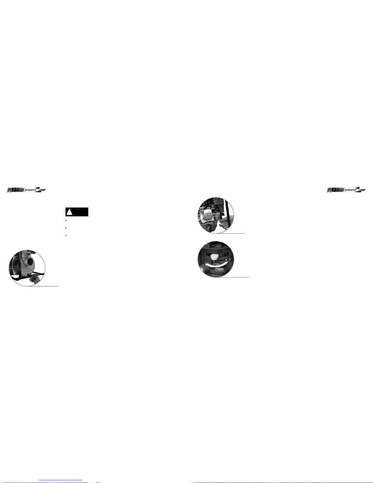
Release the start handle gently instead of suddenly to protect
the starter from being damaged.
!CAUTION
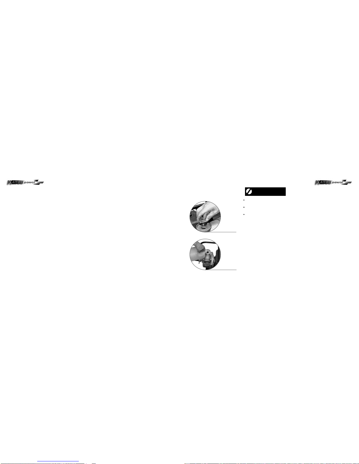
Starting up in high altitude regions
In high altitude places, standard carburetor produces a dense mix of fuel and
air, resulting in decreases in the engine performance and increased fuel
consumption. To keep the engine with high performance, install a carburetor
main spray nozzle and readjust the idle speed screw.
Contact your dealer for replacing the carburetor and to make adjustments in
advance. Even with a proper nozzle modification on the engine, the engine
power output will decrease about 3.5% with each 305m over sea level.
Opera t i n g i n s t r u c t i o n s
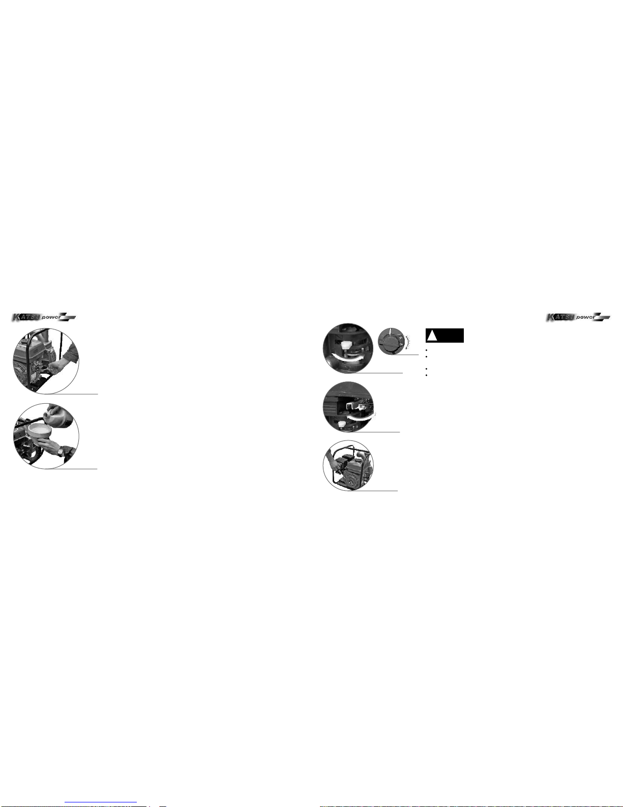
Start and warm up the engine, and then close the choke gradually.
Set the throttle valve in accordance with specified rational speed.
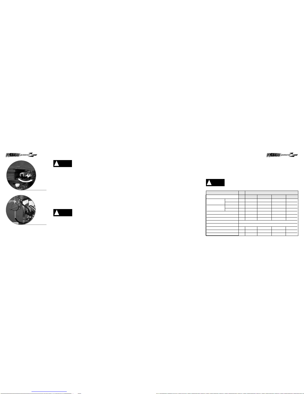
Stopping
Move throttle handle to the extreme right end.
Set the engine switch to OFF.
1
2
1
2
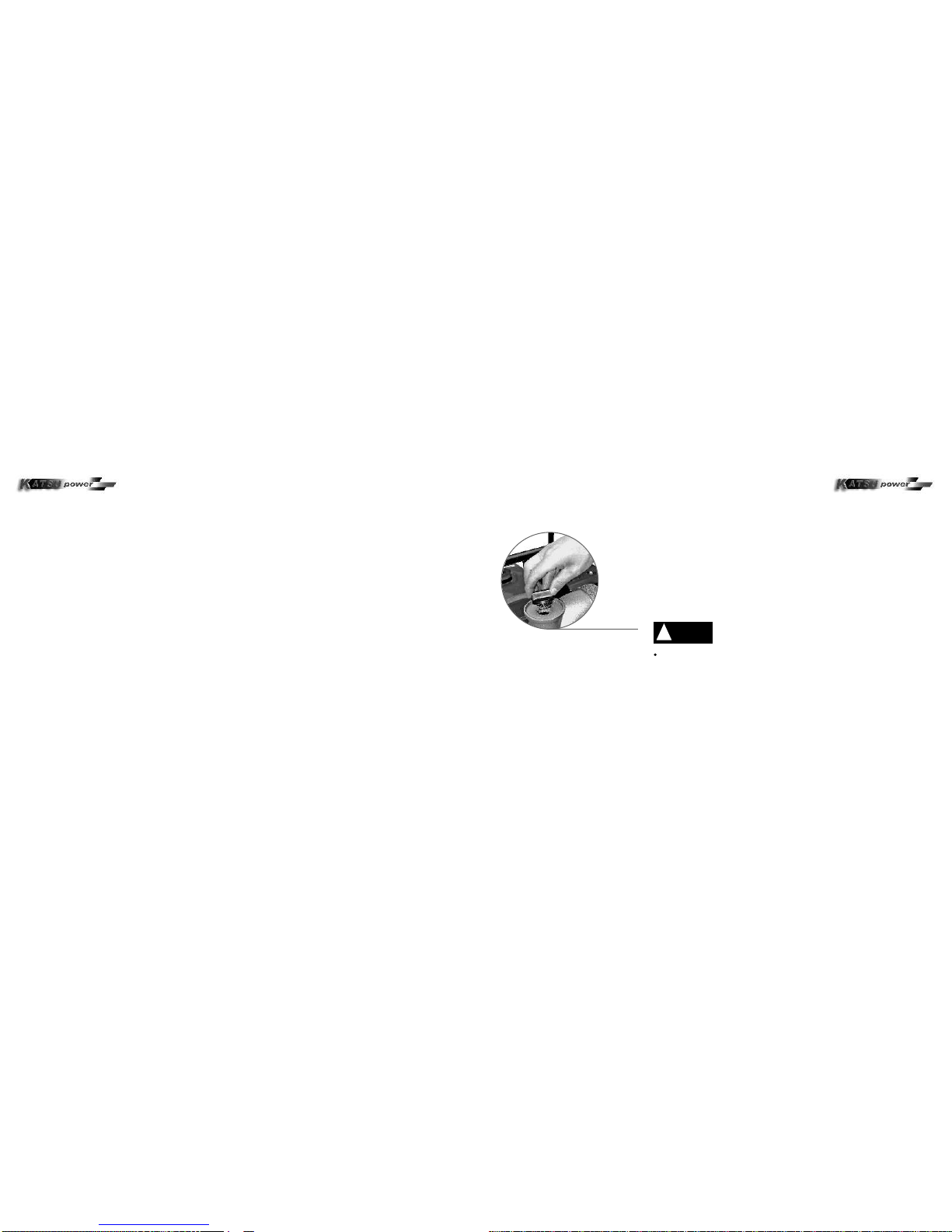
Once a carburetor was changed to used in high altitud places.
Operation at lower altitudes may cause serious engine damage
!CAUTION
12
Set the engine switch to OFF
Move the throttle valve to the right
+
Before maintenance and service, turn off the engine. If the engine should
run, make sure that the engine is in a well-ventilated area. Exhaust
emissions from the engine contains toxic carbon monoxide (CO2), which
may cause loss of consciousness and even life.
Only use genuine KATSU POWER parts and specified
maintenance tools or the water pump may be damaged.
!CAUTION
17
NOTE
(1) Use in extremely dusty area, the job
should be done more often.
(2) Should be done by your dealer, unless
you are equipped with proper repair tools,
and are proper trained and are qualified
mechanically.
FRECUENCY EACH WHICHEVER COMES FIRST
TIME ITEMS
OIL LEVEL O
OIL CHANGE O
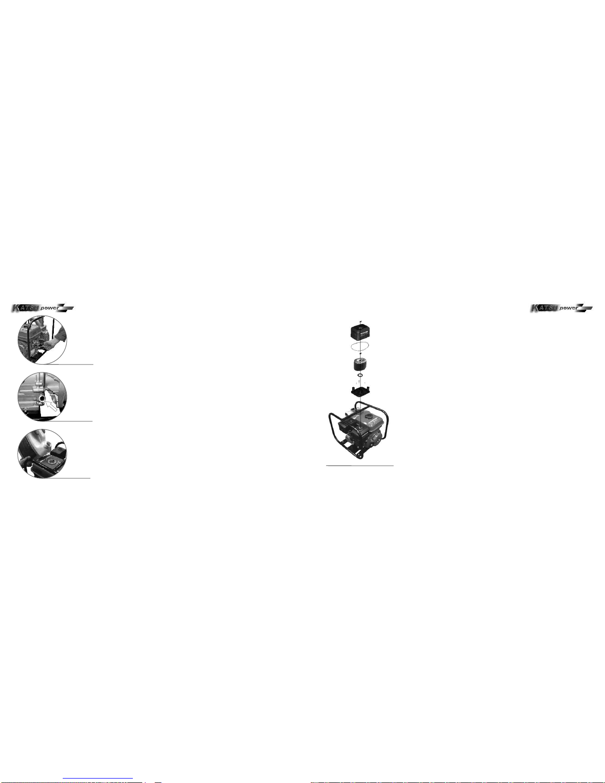
AIR CLEANER CHECK O
CHANGE O(2)
EVERY 100 HOURS RUNNING-LEAN
EVERY TWO YEAR REPLACE O(2)
O(2)
SPARK PLUG
VALVE CLEARANCE ADJUSTMENT
CLEAN COMBUSTION CHAMBER
SPARK ELIMINATOR
FUEL SUPPLY PIPE
IMPELLER CHECK
WATER PUMP TANK COVER
WATER INLET VALVE CHECK O(2)
FIRST MONTH
OR 20 HOURS EVERY 3 MONTH
OR 50 HOURS EVERY 6 MONTH
OR 100 HOURS EVERY YEAR
OR 300 HOURS
ENGINE OIL CHECK O
O(1)
O(1)
OWNER MANUAL DCA KAT S U P O W E R WAT E R P U M P S OWNER MANUAL DCA KAT S U P O W E R WAT E R P U M P S