KBS InoxAir VRBEC2400 User manual

BEDIENUNGSANLEITUNG
KBS Gastrotechnik GmbH – Schoßbergstraße 26 – 65201 Wiesbaden
www.kbs-gastrotechnik.de
Stand November 2022

VRBEC
Assembly Instruction Flexible Abluftbox • Multi Purpose Cubic Box • Boîtier souple
d‘évacuation d‘air • Ventilator de exhaustare constructie exibila
• Pазностороний вытяжной вентилятор • Flexibele afzuigven-
tilator • Prilagodljiv odvodni ventilator • Višenamjenski odsisni
ventilator • Elszívó ventilátor, exibilis elhelyezés • Flexibilná
odvetrávacia jednotka • Caja de extracción de aire exible • Uni-
wersalny wentylator wywiewny MPC • Fleksibel udsugningsluft-
box • Flexibilní odtahový box • Joustava poistoilmalaite
Spannung • Voltage • Tension • Tensiune • Напряжение •
Spanning • Napetost • Napon • Feszültség • Napätie •
Tensão • Voltaje • Napięcie • Spænding • Napětí • Jännite
Frequenz • Frequency • Fréquence • Frecventa • Частота • Frequentie •
Frekvenca • Frekvencija • Frekvencia • Frekvencia • Frequência •
Frecuencia • Częstotliwość • Frekvens • Frekvence • Taajuus
Leistungsaufnahme • Power consumption • Puissance consommée •
Consum de putere • Потребление мощности • Stroomverbruik •
Vhodna moč • Snaga • Teljesítményfelvétel • Príkon • Potencia absorvida •
Potencia absorbida • Pobór mocy • Optagen effekt • Příkon • Ottoteho
Stromaufnahme • Current • Consommation de courant • Consum de curent •
Потребление токa • Stroom • Električni tok • Jakost struje • Áram •
Odber prúdu • Corrente • Corriente eléctrica requerida •
Pobór prądu • Strømforbrug • Příjem proudu • Virrankulutus
Max. Stromaufnahme • Max. current consumption • Consommation électrique max. •
Consum max curent • Макс. потребляемый ток • Max. opgenomen stroom • Maks.
sprejem toka • Maks. uzimanje struje • Maximális áramfelvétel • Maximálna spotreba
prúdu • Consumo máximo de corrente • Corriente eléctrica requerida • Maksymalny
prąd pobierany • Maks. strømforbrug • Max. Příjem proudu • Enimm. virrankulutus
Max. Umgebungstemp. • Max. ambient temp. • Temp. ambiante max. • Temp. ambianta
maxima • Максимальная температура окружающей среды •
Max. omgevingstemp. •
Max. temp. okolice • Max. temperatura
•
Max. környezeti hőmérséklet
• max. okolitá teplota
• Max temp.ambiente • Temperatura ambiental máx. • Maks. temperatura otoczenia •
Maks. omgivelsestemp. • Max. Teplota okolí • Enimm. ympäristön lämpötila
Max. Fördermitteltemp. • Max. medium temp. • Temp. de fonctionnement maximal •
Temperatura ambientala max • Макс. температура среды •
Max. omgevingstemperatu-
ur.
•
Max. temp. zraka • Maks. temp. Prostora
•
Max. környezeti hőmérséklet
• -Maximalna
Teplota Media • Máxima temperatura media • Máxima temperatura media •
Maks. temp. substancji transportowanej • Maks. transportmiddeltemp. • Max. Teplota
podpůrných prostředků • Enimm. kuljetettavan aineen lämp.
Baugröße • Size • Dimension • Marime • Размер • Formaat • Velicinia •
Velicina gradevine • Méret • Rozmer • Tamanho • Dimensiones constructivas •
Wielkość • Konstruktionsstørrelse • Stavební velikost • Rakennekoko
Schaltschema • Wiring Diagram • Schéma de câblage • Schema de conecatre •
Схема подключения • Aansluitdiagram • Vezalna shema • Shema spajanja •
Bekötési rajz • Schéma zapojenia • Esquema eléctrico • Esquema de conexiones
eléctricas • Schemat połączeń • Strømskema • Schéma zapojení • Kytkentäkaavio
ID Uf P I Imax tAtM
[V] [Hz] [W] [A] [A] [°C] [°C] [mm]
VRBEC2400 143077 230V~ 50 687 3,05 3,2 40 120 500 149253
VRBEC3000 143078 230V~ 50 840 3,7 3,9 40 120 500 149253
VRBEC2900 143079 230V~ 50 1016 4,47 4,7 60 120 500 149253
VRBEC4600 149264 230V ~ 50 1408 9,43 9,9 50 120 500 149253
VRBEC6000 149321 230V ~ 50 1500 10,22 10,7 50 120 700 149253
VRBEC6300 149327 230V ~ 50 1248 8,38 8,8 50 120 700 149253
VRBEC7600 149331 230V ~ 50 1238 8,37 8,8 50 120 700 149253
Drehzahlregelung über 0-10V DC Eingang
Speed control over 0-10V DC input
Pегулирование скорости вращения - вход 0-10B DC
Änderungen vorbehalten • Modication reserved • Sous réserve de modications • Sub rezerva modicarilor • Компания оставляет за собой право вносить изменения без предварительного уведомления.
• Wijzigingen voorbehouden • Pridržujemo si pravico do sprememb. • Zadržano pravo izmjena • Változtatások joga fenntartva • Zmeny sú vyhradené • Modicação reservada • Reservado el derecho de
modicaciones • Zmiany zastrzeżone • Med forbehold for ændringer• Změny vyhrazeny • Oikeus muutoksiin pidätetään
Alfred-Zingler-Straße 36
45881 Gelsenkirchen
info@inoxair.de
www.inoxair.de
Tel.
Fax
.
+49 209 386 20 200
+49 209 386 20 299
InoxAir®

Daten gemäß ErP Richtlinie laut EU-Verordnung 327/2011
Data in accordance with ErP Directive 327/2011 of the European Parliament
Gerätetyp
Units / Model
VRBEC2400
VRBEC3000
VRBEC2900
VRBEC4600
VRBEC6000
VRBEC6300
VRBEC7600
ID-Nummer
ID-number 143077 143078 143079 149264 149321 149327 149331
ErP-Konform
ErP-conformity 2015 2015 2015 2015 2015 2015 2015
Gesamtefzienz
Overall efciency
ηes [%] 63,2 63,1 57,1 66,73 66 68,3 65,7
Messkategorie
Measurement category
A A A A A A A
Efzienzkategorie
Efciency category
statisch
static
statisch
static
statisch
static
statisch
static
statisch
static
statisch
static
statisch
static
Efzienzgrad am Energieefzienzoptimum
Efciency grade at optimum energy efciency point N75,5 74,3 66,9 75,7 74,5 77,4 74,8
Drehzahlregelung
Variable speed drive
integriert
integrated
integriert
integrated
integriert
integrated
integriert
integrated
integriert
integrated
integriert
integrated
integriert
integrated
Herstellungsjahr
Year of manufacture
siehe Typenschild
see nameplate
Amtliche Registriernummer
Commercial registration number
Niederlassungsort des Herstellers
Site of manufacturer
InoxAir GmbH, Deutschland
InoxAir GmbH, Germany
Nennmotoreingangsleistung am Energieefzienzoptimum
Nominal motor power input at optimum energy efciency point
Pe[kW] 680 0,87 1,16 1,4 1,56 1,36 1,37
Volumenstrom am Energieefzienzoptimum
Volumetric ow at optimum energy efciency point qV[m³/h] 1673 2073 2613 3303 4024 4668 5318
Statischer Druck am Energieefzienzoptimum
Static pressure at optimum energy efciency point psf [Pa] 904 937 882 1000 904 709 600
Umdrehungen pro Minute am Energieefzienzoptimum
Rotations per minute at the optimum energy efciency point n [1/min] 4020 3645 3184 3184 2548 2000 1641
Spezisches Verhältnis
The specic ratio
Spezisches Verhältnis liegt nahe bei 1 und deutlich unter 1,11.
The specic ratio is close to 1 and signicantly below 1.11.
Informationen zur Demontage, Recycling und Entsorgung
Information on dismantling, recycling and disposal
Bitte beachten Sie die Bedienungsanleitung des Produktes.
Observe the user manual of this product.
Optimale Lebensdauer
Optimal life
Bitte beachten Sie die Bedienungsanleitung des Produktes.
Observe the user manual of this product.
Beschreibung weiterer bei der Ermittlung der Energieefzienz
von Ventilatoren genutzter Gegenstände wie Rohrleitungen,
die nicht in der Messkategorie beschrieben und nicht mit dem
Ventilator geliefert werden.
Description of additional items used when determining the
fan energy efciency, such as ducts, that are not described
in the measurement category and not supplied with the fan.
Für die Ermittlung der Energieefzienz wurden keine besonderen Gegenstände außer
den gemäß der Messkategorie verlangten Anschlusskomponenten eingesetzt.
No special items have been used for determining the fan energy efciency, except the
required connection components according to the measurement category.
*
**
***
Nicht ErP-konform, kann nur als Ersatzgerät für identische Ventilatoren gemäß ErP-Verordnung 327/2011 oder außerhalb der E.U. verkauft werden. /
Not ErP compliant, can be sold only as a spare part for identical fans dened by the regulation (EC) 327/2011 or outside the E.C..
ErP-konform gemäß EU-Verordnung 327/2011, da die Leistungsaufnahme am Energieefzienzoptimum < 125W ist. /
Compliant to the ErP-regulation (EC) 327/2011, the power consumption at optimum efciency is < 125W.
ErP-konform gemäß EU-Verordnung 327/2011, da die maximale Leistungsaufnahme der Dunstabzugshaube < 280W ist. /
Compliant to the ErP-regulation (EC) 327/2011, the maximum power consumption of the kitchen hood is < 280W.
Alfred-Zingler-Straße 36
45881 Gelsenkirchen
info@inoxair.de
www.inoxair.de
Tel.
Fax
.
+49 209 386 20 200
+49 209 386 20 299
InoxAir®

Arbeitsanweisung:
Anschluss des RAE‐EC Reglers an einen EC‐Ventilatormotor mit den Stromlaufplan Nr.
149253.
Ist folgendes Anschlussschema zu beachten:

5 –stufiger Geschwindigkeitsregler Code RAE-EC
BETRIEBSANLEITUNG
Warnungen:
xVor der Installation und Inbetriebnahme des Gerätes bitte diese Anleitung sorgfältig durchlesen um einen
korrekten Gebrauch zu gewährleisten.
xVor dem Einbau und dem Einstecken des Reglers in das Netz ist zu prüfen, ob die in dieser Anleitung erläu-
terten technischen Merkmale auch denen des elektrischen Netzes und der Spannung entsprechen.
xVerwenden Sie stets qualitativ hochwertige und angemessene Elektrodenkabel, um den Regler an das
Stromnetz und an die Spannung anzuschließen.
xDie elektrischen Geräte sind regelmäßig zu kontrollieren: Beschädigte Leitungen und Kabel sind sofort zu
ersetzen.
xEs wird empfohlen, dass Sie innerhalb des Reglers die<ĂďĞůůćŶŐĞ kurzhalten, um den Kontakt mit denje-
nigen Bauteilen zu vermeiden, die sehr hohe Temperaturen erreichen können.
xInstallieren Sie den Regler an belüfteten Orten und nicht in der Nähe von Wärmequellen, besonders dann
wenn die Strombelastung in der Nähe der Höchstleistung liegt.
xUm Feuergefahr, Stromschlag oder andere Störungen zu vermeiden, sollte der Regler nicht Regen oder
Feuchtigkeit ausgesetzt werden und die Anlage sollte an einem trockenen Ort aufgestellt werden
xEs wird empfohlen, den Regler nicht in Bereichen mit Feuchtigkeit, Dämpfen oder Gasen zu installieren
und die direkte Sonneneinstrahlung oder Wärme- und Kältequellen zu vermeiden.
xDer Regler ist nur in Übereinstimmung mit den hier genannten Anweisungen zu installieren und zu ver-
wenden: Der Hersteller ist nicht verantwortlich für die unsachgemäße Verwendung (falls das Gerät für
andere Anwendungen benutzt wird als die, für die er entworfen wurde) oder für den Fall, dass diese Be-
triebsanleitung und ihre Hinweise nicht beachtet werden.
xDas Gerät darf nicht auf einem vibrierenden Untergrund montiert werden.
xDer Regler sollte nur an einem Ort installiert werden, an dem er ungestört arbeitet, aber gleichzeitig leicht
zugänglich ist.
xDer Regler ist für die vertikale Installation ausgelegt.
xNachdem die Abdeckung zur Befestigung an der Halterung entfern wurde, verbinden Sie die Kabel mit der
Klemmleiste auf der Platine gemäß dem Anschlussplan. Anschließend die Abdeckung wieder sorgfältig
schließen.
Der Hersteller erklärt hiermit, dass das Produkt frei von Herstellungsfehlern ist.
Die Garane besteht für 12 Monate, wenn das Produkt korrekt verwendet wird.
Der Hersteller behält sich das Recht vor, ohne vorherige Ankündigung Änderungen an dem Gerät oder den
Unterlagen vorzunehmen, um z.B. ihre Leistungen zu verbessern.
Der Hersteller haet nicht für Schäden, die durch Missbrauch, unsachgemäße Verwendung, inkorrekter
Nutzung oder als Folge von unbefugten Reparaturen/Änderungen verursacht wurden.
TECHNISCHE EIGENSCHAFTEN
xStromversorgung: 10 Vdc (+ 10%).
xMax. ƵƐŐĂŶŐƐƐƉĂŶŶƵŶŐ 0 ... 10 V: 0,1mA
xMax. SĐŚĂůƚůĞŝƐƚƵŶŐƵƐŐĂŶŐƐƌĞůĂŝƐ: 230V- 50Hz Max.1A
xIP-Schutz: IP55
xŶǁĞŶĚƵŶŐƐƉŽƐŝƚŝŽŶ: vertikal
xGröße: 128x108x73 mm.
xGewicht: 0.200 kg.
xUmgebungstemperaturbereich: -20 ... .60 ° C
xBetriebstemperaturbereich für Lagerung: -20 ... .70 ° C
xDĂdžƌ&ϴϱйŶŝĐŚƚŬŽŶĚĞŶƐŝĞƌƚ
xSteckverbinder max. Leiterquerschnitt: 1,5mm²
ANSCHLUSSDIAGRAMM UND FUNKTION
Ausgangsspannung über Frontknopf gewählt:
Posion 0 = 0 V Posion 3 = 6 V
Posion 1 = 2 V Posion 4 = 8 V
Posion 2 = 4 V Posion 5 = 10 V
Trimmer "OFFSET" (P1)
Die Ausgangsspannung kann mit Trimmer "OFFSET" reduziert werden P1:
xWerkseinstellung: keine Reduzierung (Trimmer- Zeiger in Richtung Symbol "+" drehen)
xMaximale Ausgangsspannungsredukon: ca. 25% (Trimmer- Zeiger in Richtung Symbol "-" drehen)
Jumper "SPEED 5" (J1)
Mit dem Jumper "SPEED 5" (J1) kann ausgewählt werden, ob die vom Trimmer "OFFSET" (P1) erreichte Ausgangsspannungsredukon auch bei der Drehzahl 5 wirksam ist oder nicht.
xJumper J1 in Position "OFSET" (Werkseinstellung): Die Trimmer "OFFSET" Einstellung ist bei den ^ƚƵĨĞŶ 1-5 wirksam.
xJumper J1 in Stellung "+ 10V": Die Trimmer "OFFSET" Einstellung ist bei ^ƚƵĨĞŶ 1-4 wirksam, ^ƚƵĨĞ 5 Ausgangsspannung = 10Vdc fest.
Jumper "LED" (J2)
Mit dem Jumper "LED" (J2) kann ausgewählt werden, ob die Beleuchtung der LED über den Frontknopf oder durch einen externen Kontakt gesteuert werden soll.
xJumper J2 auf Position "INT": Frontknopf auf Position "0", LED = AUS; Frontknopf auf Position "1-5", LED = EIN.
xJumper J2 auf Position "EXT": Wenn der externe Kontakt mit den Klemmen "LED" und "GND" (Stecker CN2) geschlossen ist, leuchtet die LED. Wenn der externe Kontakt mit den An-
schlüssen "LED" und "GND" (Stecker CN ") ŽĨĨĞŶ ist, ist die LED ausgeschaltet.
Die Led kann extern durch einen mechanischen Kontakt oder auch durch einen offenen Kollektor gesteuert werden.
WŽƚĞŶƚŝĂůĨƌĞŝĞƌ<ŽŶƚĂŬƚĨƺƌĞdžƚĞƌŶĞ'ĞƌćƚĞ
Der Regler kann ĞŝŶĞŶƉŽƚĞŶƚŝĂůĨƌĞŝĞŶ<ŽŶƚĂŬƚ steuern, indem er mit dem Stecker "EXTERNAL" (CN3) und in Serie auf eine 24Vac-230Vac-Spannung (diese muss extern zugeführt
werden)angeschlossen wird.
Hinweis: Die Venlbetägung ist nicht mechanisch, sondern "im festen Zustand" (durch Thyristor), also ohne Kontakt schaltende Funken (dies könnte ein Problem sein, wenn
brennbares Gas beteiligt ist).
00 02/2019
ĞdžƚĞƌŶĞ'ĞƌćƚĞ
ŝŶƐƚĞůůƵŶŐĚĞƌƵƐŐĂŶŐƐƐƉĂŶŶƵŶŐ
>ŝƐƚĂŶǁĞŶŶ^ƉĞĞĚϭďŝƐϱ
ĚƵƌĐŚĚĞŶ&ƌŽŶƚŬŶŽƉĨŐĞǁćŚůƚ
ǁŝƌĚ
el
mit der
d
er
sorgfältig
ät
oder d
en
n
n
n
ekt
er
T
rim
m
OF
FSE
E
E
E
E
E
E
E
E
T"T"
T"
T"
T"
T"
T"
T
T"
T
T
Ein
n
Ein
Ein
n
Ein
Ei
Ein
E
in
Ein
in
n
n
ste
ste
s
st
ste
st
s
ste
st
ste
te
t
s
u
ng
ist
be
be
e
e
e
b
be
be
e
e
e
e
e
i
i
i
i
i
^ƚƵ
ƚƵ
^ƚƵ
^ƚƵ
^ƚ
^ƚƵ
ƚƵ
Ƶ
ĨĞŶ
ĨĞŶ
Ĩ
ĞŶ
ĨĞŶ
ĨĞŶ
ĨĞŶ
ĨĞŶ
ĨĞŶ
ĨĞŶ
ĨĞŶ
ĨĞŶ
Ĩ
1
1
1
1
1
1
1
1
1
-
4 w
n,
ob
die
Bel
euc
uc
uc
uc
uc
c
uc
u
htu
h
n
ng
n
n
n
n
n
n
n
n
n
n
der LED über de
n F
ti
on "0", LED
= A
A
A
A
= A
= A
U
U
US;
U
U
U
U
U
U
U
U
U
U
U
U
U
U
Fr
Fr
Fr
Fr
Fr
Fr
F
ont
knopf auf Po
sit
rn
e
Ko
Ko
Ko
Kon
Kon
tak
ak
ak
t
mit
t
t
t
t
den
d
d
Kle
mm
mm
mme
mm
mm
m
m
m
m
m
m
m
m
m
n
"LED"
und
)
ŽĨĨ
ĞŶ
ist
is
is
, i
i
i
s
s
st
die
die
e
di
LED
L
L
au
au
au
sge
sc
h
alt
alt
alt
et.
han
ischen
Kon
ta
ta
tak
t
ode
r a
a
a
uch
u
du
du
dur
ch
ein
n
n
e
en
e
ŶĞ
'Ğƌ
ƌ
ƌ
Ğƌ
Ğƌ
ƌ
ƌ
ƌ
ƌ
ƌ
ƌ
ćƚĞ
ćƚ
ćƚ
ćƚ
ć
ć
ć
ćƚ
ć
ć
ƚ
ŝĂů
ĨƌĞ
Ğ
Ğ
ŝĞ
ŝĞ
ŝĞŶ
<ŽŶƚĂ
Ŭƚ
ste
ste
ste
ste
ste
ste
s
s
te
te
te
e
uer
u
u
u
u
u
n, ind
em
em
m
er
mit
t
t
d
de
d
d
ird
.
be
tägung ist
nic
c
c
c
ht
h
h
h
h
h
h
h
h
h
h
mec
han
han
han
han
h
ha
ha
h
h
h
h
h
h
isc
h,
,
son
so
so
so
so
s
s
s
s
o
o
o
der
er
er
n
bet
eiligt is
t).
Kontakt für externe Geräte
Der Regler kann einen Kontakt steuern, indem er mit dem Stecker „EXTERNAL“ (CN3) und in Serie auf eine 24Vac-230Vac-Spannung (diese muss extern zugeführt werden)
angeschlossen wird.

Five Speed Motor Regulator code RAE-EC
OPERATING INSTRUCTIONS
Warnings:
xBefore installaon and start-up, read this manual carefully to ensure correct use.
xBefore installing and plugging the regulator into the mains, check that technical characteriscs explained
in this manual correspond to those of the electrical mains system and loads.
xAlways use high quality and suitable secon electric cable wire to connect the regulator to the mains and
loads.
xInspect electrical equipment regularly: immediately replace damaged lines and cables.
xWe recommend that you keep the cable length short inside the regulator to avoid contact with compo-
nents that can reach high temperatures.
xInstall the regulator in venlated places and away from sources of heat, especially if the current load ab-
sorpon is close to the maximum.
xTo avoid danger of fire, electric shock or malfuncons, do not expose the regulator to rain, humidity, fa-
voring the installaon in a dry place. It is recommended to not install the regulator in areas with moisture,
fumes or gas. Avoid direct sunlight or heat/cold sources.
xThe regulator must be installed and used only in compliance with the instrucons provided: the manufac-
turer won’t be responsible for the improper use of it (if it is used for applicaons different than those for
which it was designed) or for failure to comply with these warnings.
xDo not mount the device on vibrang base.
xThe regulator should be installed in a locaon where it works undisturbed and can easily be reached.
xThe regulator is designed for vercal installaon.
xRemove the cover for mounng to the support and connecng cables to the terminal block on the board
according to the connecon diagram. Then close it again carefully.
The manufacturer declares that this product is free from manufacturing defects.
The guarantee lasts 12 months if the product is used correctly.
The manufacturer reserves the right to make changes without noce, of the regulator or of the documen-
taon in order to improve its performances.
The manufacturer does not accept liability for damage caused by misuse, incorrect use, improper use or
as a consequence of unauthorized repairs or modificaons.
TECHNICAL CHARACTERISTICS
xPower supply: 10 Vdc (+10%).
xMax. load output 0...10 V: 0,1mA
xMax. load external switching contact: 230Vac– 50Hz Max.1A
xIP protecon: IP55
xUse posion: vercal
xSize: 128x108x73 mm.
xWeight: 0.200 kg.
xOperaon ambient temperature range: -20….60°C
xOperaon temperature range for storage: -20….70°C
xOperaon relave humidity: 85% non-condensaon
xConnectors max wire cross secon: 1,5mm2
CONNECTION DIAGRAM AND FUNCTION
Output voltage selected by means of front knob:
Posion 0 = 0 V Posion 3 = 6 V
Posion 1 = 2 V Posion 4 = 8 V
Posion 2 = 4 V Posion 5 = 10 V
Trimmer “OFFSET” (P1)
The output voltage can be reduced with trimmer “OFFSET” P1:
xFactory seng: no reducon (trimmer cursor rotated towards symbol “+”)
xMaximum output voltage reducon: approximately 25% (trimmer cursor rotated towards symbol “-”)
Jumper “SPEED 5” (J1)
By means of jumper “SPEED 5” (J1) it is possible to select whether the output voltage reducon achieved by the trimmer “OFFSET” (P1) is also effecve on speed 5 or not.
xJumper J1 in posion “OFSET” (factory seng): trimmer “OFFSET” seng is effecve on speeds 1-5.
xJumper J1 in posion “+10V”: trimmer “OFFSET” seng is effecve on speeds 1-4, speed 5 output voltage = 10Vdc fixed.
Jumper “LED” (J2)
By means of jumper “LED” (J2) it is possible to select whether lighng of the LED is controlled by the front knob or by an external contact.
xJumper J2 on posion “INT”: front knob on posion “0”, LED=OFF; front knob on posion “1-5”, LED=ON.
xJumper J2 on posion “EXT”: when external contact connected to terminals “LED” and “GND” (connector CN2) is closed, LED is ON; when external contact connected to terminals
“LED” and “GND” (connector CN”) is opened, LED is OFF.
The Led can be externally controlled by a mechanical contact or also by an open collector signal.
External switch contact
The regulator can control an external switch contact by connecng the laer to connector “EXTERNAL” (CN3) and in series to a 24Vac-230Vac voltage (to be supplied externally).
NoƟce: The contact actuaon is not mechanical but “solid-state” (by thyristor), therefore without contact switching generated sparks (which could be an issue where flammable gas is
involved).
00 02/2019
he
documen-
s
e,
imp
mp
mp
mp
mp
rop
op
op
op
er
use
e
e
or
ut
pu
T
”
se
e
ng
ng
ng
ng
ng
n
ng
ng
n
ng
i
ffe
cv
e o
e
e
e o
e
e
e
e
o
e
n s
n s
n s
n s
n
s
n
n s
n
n
s
pee
pee
pee
pee
peepee
pee
pee
pee
ds
d
d
d
d
d
d
d
d
e
the
r lighng
of
of
of
of
of
o
of
of
of
the LED is contro
lle
on
“
0”,
LED
=OF
OF
OF
OF
O
OF
O
O
O
F;
fr
r
r
ro
r
ro
r
ro
r
r
r
nt knob on posi
on
c
ont
act co
nne
e
e
cte
cte
cte
d
d
d
d
d t
d
d
d
d
d
o
o t
t
t
t
o
o
erminals
“
LED
”
an
ed
, L
L
L
L
ED
ED
ED
ED
is
is
is
is
OFF.
mec
han
ica
a
a
l
lc
c
l c
l
l
l
l
on
on
ont
act
t
t
or
o
o
o
al
so
o
o
by
an
ope
pe
pe
n c
o
e
rna
a
ls
ls
ls
ls
l s
witch
con
on
on
on
on
on
n
n
n
tac
ta
ta
ta
ta
t
ta
ta
a
t by conn
ec
ec
ec
ng
the
e
e
e
la
on is
not
t
t
t
t
t
t
t
t
t
me
cha
a
a
a
a
a
a
a
a
a
nic
nic
nic
nic
ni
nic
nic
nic
ni
i
c
al
a
a
a
a
a
a
but
“
sol
id
d
-
sta
sta
sta
sta
sta
sta
sta
sta
sta
t
a
a
te
t
t
t
”

EG – Einbauerklärung
nach Richtlinie Maschine (2006/42/EG)
Der Hersteller InoxAir GmbH
Alfred-Zingler-Str. 36
D-45881 Gelsenkirchen
Tel.: +49 (0)209 386 20 200
erklärt hiermit, dass folgende Produkte:
Produktbezeichnung: Flexible Abluftbox
Typenbezeichnung:
ELQ, MPC, MPC...TW, MPS, MPS...F
den grundlegenden Anforderungen der Richtlinie Maschinen
(2006/42/EG) entsprechen: Anhang I, Artikel 1.1.2, 1.1.3,
1.1.5, 1.2.1, 1.3.1, 1.3.2, 1.3.4. und 1.5.1.
Die unvollständige Maschine entspricht weiterhin allen
Bestimmungen der Richtlinien Elektrische Betriebsmit-
tel (2006/95/EG) und Elektromagnetische Verträglichkeit
(2004/108/EG).
Die unvollständige Maschine darf erst dann in Betrieb genom-
men werden, wenn festgestellt wurde, dass die Maschine,
in die die unvollständige Maschine eingebaut werden soll,
den Bestimmungen der Richtlinie Maschinen (2006/42/EG)
entspricht.
Folgende harmonisierte Normen wurden angewandt:
DIN EN 12100 Sicherheit von Maschinen - allgemeine Ge-
staltungsleitsätze - Risikobeurteilung und Risikomin-
derung (ISO 12100:2010)
DIN EN 60204-1 Sicherheit von Maschinen - Elektrische
Ausrüstungen von Maschinen, Teil 1: Allgemeine
Anforderungen.
Der Hersteller verpichtet sich, die speziellen Unterlagen zur
unvollständigen Maschine einzelstaatlichen Stellen auf Ver-
langen elektronisch zu übermitteln.
Die zur Maschine gehörenden speziellen technischen Unter-
lagen nach Anhang VII Teil B wurden erstellt.
Montage
Montagearbeiten dürfen nur von Fachpersonal unter
Beach-tung der Montageanleitung und den gültigen
Vorschriften und Normen ausgeführt werden. Die oben
genannten Sicherheits-hinweise sind einzuhalten! Trennen
Sie immer das Gerät allpolig vom Netz, bevor Sie das
Produkt montieren bzw. Ste-cker anschließen oder ziehen.
Sichern Sie das Gerät gegen Wiedereinschalten!
Die Verbindung mit der Ansaugseite erfolgt bauseits
mittels flexiblen Verbindungsstutzen oder Bundkragen. Die
Ausblas-öffnung, die sowohl stirnseitig als auch seitlich
erfolgen kann, wird ebenfalls bauseits ausgeführt. Die
Kabelausführung und das eventuelle Anbringen eines
Ausblasstutzens erfolgt bauseits. Anstatt eines
Ausblasstutzens kann auch ein Sei-tenteil entfernt werden.
Fundamente müssen eben, nivelliert und von den Abmaßen
für die MPC Abluftbox geeignet sein. Verlegen Sie die
Kabel und Leitungen so, dass diese nicht beschädigt
werden und niemand darüber stolpern kann. Nach dem
Einbau dürfen keine bewegliche Teile mehr zugänglich
sein! Die Elektroanschlüsse am Gerät sind gemäß dem
Schaltbild anzuschließen! Stellen Sie vor der Inbetriebnahme
sicher, dass alle Dichtungen und Verschlüsse der Steckver-
bindungen korrekt eingebaut und unbeschädigt sind, um zu
verhindern, dass Flüssigkeiten und Fremdkörper in das Pro-
dukt eindringen können. Hinweisschilder dürfen nicht verän-
dert oder entfernt werden! Betreiben Sie den Ventilator immer
in der richtigen Luftströmungsrichtung (s. Markierung auf dem
Gerät)! Der Einbau ist zur Wartung und Reinigung gut zu-
gänglich und mit geringem Aufwand ausbaubar auszuführen!
Für die Versionen mit herausgeführtem Thermokontakt gilt:
Bei nicht angeschlossenem / abgefragten Thermokontakt er-
lischt der Garantieanspruch. Schäden aufgrund Überhitzung
können nicht berücksichtigt werden.
Betriebsbedingungen
ruck Ventilatoren nicht in explosionsfähiger Atmosphäre be-
treiben! Die maximale Umgebungstemperatur auf dem Typen-
schild ist zu beachten! Überprüfen Sie ob die Anschlussspan-
nung den Angaben auf dem Typenschild entspricht!
Wartung
ruck Ventilatoren sind mit Ausnahme von empfohlenen Rei-
nigungsintervallen wartungsfrei. Stellen Sie sicher, dass keine
Leitungsverbindungen, Anschlüsse und Bauteile gelöst wer-
den, solange das Gerät nicht allpolig vom Netz getrennt ist.
Sichern Sie die Anlage gegen Wiedereinschalten! Es dürfen
keine einzelnen Bauteile gegeneinander ausgetauscht wer-
den. D.h. dass z.B. die für ein Produkt vorgesehenen Bauteile
nicht für andere Produkte verwendet werden dürfen! Staub-
haltige Luft ergibt mit der Zeit Ablagerungen im Laufrad und
Gehäuse. Dies führt zu Leistungsreduzierung und Unwucht
des Ventilators und so zu einer Verringerung der Lebensdau-
er! Laufrad mit Pinsel / Bürste / Tuch reinigen. Achtung! Aus-
wuchtmassen nicht entfernen oder verschieben! Innenraum
keinesfalls mit Wasser oder gar Hochdruckreiniger reinigen!
Durch Einbau eines Luftlters k ann d as Reinigungsintervall
erheblich verlängert bzw. vermieden werden!
Entsorgung
Das achtlose Entsorgen des Gerätes kann zu Umweltver-
schmutzungen führen. Entsorgen Sie das Gerät daher nach
den nationalen Bestimmungen Ihres Landes.
EG Konformitätserklärung
Im Sinne der EG – Richtlinie
Elektromagnetische Verträglichkeit EMV
– Richtlinie 2004/108/EG
Der Hersteller InoxAir GmbH
Alfred-Zingler-Str. 36
D-45881 Gelsenkirchen
Tel.: +49 (0)209 386 20 200
erklärt hiermit, dass die nachfolgend bezeichneten, unvoll-
ständigen Maschinen in ihrer Konzipierung und Bauart sowie
in der von uns in Verkehr gebrachten Ausführung den Bestim-
mungen der genannten EG-Richtlinien entsprechen. Bei einer
mit uns nicht abgestimmten Änderung der unvollständigen
Maschinen verliert diese Erklärung ihre Gültigkeit.
Produktbezeichnung: Flexible Abluftbox
Typenbezeichnung:
ELQ, MPC, MPC...TW, MPS, MPS...F
Folgende harmonisierte Normen wurden angewandt:
DIN EN 61000-6-2 Elektromagnetische Verträglichkeit
(EMV)- Teil 6-2: Fachgrundnormen Störfestigkeit für
Industriebereich.
DIN EN 61000-6-3 Elektromagnetische Verträglichkeit
(EMV) - Teil 6-3: Fachgrundnormen Fachgrundnorm
Störaussendung für Wohnbereich, Geschäfts- und
Gewerbebereiche sowie Kleinbetriebe.
Verantwortlich für diese Erklärungen ist:
InoxAir GmbH
Alfred-Zingler-Str .36
D-45881 Gelsenkirchen
Diese Montageanleitung enthält wichtige Informationen, um
ruck Ventilatoren sicher und sachgerecht zu montieren,
zu transportieren, in Betrieb zu nehmen, zu warten und zu
demontieren. Das Gerät wurde gemäß den allgemein aner-
kannten Regeln der Technik hergestellt. Trotzdem besteht
die Gefahr von Personen- und Sachschäden, wenn Sie die
folgenden Sicherheits- und Warnhinweise in dieser Anleitung
nicht beachten.
Die Produkte dürfen nur in Betrieb genommen werden,
wenn zuvor die Montageanleitung sowie die Sicherheits-
vorschriften gelesen und verstanden wurden. Bewahren
Sie die Anleitung so auf, dass sie jederzeit für alle Benut-
zer zugänglich ist. Geben Sie das Gerät an Dritte stets
zusammen mit der Montageanleitung weiter.
ruck Ventilatoren unterliegen einer ständigen Qualitätskon-
trolle und entsprechen den geltenden Vorschriften zum Zeit-
punkt der Auslieferung. Da die Produkte ständig weiterentwi-
ckelt werden, behalten wir uns das Recht vor, jederzeit und
ohne vorherige Ankündigung, Änderungen an den Produkten
vorzunehmen. Wir übernehmen keine Gewähr für die Richtig-
keit oder Vollständigkeit dieser Montageanleitung.
Die Gewährleistung gilt ausschließlich für die ausge-
lieferte Konguration! Wir s chließen G arantie, Gewähr-
leistungs- und Haftungsansprüche bei Personen- und
Sachschäden durch fehlerhafter Montage, bestimmungs-
widriger Verwendung und/oder unsachgemäßer Handha-
bung aus.
Sicherheitshinweise
ruck Ventilatoren sind im Sinne der EU-Maschinenrichtlinie
2006/42/EG eine Komponente (Teilmaschine). Das Gerät
ist keine verwendungsfertige Maschine im Sinne der EU-
Maschinenrichtlinie. Es ist ausschließlich dazu bestimmt, in
Maschinen bzw. lufttechnische Geräte und Anlagen eingebaut
oder mit anderen Komponenten zu einer Maschine bzw. Anla-
ge zusammengefügt zu werden. Das Gerät darf erst in Betrieb
genommen werden, wenn es in die Maschine / die Anlage, für
die es bestimmt ist, eingebaut ist und diese die Anforderungen
der EU-Maschinenrichtlinie vollständig erfüllt. Verwenden Sie
ruck Ventilatoren nur in technisch einwandfreiem Zustand!
Prüfen Sie das Produkt auf offensichtliche Mängel, wie bei-
spielsweise Risse im Gehäuse oder fehlende Nieten, Schrau-
ben, Abdeckkappen oder sonstige anwendungsrelevante
Mängel! Verwenden Sie das Produkt ausschließlich in dem
Leistungsbereich, welcher in den technischen Daten sowie
auf dem Typenschild angegeben ist! Berührungs-, Ansaug-
schutz und Sicherheitsabstände sind gemäß DIN EN 13857
vorzusehen. (Durch Schutzgitter oder ausreichend lange
Rohrleitungen.) Allgemein vorgeschriebene elektrische und
mechanische Schutzeinrichtungen sind bauseits vorzusehen!
Der elektrische Anschluss sowie Reparaturen dürfen nur von
Elektrofachkräften vorgenommen werden! Bei sämtlichen In-
stallations- und Wartungsarbeiten muss der Stromkreis unter-
brochen werden! Die Bedienung des Gerätes durch Personen
mit eingeschränkten physischen, sensorischen oder mentalen
Fähigkeiten, darf nur unter Aufsicht oder nach Anleitung von
verantwortlichen Personen erfolgen. Kinder sind von dem
Gerät fernzuhalten!
Transport und Lagerung
Transport und Lagerung sind nur von Fachpersonal unter Be-
achtung der Montageanleitung und der gültigen Vorschriften
auszuführen. Die Lieferung laut Lieferschein ist auf Richtig-
keit, Vollständigkeit und Schäden zu überprüfen! Fehlmengen
oder Transportschäden sind schriftlich vom Transporteur
bestätigen zu lassen. Bei Nichteinhaltung erlischt die Haf-
tung! Der Transport ist mit geeigneten Hebemitteln in der
Originalverpackung oder an den ausgewiesenen Transport-
vorrichtungen durchzuführen! Beschädigung und Verwindung
des Gehäuses ist zu vermeiden! Die Lagerung muss trocken
und witterungsgeschützt in der Originalverpackung erfolgen.
Lagertemperatur zwischen –10 °C und +40 °C. Starke Tempe-
raturschwankungen sind zu vermeiden! Bei Langzeitlagerung
von über einem Jahr, ist die Leichtgängigkeit der Laufräder
von Hand zu überprüfen!
CE Declaration of Incorporation
in accordance with the Machinery Directive (2006/42/EC)
The manufacturer InoxAir GmbH
Alfred-Zingler-Str. 36
D-45881 Gelsenkirchen
Tel.: +49 (0)209 386 20 200
herewith declares that the following product:
Product designation: Multi Purpose Cubic Box
Type designation:
ELQ, MPC, MPC...TW, MPS, MPS...F
complies with the basic requirements of the Machinery Direc-
tive (2006/42/EC), Annex I, Sections 1.1.2, 1.1.3, 1.1.5, 1.2.1,
1.3.1, 1.3.2, 1.3.4. and 1.5.1.
The partly completed machine also complies with all require-
ments of the Low Voltage Directive (2006/95/EC) and the
Electromagnetic Compatibility Directive (2004/108/EC).
The partly completed machine shall only be taken into service
when it has been established that the machine in which the
partly completed machine is to be installed complies with the
requirements of the Machinery Directive (2006/42/EC).
The following harmonised standards were used:
DIN EN 12100 Safety of machinery - General principles for
design - Risk assessment and risk reduction (ISO
12100:2010)
DIN EN 60204-1 Safety of Machinery - Electrical Equipment
of Machines, Part 1: General requirements.
The manufacturer undertakes to send the special documen-
tation for the partly completed machine electronically to the
relevant authority in an individual state on request.
The special technical documentation to Annex VII Part B,
which belongs to the machine, has been prepared.
Installation
Installation work must be carried out by specialist personnel
in accordance with the Installation Instructions and the
relevant, valid regulations and standards. The Safety Notes
given abo-ve must be observed! Disconnect the product
completely (all poles) from the mains before installing it, and
before connec-ting or disconnecting plugs. Make sure that the
product cannot be switched back on again.
The connection of the inlet side needs to be done at the
side with flexible connections or spigot flange. The outlet
which is possible at one of the side walls needs to be done
at the site. The wiring and the eventually mounting of an inlet
connection needs to be done at the site. Instead of an inlet
connection it’s possible to remove one of the side walls. The
foundations need to be even, levelled and be fitted for the
dimensions of the MPC multi purpose exhaust fan. Lay
cables and lines so that they cannot be damaged and no
one can trip over them. After installation, moving parts
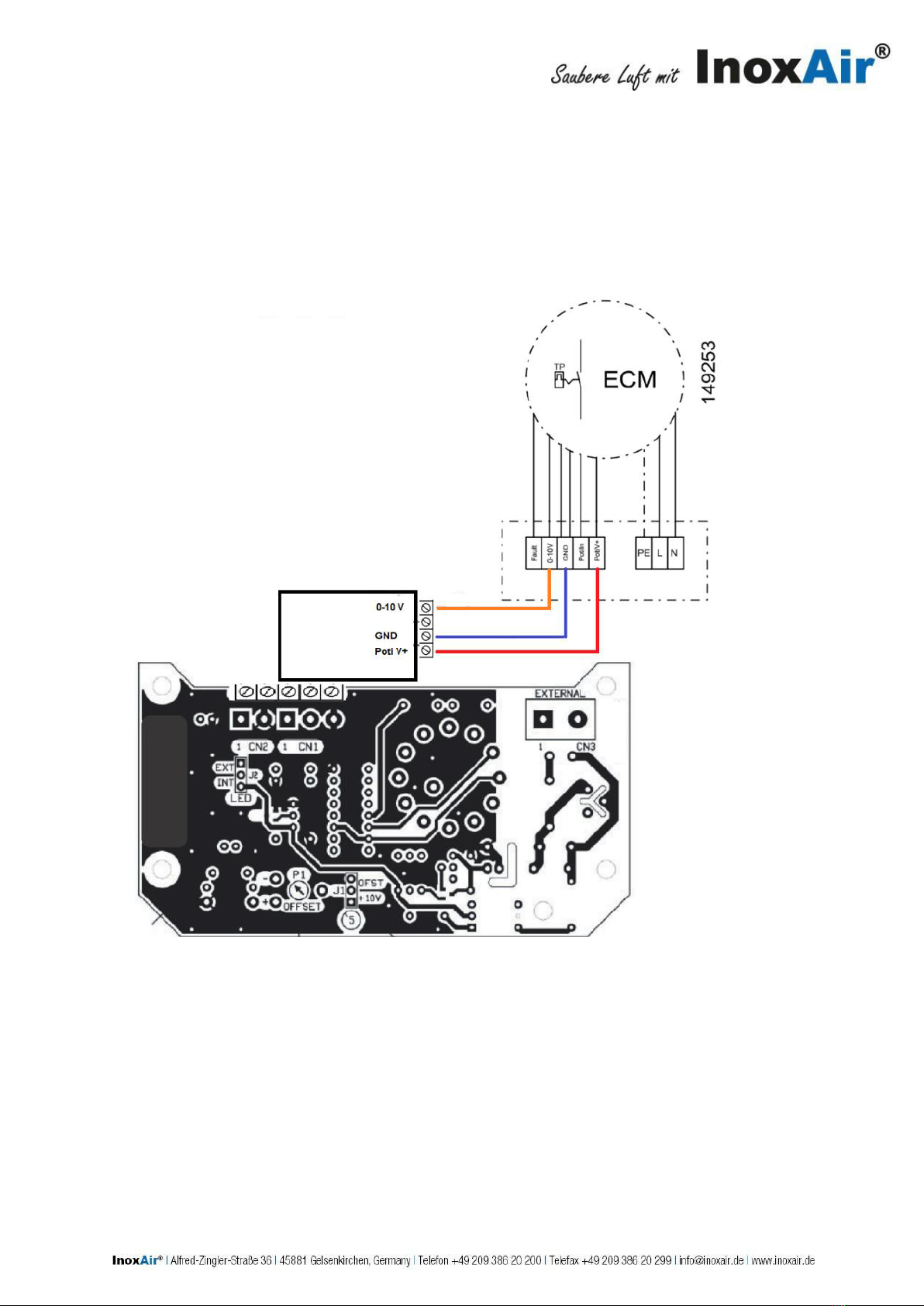
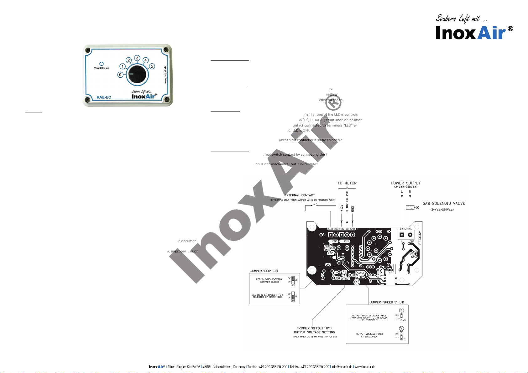
must no longer be ac-cessible. Make the electrical
connections to the unit according to the circuit diagram!
Before commissioning, make sure that all gaskets and seals
in the plug-in connections are correctly fitted and
undamaged in order to prevent fluids and foreign matter
getting into the product. Information signs must not be
changed or removed! Always operate the fan with the ow in
the correct direction (see the marking on the unit)! Install the
unit so that it is accessible for maintenance and cleaning, and
can be readily removed!
Applies for versions with led out thermal contact: No war-
ranty in case of a not connected Thermal Contact. Damages
caused by overheating will not be considered.
Operating Conditions
Do not operate ruck fans in a potentially explosive atmos-
phere! The maximum ambient temperature on the typeplate
must not be exceeded. Verify that the mains voltage corre-
sponds to the voltage on the typeplate.
Maintenance
ruck fans are maintenance free except for cleaning at the
recommended intervals. Make sure that no connections or
components are loosened unless the device is disconnected
from the mains. Secure the plant so that it cannot be switched
on again unintentionally! Individual components must not be
interchanged. For example, the components intended for one
product may not be used for other products. Deposits from
dust laden air will in time accumulate on the impeller and hou-
sing. This leads to lower performance, imbalance in the unit,
and reduced lifespan. Clean the impeller with a brush or cloth.
Attention! Do not remove or shift balance weights. Under no
circumstances should the interior be cleaned with water or a
high pressure cleaner! By installing an air lter the cleaning
interval can be considerably extended or avoided!
Disposal
Careless disposal of the unit may cause pollution. Please dis-
pose of the unit in accordance with the national requirements
that apply in your country.
EC Declaration of Conformity
As required by EC Directive
Electromagnetic Compatibility (EMC)
Directive 2004/108/EC
The manufacturer InoxAir GmbH
Alfred-Zingler-Str. 36
D-45881 Gelsenkirchen
Tel.: +49 (0)209 386 20 200
declares herewith that the following partly completed ma-
chines in their conception and design, and in the versions
marketed by us comply with the requirements of the named
EC directives. In the event of any changes to the partly com-
pleted machine not approved by us, this declaration loses its
validity.
Product designation: Multi Purpose Cubic Box
Type designation:
ELQ, MPC, MPC...TW, MPS, MPS...F
The following harmonised standards were used:
DIN EN 61000-6-2 Electromagnetic Compatibility (EMC) -
Part 6-2: Generic standards: Immunity for industrial
environments.
DIN EN 61000-6-3 Electromagnetic Compatibility (EMC) -
Part 6-3: Generic standards: Emission standard for
residential, commercial and light-industrial environ-
ments.
Responsibility for this declarations rests with:
InoxAir GmbH
Alfred-Zingler-Str .36
D-45881 Gelsenkirchen
These Installation Instructions contain important information
to enable the safe and proper installation, transport, com-
missioning, maintenance and dismounting of ruck fans. The
product has been manufactured according to the state of
the art. Nevertheless, hazards may arise that could
endanger persons and cause damage to property if the
following safety and warning directions in these instructions
are not observed. The product shall only be taken into
service after the Installation Instructions and the Safety
Notes have been read and understood. Keep these
instructions in a loca-tion where they are accessible to
all users at all times. If the equipment is passed on to a
third party, the Instal-lation Instructions must always be
handed over with it.
ruck fans are subject to continual quality control, and comply
with the regulations valid at the time of dispatch. Because the
products are being constantly developed, we reserve the right
to make changes to the products at any time and without prior
notice. We accept no liability for the correctness and
comple-teness of these Installation Instructions.
The warranty only applies to the delivered configuration.
We accept no claims under guarantee or warranty,
and no liability for injury to persons or damage to
property arising from incorrect installation, improper
use, and/or inappropriate handling.
Safety Notes
The ruck fan is a component in terms of the Machinery Direc-
tive 2006/42/EC (partial machine). The product is not a ready-
for-use machine as defined by the Machinery Directive. It is
in-tended exclusively for installation in a machine or in
ventilation equipment and installations or for combination with
other com-ponents to form a machine or installation. The
product may be commissioned only if it is integrated into the
machine/system for which it is intended, and if that machine/
system fully com-plies with the EC Machinery Directive.
Never use a ruck fan if it is not in good technical order
and condition! Check the product for visible defects, for
example cracks in the housing, missing rivets, screws and
covers, and any other application-relevant defects! Only use
the product within the performance range specified in the
technical data and on the typeplate! Protection against
contact, protection against being sucked in, and safety
distances must comply with DIN EN 13857. (by installing
protective grids or sufficiently long tubes)! Generally
prescribed electrical and mechanical protection devices
are to be provided by the client! Electrical connections
and re-pairs may only be carried out by qualified
electricians! Before carrying out any installation or
maintenance work, isolate unit from the mains supply! The
product may only be operated by personnel with limited
physical, sensory or mental capacities if they are supervised
or have been instructed by a responsible person. Children
must be kept away from the product.
Transport and storage
Transport and storage may only be carried out by
specialist personnel according to the Installation
Instructions and the relevant, valid regulations. Check that
the delivery is as speci-fied on the delivery note; make sure it
is complete and correct, and check for any damage. Any
missing quantities or damage incurred during transport must
be confirmed by the carrier in writing. No liability is
accepted if this condition is not obser-ved. Transport the
equipment in the original packaging with suitable lifting
gear, or on the transport equipment indicated. Avoid
damage to or deformation of the housing. The product must
be stored in a dry area and protected from the weather in
the original packaging. Storage temperature range: –10°C
to +40°C. Avoid severe temperature fluctuations. If the
unit has been stored for over a year, check by hand that
the fan turns freely.
DGB
InoxAir
InoxAir
InoxAir
InoxAir
InoxAir
InoxAir
InoxAir
InoxAir
InoxAir
InoxAir
InoxAir
InoxAir
Alfred-Zingler-Straße 36
45881 Gelsenkirchen
info@inoxair.de
www.inoxair.de
Tel.
Fax
.
+49 209 386 20 200
+49 209 386 20 299
InoxAir®
This manual suits for next models
18
Table of contents