Keltech SNA-36 User manual

729 S. Grove St., Delton, MI 49046
TEL: 269-623-6395 • 800-999-4320 FAX: 269-623-6398
Installation
215-1815 Rev. B; ECN 130011
© 2014 Keltech
Page 1 of 17 10/17/2014
SNA-Series
Tankless Heater Models
SNA-36
SNA-54
SNA-63
SNA-72
SNA-108
SNA-126
SNA-144
Voltage options
for models:
600V 3-phase
480V 3-phase
415V 3-phase
400V 3-phase
380V 3-phase
Table of Contents
Pre-Installation Information .........................2–3
Storage Instructions .................................3
Mounting Heater....................................4
Plumbing Installation ................................5
Electric Installation ..................................6
Start Up Check List .................................7
Start Up ..........................................8
Digital Controller Operation ...........................9
Operational Test ................................10–11
TepidGuard™Flow Conditions ........................11
Product Options ................................11–12
Maintenance......................................12
Troubleshooting ................................12–13
Special Installation & Operating Instructions ..........14–17
IMPORTANT!
Read this entire installation manual to ensure proper installation. When finished with
the installation, file this manual with the owner or maintenance department. Compliance
and conformity to local codes and ordinances is the responsibility of the installer.
Separate parts from packaging and make sure all parts are accounted for before
discarding packaging material. If any parts are missing, do not begin installation until
you obtain the missing parts.
Make sure that all water supply lines have been flushed and then completely turned off
before beginning installation. Debris in supply lines can cause valves to malfunction.
Product warranties may be found on our web site www.keltech-inc.com.
Installation
THIS
SIDE
UP
Packing List
•
•
•
•

2
SNA-Series Tankless Heater Installation
10/17/2014 Keltech • 215-1815 Rev. B; ECN 130011
Pre-Installation Information
WARNING! A qualified plumber or electrician should install and service this system. Install system
according to these instructions and in compliance with national and local codes.
Read this manual BEFORE using this equipment. Failure to read and follow all safety and
use information can result in death, serious personal injury, minor burns, property damage, or
damage to the equipment. Keep this Manual for future reference. Failure to comply with proper
installation and maintenance instructions could contribute to the heater’s failure.
ASSE standard 1016, 1069 or 1070 listed devices should be used at fixtures to prevent possible
injury. Severe bodily injury including scalding, chilling, and/or death may result depending
upon system water pressure changes and/or supply water temperature changes.
These heaters should never be used to provide “anti-scald” or “anti-chill” service.
These heaters do not provide protection from supply or outlet pipe freezing.
Failure to ground this system may result in death or serious injury. Consult local building
and plumbing codes prior to installation. Should these codes differ from the information in
the Manual, follow the local codes. Inquire with governing authorities for additional local
requirements.
Regular checking and cleaning of the heater’s internal components and check stops is
necessary for maximum life and proper product function. Periodic inspection and yearly
maintenance by a licensed contractor is required. Corrosive water conditions, and/or
unauthorized adjustments or repairs could render the heater ineffective for its intended service.
Frequency of cleaning and inspection depends upon local water conditions. For heaters with
adjustable output temperatures, check and adjust as needed at initial installation and on a
quarterly basis.
General Information
The Keltech Tankless Water Heater provides instant and precise temperature-controlled hot water. To insure proper
performance, install the heater according to the following installation instructions and in compliance with applicable
national and local codes.
Keltech can supply heaters for most commercial and industrial hot water applications. Flow rates and temperature
figures are important for proper sizing. If needed to meet certain temperature demands, flow control devices are
readily available. See Table 3 for temperature rise specifications. Contact your local Keltech Representative or
KELTECH, INC. for further information on available models.
Operation and Setup
SNA-Series heaters supply an unlimited amount of hot water with specific flow and temperature rise capabilities.
These heaters are energy efficient, reliable, and provide optimum performance in the most demanding applications.
Application Specific Requirements
The SNA-Series can be used in many different applications that require safety showers or safety shower eye/face
wash combination fixtures.
For use in a recirculation loop, the incoming loop temperature should not exceed 140°F (60°C) to ensure water
cooling of the solid state relay.
For applications utilizing quick close valves or solenoid valves, it is important to install a hammer arrestor or surge
tank close to the point of use to absorb pressure spikes.
ASME CERTIFICATION: Please verify if your State Boiler Code requires ASME Certification and that you have the
proper heater to meet your code requirements prior to installation.
Installation Considerations
Maximum operating pressure: 160psi.
Minimum flow activation: 1.5 gpm

3
Installation SNA-Series Tankless Heater
Keltech • 215-1815 Rev. B; ECN 130011 10/17/2014
SCCR Rating
Keltech Electric Tankless Water Heaters are certified by ETL to UL499, UL50E and CSA22.2 No 88. It is designed to
comply with UL508A.
The SCCR load rating is marked on the enclosure per UL508A requirements for Water Heaters controlling a resistive
heating element load.
IMPORTANT! For safe operation of the heater, observe all the warning labels as indicated. Sample labels
provided below.
Storage Instructions
IMPORTANT! Keep Keltech Electric Tankless Water Heaters stored in original packaging until installation.
Recommended storage criteria:
Store Keltech Electric Tankless Water Heaters where temperatures exceed 35ºF (5º C) at all times.
Indoor storage is recommended.
Minimize excessive on-site transport to reduce risk of shock and impact damage.
Alternate storage:
If in the original crate, Keltech Electric Tankless Water Heaters will withstand outside storage for approximately 1
month in most climates.
If the Keltech Electric Tankless Water Heater is stored in an outdoor environment, care should be taken to protect the
heaters from:
• Rain or other falling precipitation via tarp or other waterproof media.
• Runoff and accumulation of groundwater from any source that may exceed 1 inch.
NOTE: For heaters with ENHT freeze protection option: If the heater is stored where the temperature could fall below
45°F(7°C), the heater must be powered immediately after hydro testing to ensure internal freeze protection
components are activated. Once the heater is installed and the on-site plumbing has been hydro tested, the
power supply must remain constant until the risk of freeze is eliminated. If this is not possible, do not allow
the heater to remain full of water. The heater must be drained of water. Freezing of the heater can
cause serious damage. Follow notes in Start Up Check List section.
Packaging
Crates are constructed from 3/4" OSB.
Crate dimensions approx: 82" x 48" x 24" (2083mm x 1219mm x 610mm)
Crates should not be stacked more than 2 high.
All crates must be stacked evenly and horizontally.
Safety issues related to packaging:
• Product should be transported with the care associated to packages labeled “FRAGILE” even if packaging is not
marked accordingly.
• Standard safety procedures for forklift transport and large items less than 1000lbs should be followed at all times.
• When stored, crate must be supported in entirety of its length and width.

4
SNA-Series Tankless Heater Installation
10/17/2014 Keltech • 215-1815 Rev. B; ECN 130011
Mounting Heater
1
WARNING! HIGH VOLTAGE SHOCK. Disconnect power supply before performing any work inside
the heater enclosure.
CAUTION! If heater is installed where freezing can occur, specify Keltech's ENHT Freeze
Protection Option.
A
Drain water from heat exchanger through
2 drain plugs located at the bottom of the
heat exchanger. Power must be removed
from the heater and not restored until all
air has been bled off.
CSet heater in a vertical, upright position
with the water outlet located at top.
DSecure heater by bolting each leg to the
floor using 3/8” anchor bolts (See Figure 1).
E
Install the pressure and temperature relief
valve on hot water outlet immediately
following the union.
NOTE: Valve must empty into a drain
(See Figure 2).
B
Remove air by re-installing drain plugs
and open inlet supply valve to apply
line pressure to heater. Open fixture
connected to the heater outlet for (5)
minutes or until all air has been removed
from the heater. Fixture can be closed
and power restored to the heater.
For best results, install heater as close as possible to the point of use.
Installation is to be performed by licensed trades people.
Long pipe runs are not recommended. A heat loss of 1°F for every 10ft (3 meters) of uninsulated
pipe can occur.
When determining a mounting location, ensure accessibility of the enclosure door and other
plumbing for service and maintenance.
FIGURE 1
Bottom View - Leg Mounting Holes
30" (762mm)
12"
(305mm)
2"
(51mm)
4"
(102mm)
8"
(204mm)
6-7/8"
(175mm)
16-1/4"
(413mm)
3-7/8"
(99mm)
3/4" x 7/16" Slot
(6) Places

5
Installation SNA-Series Tankless Heater
Keltech • 215-1815 Rev. B; ECN 130011 10/17/2014
Plumbing Installation
2
CAUTION! To avoid water damage, install a drain
pipe from the pressure relief valve to
an unrestricted drain.
B
Install one union on the water inlet side of the
heater and another union upstream of the 100
Mesh (150 micron) y-strainer.
Install one union on the water outlet side of the
heater and another after the P & T Relief Valve.
Install one union on the TepidGuard™discharge outlet.
Install the pressure relief valve (150 psi) and outlet
plumbing of heater per code requirements and
route relief valve discharge to drain. Make sure no
shutoff valve is between the relief valve discharge
and the drain.
CUse 1-1/4" hard copper tubing or pipe as needed.
AInstall shutoff valve above (upstream of) the heater.
Failure to install proper filtration may result
in a flow sensor malfunction.
See Figure 2 for reference and suggested
installation configuration.
If end use fixture is not at the highest point in
the plumbing loop, then an automatic air vent
valve must be added at the highest point in the
system or at any drop to eliminate trapped air.
Components Needed:
• (5) Union 1-1/4"
• Shutoff Valve
• Pressure and Temperature Relief Valve (150 psi)
• Y-Strainer (100 mesh) or Inline Filter (150 microns)
• (2) Gate or Ball Type Valves
• Drain pipe
• Elbows, nipples and fittings as needed
Dim. "A" Dim. "B" Dim. "C"
36kW 60"(1524) 48"(1219) 36"(914)
54kW 60"(1524) 48"(1219) 36"(914)
63kW 72"(1829) 60"(1524) 48"(1219)
72kW 60"(1524) 48"(1219) 36"(914)
108kW 60"(1524) 48"(1219) 36"(914)
126kW 72"(1829) 60"(1524) 48"(1219)
144kW 72"(1829) 60"(1524) 48"(1219)
FIGURE 2
Dimensions,
Plumbing
and Electrical
Configurations
B
C
A
31-1/2"
(800mm)
23-1/2" (597mm)
5-1/2" (140mm)
15-1/4"
(387mm)
3-3/4"
(95mm)
6" (152mm)
6" (152mm)
Access Panel
30"
(762mm)
29"
(737mm)
12"
(305mm)
1-1/4" Female NPT
Outlet
1-1/4" NPT
Female
Inlet
Suggested Location For
Power Entrance. Holes
Provided By Installer.
Relief
Valve
Outlet
Inlet
"Y" Strainer
To Drain
Threaded
Union
Optional
Fused
Disconnect
Optional
Fused
Disconnect
1-1/4" NPT
Female
"TepidGuard™"
Discharge
(Drain)
"TepidGuard™"
Discharge
(Drain)
Maintain area
above Access
Panel for height
"C" to be clear of
obstructions
Rotate outlet 90˚
during installation
for adequate
clearance
Suggested Installation Configuration
Components provided by installer unless otherwise specified.
Reference the product options sections or contact your local Bradley
Representative for product options.

6
SNA-Series Tankless Heater Installation
10/17/2014 Keltech • 215-1815 Rev. B; ECN 130011
Electric Installation
3
CAUTION! Failure to properly ground the unit(s) per the National Electric Code could result in injury or death.
B
Using a hole punch, cut a hole the proper
size for conduit connection; large enough
for the wire size for each heater. The
connectors need to be rated NEMA4/4X
to ensure proper sealing of the enclosure.
(See Figure 2 for suggested location).
AOpen enclosure door.
CRun wires through the appropriate size
conduit.
DConnect wires to the system terminal
block or fused disconnect inside the
enclosure.
EConnect the ground wire to the stud
provided with the “Ground” label beneath it.
Any option that requires field wiring must
be done with 600V cable per the schematic
shipped with the heater.
Use a 4-core cable or multi-stranded
machine tool wire from an approved
isolating 3-pole switch or circuit breaker.
Make sure the electrical cable is the
correct size to carry 100% of the full load
current. See Table 1 for proper wire sizes.
IMPORTANT! All Keltech heaters must be fused in accordance with National Electric Code for the full
load amperage listed on the nameplate rating for each heater.
CAUTION! To avoid damage to the electronics or internal wiring, do not perform any brazing or sweat
soldering inside the enclosure.
ELECTRICAL SPECIFICATIONS FOR HEATER (PHASE 3)
Model Voltage Amps kWatts Min Wire
Size
SNA-363/600D 600 35 36 8 AWG*
SNA-543/600D 600 52 54 6 AWG*
SNA-633/600D 600 61 63 4 AWG*
SNA-723/600D 600 69 72 4 AWG*
SNA-1083/600D 600 104 108 2 AWG*
SNA-1263/600D 600 121 126 1 AWG*
SNA-1443/600D 600 139 144 1/0 AWG*
SNA-363/480D 480 43 36 6 AWG*
SNA-543/480D 480 65 54 4 AWG*
SNA-633/480D 480 76 63 4 AWG*
SNA-723/480D 480 87 72 3 AWG*
SNA-1083/480D 480 130 108 1 AWG*
SNA-1263/480D 480 152 126 1/0 AWG*
SNA-1443/480D 480 174 144 2/0 AWG*
SNA-363/415D 415 38 27 8 AWG*
SNA-543/415D 415 56 40 6 AWG*
SNA-633/415D 415 65 47 4 AWG*
SNA-723/415D 415 75 54 4 AWG*
SNA-1083/415D 415 113 81 2 AWG*
SNA-1263/415D 415 131 94 1 AWG*
SNA-1443/415D 415 150 108 1/0 AWG*
SNA-363/400D 400 36 25 8 AWG*
SNA-543/400D 400 53 37 6 AWG*
SNA-633/400D 400 64 44 4 AWG*
SNA-723/400D 400 72 50 4 AWG*
SNA-1083/400D 400 108 75 2 AWG*
SNA-1263/400D 400 126 87 1 AWG*
SNA-1443/400D 400 144 100 1/0 AWG*
SNA-363/380D 380 35 23 8 AWG*
SNA-543/380D 380 50 33 6 AWG*
SNA-633/380D 380 59 39 6 AWG*
SNA-723/380D 380 68 45 4 AWG*
SNA-1083/380D 380 103 68 2 AWG*
SNA-1263/380D 380 120 79 1 AWG*
SNA-1443/380D 380 137 90 1/0 AWG*
TABLE 1
* Based on the NEC Table 310.15 for 75°C insulated wire @ 30°C Ambient

7
Installation SNA-Series Tankless Heater
Keltech • 215-1815 Rev. B; ECN 130011 10/17/2014
Start Up Check List
4
Plumbing
System is set in a vertical, level, and upright position with the outlet located at the top. System is mounted by
legs (2) bolted to the floor (3/8" dia. minimum).
Confirm Installation of shutoff valve above (upstream of) the union on the inlet connection. Confirm Installation of
a Y-strainer (100 mesh screen) or inline filter (150 micron) between the inlet shutoff valve and the heater.
Pressure and temperature relief valve is installed on tepid water outlet immediately following the union. No valve
or restriction is between the relief valve and the system or the relief valve and drain. Shutoff valve is installed
after pressure and temperature relief valve on outlet if required by local or national plumbing codes.
If the hot water process is not at the highest point in the plumbing loop, then an automatic air vent valve must be
added at the highest point in the system plumbing loop to eliminate trapped air.
Electrical
Verify supply voltage matches the indicated voltage on the Serial Tag. Serial Tag is located within the heater
enclosure on the upper right corner of the back plate (mounting plate). Voltage can also be verified on the SCCR
Tag on the door of the heater.
Appropriate conduit is installed properly, secured and sealed to unit enclosure per NEC and hazard
location requirements .
Appropriate conductors for unit routed through conduit and secured to power block inside the enclosure
(See Table 1). All electrical is installed in accordance with national and local electrical codes, including fuse
size and rating.
Appropriate earth ground is installed to the lug provided on enclosure backplate.

8
SNA-Series Tankless Heater Installation
10/17/2014 Keltech • 215-1815 Rev. B; ECN 130011
Start Up
5
ASlowly turn on water supply to the unit
with the enclosure door open.
CTurn off the connected process and
check the entire system to verify leak-free
installation.
G
Turn on the connected process; observe
output temperature rise to setpoint. NOTE:
Top portion of temperature controller
displays output temperature, bottom
displays setpoint temperature (setpoint
temp is not adjustable on SNA Models).
DClose enclosure door and secure.
Depress the Emergency Stop Button.
EEnergize the electrical service to the unit
by switching on the breaker.
F
Pull out Emergency Stop Button.
After a six second discharge from the
TepidGuard overshoot purge system, the
unit is now in the ready-state.
B
Slowly turn on the water outlet valve,
activate the connected process requiring
heated water (faucet, shower, etc.), then
flush the system for 5 minutes to ensure all
air is purged from the system. CAUTION!
Failure to bleed air properly will damage
elements and cause heater malfunction.
Be sure that plumbing and electrical are complete per Start Up Check List.
IMPORTANT! If your heater is mounted in an area where freezing temperatures are possible, an ENHT
Freeze Protection Option should be specified. Heaters must be powered at all times to be
Freeze Protected. If continuous power is not possible, do not allow the heater to remain
full of water. Freezing of the heater can cause serious damage.
IMPORTANT! If your heater has the EXP2 option and is located in a Class I Division II area, please review
Special Installation & Operation Instructions section for all proper electrical connections
and sealing to ensure the installation will provide the proper protection.
WARNING! Make sure the breaker for the heater is OFF.
H
When startup is complete, leave circuit
breaker in the ON position and the
Emergency Stop Button on the door
pulled out. The Green power light should
be illuminated.

9
Installation SNA-Series Tankless Heater
Keltech • 215-1815 Rev. B; ECN 130011 10/17/2014
Digital Controller Operation
6
The preprogrammed digital controller is mounted through the bezel on the enclosure door. The digital
controller will not be powered until water is flowing through the heater. The bottom display will then display
the setpoint temperature (See Digital Controller Operation section for more information).
Description Upper Display Lower Display Function
EZ Key Toggles output on/off (Disabled on SNA Models)
Setpoint Up Button Increases output temperature (Disabled on SNA
Models)
Setpoint Down Button Decreases output temperature (Disabled on
SNA Models)
Infinity Key Back to Home page
Advance Key Advances through parameter prompts
Auto, Man, Off C.r71 Turns Control Loop On/Manual/Off (Disabled on
SNA Models)
XX.X% h.Pr1 Heater Power % (Disabled on SNA Models)
no AUt1 Autotune (Contact Factory) (Disabled on SNA
Models)
C or F C_F1 Change Temperature Units from F to C
Output Indicators (1-5) Output 1,2,3,4 or 5 are active and operating if
these LEDs are illuminated.
Setpoint Temperature
(Lower Display)
In Green Displays:
• Setpoint
• Percent Power
• Temperature units F or C
• Menu prompt name
• Alarm code
Output Temperature
(Upper Display)
In Red Displays:
• Actual process temp. of outgoing water
• Prompt parameter value
• Error code (feature disabled)
TABLE 2
Output Indicators
Output Temp.
Output
Temp.
Blank
Setpoint
Temp.
Setpoint Temp.
Setpoint Up
Setpoint Down
Advance KeyInfinity Key
EZ Key
FIGURE 3
Layout Diagram
FIGURE 4
ON - Heating
FIGURE 5
OFF - No Flow
1
2
3
4
5
1
2
3
4
5
1
2
3
4
5

10
SNA-Series Tankless Heater Installation
10/17/2014 Keltech • 215-1815 Rev. B; ECN 130011
Perform Operational Test No. 1
AEnsure the enclosure door is closed.
BSet the 3-pole switch or circuit breaker to the
ON Position.
C
Pull out the Emergency Stop Button, heater will
automatically perform a 6 second discharge
from the TepidGuard overshoot purge system.
Wait for purge cycle to complete.
E
Test water temperature and stability at
outlet by viewing the display. Controller
displays (in red) the temperature of water
exiting the heater.
F
Deactivate the shower or eyewash. The
flow sensor will electrically open contacts
and remove power from the elements and
controller so that the display is blank and
bank lights are off. Power light stays on.
D
When flow rate reaches approximately
1.5gpm, the flow sensor recognizes this
condition and begins the heating process.
When the flow sensor activates:
• Green bank energized lights illuminate on the
front bezel verifying power supply connection to
the heating elements via the solid-state relays.
• Element load lights may be solid or flash
in unison as heating elements modulate
depending on the hot water demand.
• Digital temperature controller shows water
temperature. Additional programming is
not necessary.
Located on the panel are 1 (36-63kW) or
2 (72kW-144kW) green ready lights. When
illuminated, the safety circuit is engaged
and ready for use.
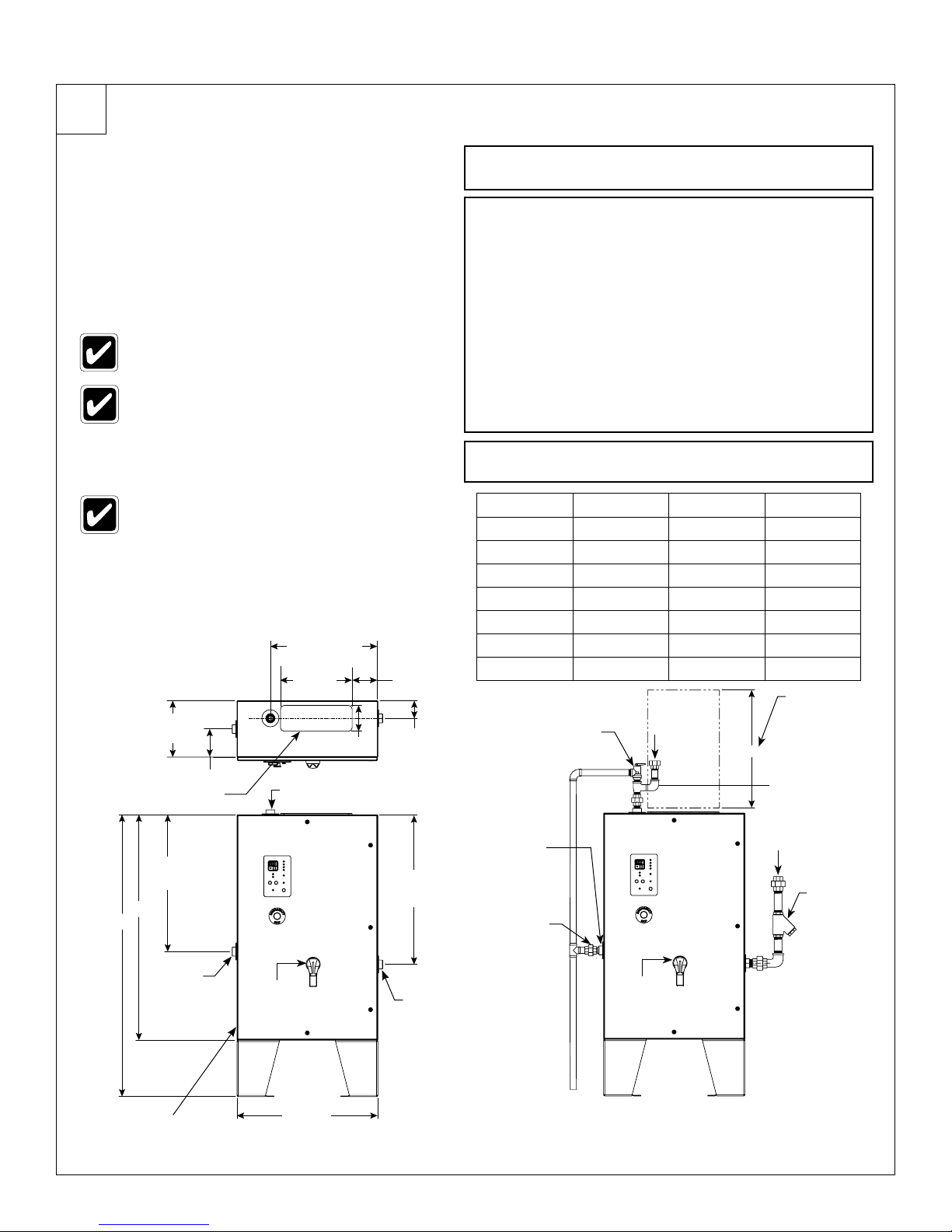
Heaters installed in pump-and-well supplied
water systems may require an operating
pressure adjustment to a differential pressure
of approximately 10 psi. For example, if the
high limit pressure is 40 psi, adjust the low
limit pressure to 30 psi with the pressure
switch located on the supply pump.
Heater will not energize heating elements if the
inlet water temperature is equal to or greater than
the temperature set on the digital controller .
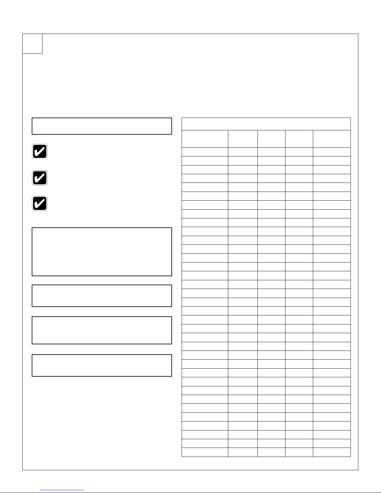
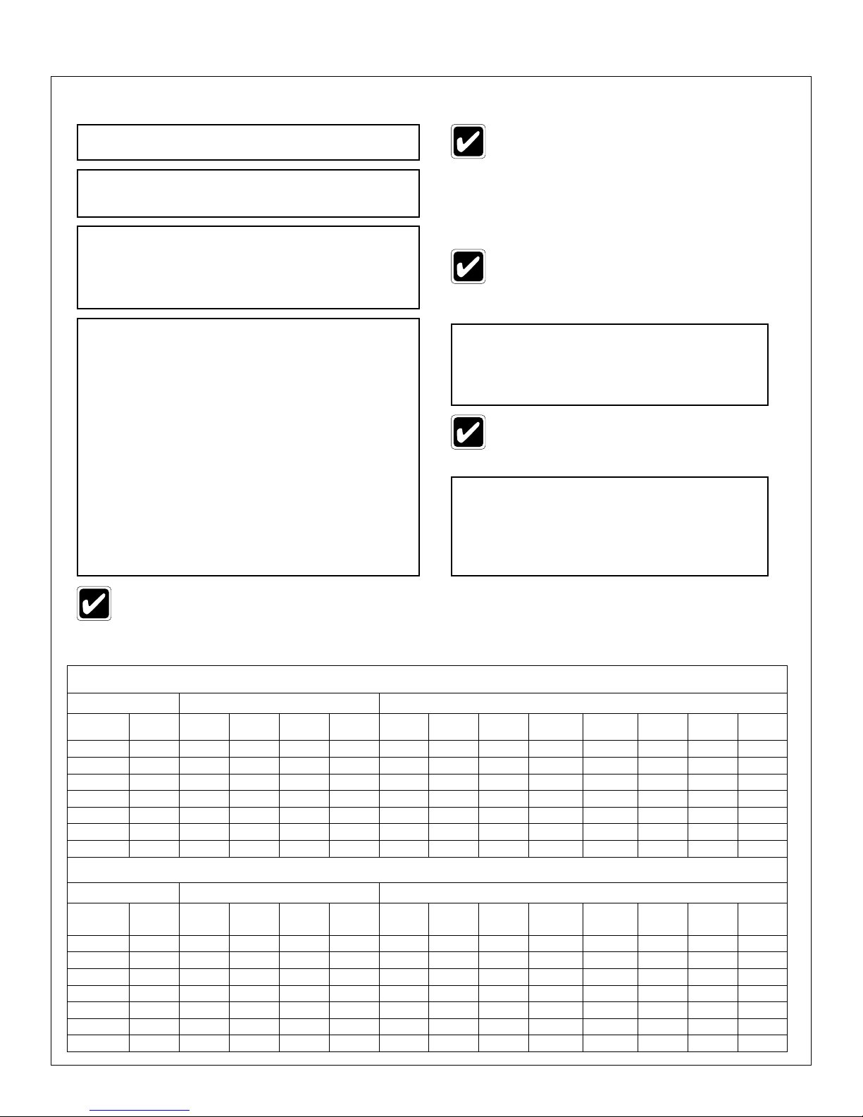
If the water flow exceeds maximum heating capacity of the heater, the temperature of water at the
outlet may be lower than the temperature selected on the controller. See Table 3 to determine maximum
temperature rise capabilities.
Maximum Temperature Rise (GPM & °F)
Low Flow Activation* (1.5gpm) High Flow Activation*(15 gpm)
Models
480/600V
kW Low/
High
2.5 gpm
ΔT °F
3 gpm
ΔT °F
5 gpm
ΔT °F
8 gpm
ΔT °F
15gpm
ΔT °F
20gpm
ΔT °F
25 gpm
ΔT °F
30gpm
ΔT °F
35gpm
ΔT °F
40 gpm
ΔT °F
45gpm
ΔT °F
50gpm
ΔT °F
SNA-363 12/36 33 27 16 10 16 12 10
SNA-543 18/54 49 41 25 15 25 18 15 12 10
SNA-633 24/63 57 57 29 20 29 22 17 15 12
SNA-723 27/72 73 61 37 23 32 24 19 16 14 10
SNA-1083 40/108 109 90 54 34 49 36 29 24 21 18 16 14
SNA-1263 47/126 128 106 64 40 57 43 34 28 24 21 19 17
SNA-1443 54/144 147 122 73 46 65 49 39 33 28 24 21 19
Maximum Temperature Rise (LPM & °C)
Low Flow Activation* (1.5gpm) High Flow Activation*(15 gpm)
Models
480/600V
kW Low/
High
9.5 lpm
ΔT °C
11.3 lpm
ΔT °C
18.9 lpm
ΔT °C
30.3 lpm
ΔT °C
56.7 lpm
ΔT °C
75.6 lpm
ΔT °C
94.5 lpm
ΔT °C
113.4 lpm
ΔT °C
132.5 lpm
ΔT °C
151 lpm
ΔT °C
170.3lpm
ΔT °C
189.3lpm
ΔT °C
SNA-363 12/36 18 15 9 6 9 7 6
SNA-543 18/54 27 23 10 8 14 10 8 7 6
SNA-633 24/63 32 32 16 11 16 12 9 8 7
SNA-723 27/72 40 34 21 13 18 13 11 9 8 6
SNA-1083 40/108 60 50 30 19 27 20 16 13 12 10 9 8
SNA-1263 47/126 71 59 36 22 32 24 19 16 13 21 11 9
SNA-1443 54/144 82 68 41 26 36 27 22 18 16 13 21 11
TABLE 3
…continued on next page

11
Installation SNA-Series Tankless Heater
Keltech • 215-1815 Rev. B; ECN 130011 10/17/2014
Output heating capacity is reduced if these heaters are installed on 415V, 400V or 380V 3-ph.
Contact the factory to supply this information. Satisfactory performance of the heater is dependent upon a specific
flow rate vs temperature rise capability. If the desired temperature is not achieved, please verify the following:
1. Circuit breaker is on and rated for the maximum power draw.
2. Heater is drawing the proper current for the supply voltage on all 3 phases.
3. All 3 phase indicator lights are lit (not flashing) indicating maximum power draw and maximum
amperage is being drawn.
4. Flow rate and temperature rise requirements are compatible with the heater specifications.
5. Verify there is no additional supply of cold water entering the line downstream of the heater.
TepidGuard™Flow Conditions
When a low flow condition (less than 15 gpm) occurs, such as operation of the eye/facewash individual elements are
energize to supply water for the eye/facewash and/or drench hose. One set of PID values is selected on the controller
for accurate temperature control at low flow conditions.
When the heater detects high flow conditions (greater than 15 gpm), all elements are energized. A second set of PID
values is selected on the controller for accurate temperature control at high flow conditions.
When the heater shuts down or switches from high to a low flow condition, the purge valve opens and purges the
heater of latent (excess) heat. This anti-scald feature works both actively at the end of each shower or passively
if sitting in an environment that may exceed the 95°F (35°C). This TepidGuard™ system ensures safe water
temperatures at both the eyewash and shower stations.
Product Options
AL3 & AL3-SL Temperature Alarms: Alerts you to an over or under temperature situation.
GF (Ground Fault): Detects electrical leakage from external sources to protect equipment, electronics, and the heat
exchanger from being damaged in the event of a power fault. After turning on water, then power, test ground fault:
1. Press GF Test button.
2. Watch for ground fault light to illuminate and Bank Ready light(s) to shut off. The Ground Fault system is active
and in working order.
3. Press the GF Reset button, hold for 2 seconds and release to reset ground fault.
NOTE: If a trip occurs under normal operation DO NOT RESET Ground Fault without evaluation and service.
NOTE: Normal state is Ground Fault light OFF, Bank Ready lights ON.
ENHT Freeze Protection (ENHT & ENHT30): ENHT offers protection to -20°F (-28°C). The ENHT30 offers protection to
-30°F (-34°C). Each level of protection utilizes the normal heater supply voltage. No additional dedicated circuit to the unit
is required during field installation. Freeze protection (ENHT option) includes an internally insulated NEMA 4/4X enclosure
and thermostatically controlled forced air heater to maintain internal temperatures above freezing. ENHT options also
include a connection point for DCS monitoring. In the event of a power interruption or ENHT system failure when internal
enclosure temperatures reach 40°F (4.4°C) or lower, the unit will notify a facilities control/monitoring system that the unit is
unable to maintain freeze protection. Regardless of state of power to the unit, this warning notifies maintenance personnel
and provides an opportunity to correct the condition before any damage occurs to the unit.
NOTE: With this option, three phase power must be continuously applied to the heater for the internal freeze protection
heater to operate properly and provide protection. If three phase power cannot be continuously applied, the heat
exchanger must be completely drained of water and electrically locked out or damage from freezing may occur.
Use Start Up procedure to restart this equipment. This option does not require a separate electrical circuit.
WARNING! Failure to maintain power at all times may result in damage to the heater and void the warranty.
Please utilize the temperature sensor contacts (N.O.) that can provide a signal to a remote
device, DCS monitoring or BMS (Building Management System) signal. When temperature inside
the cabinet drops below 40°F (4°C) operation of the system should be verified.
…continued on next page

12
SNA-Series Tankless Heater Installation
10/17/2014 Keltech • 215-1815 Rev. B; ECN 130011
Maintenance
Preventative maintenance is important for optimal performance of the heater. To ensure the heater works properly, always keep
the inside of the enclosure dry. Moisture inside an enclosure increases the humidity, which condenses on cooler surfaces. This
can cause electrical problems and reduce the efficiency of enclosure insulation. To prevent problems perform the following:
• Keep interior of enclosure dry.
• Seal any weeping leaks in seals or walls. Verify there are no leaks in seals of enclosure and that in high humidity
environments all enclosure egresses are properly sealed.
• Ensure plugs are in place on back side of enclosure.
• Monitor Shower heater performance at each routine safety shower inspection.
• Verify the following lights illuminate with activation of the Shower or Eye/FaceWash:
• Green bank energized lights
• Digital display controller
• Red element load lights 1-4
• Green power light illuminated
• Verify that the heater activates the "TepidGuard" discharge port by purging water whenever the shower is deactivated. If
heater does not perform as expected, take appropriate corrective action by evaluating the cause and repair as necessary.
• Check seals monthly during temperatures above 32°F (0°C) and weekly during temperatures below 32°F(0°C). Check
internal freeze protection system(ENHT, ENHT30) prior to first seasonal freeze for proper performance. The external
heater and internal thermostat are factory set at 55°F(13°C). Check operation weekly during temperatures below
32°F (0°C). See Information in Product Options section for additional information on freeze protection.
• Manual Reset Safeties mounted to the heat exchangers may trip at temperatures below 32°F on heaters equipped
with ENHT or ENHT30. Manual resets are set to trip at 100°F(38°C). Heat trace installed on connected piping can
heat water to temperatures above 100°F(38°C), causing the manual reset safeties to trip. Reset Manual Safeties
and lower heat trace temperature to below 100°F.
Troubleshooting for Controller
Problem Solution
No
Power
Verify power is on.
Check continuity of all internal fuses in control transformer, heating elements or optional Fused
Disconnect circuits.
Check all field service circuit breakers or fuses.
Check the safety interlock door switch to make sure that it is not due to misadjustment or open enclosure door.
Check system temperature limit control to make sure it has not activated due to excessive heat
exchanger temperature or faulty sensor.
Check for loose or disconnected wires.
Check the incoming service connection. Voltage must match name plate rated voltage. Labels are located
on the cabinet door (SCCR) and on upper left of back plate (Serial Number Label).
…continued from previous page
EXP2 (Explosion Proof Purge System): Keltech's EXP2 option makes heaters compliant for classified areas;
Class I Division 2, Groups A–D, T5. The Purge System requires a supply of clean instrument air or inert gas
(provided by installer). This supply maintains a positive internal pressure and prevents the enclosure from filling with
flammable gasses, dusts or vapors from the ambient environment. Complete installation provided in this manual.
FDS Fused Disconnect: Internal fused disconnect interlocks with enclosure door when energized, prohibiting access
to a live cabinet. Select the FDS option for an additional level of safety and convenience at the heater location.
HLW (ASME Certified Heat Exchanger): Available on SNA-63 and larger. The heat Exchanger is made of special
brass and certified by ASME inspector for quality of workmanship.

13
Installation SNA-Series Tankless Heater
Keltech • 215-1815 Rev. B; ECN 130011 10/17/2014
Troubleshooting using the Flow Limit Control Board (FLCB)
Problem Solution
The heater does not work or works intermittently. Check that the flow sensor located at the inlet is spinning
with water running. Check if in Low flow (> 1.5 gpm) that
the FLCB light is on. If in High flow (> 15gpm) both the low
flow light and high flow lights will be illuminated.
Check that water flow through the heater is adequate to
activate the flow sensor at 1.5gpm.
Check that the heater is wired with the proper breaker and
wire size. Refer to Table 1 for proper requirements
Check that the unit is receiving voltage from all 3 phases
of the power source. A load voltage reading is also helpful.
Element Load Bank 1–2 or 3–4 is not energized. Check FLCB with corresponding light indicated:
Bank 1–2 on the front bezel = Bank 1 on the FLCB
Bank 3–4 on the front bezel = Bank 2 on the FLCB.
If the light is off and there is power on. Check if water
temperature is greater than 175˚F. Decrease water
temperatures and restart.
Follow the schematic to perform the following continuity checks:
Emergency stop switch.
Door guard.
High temperature bimetals (Manual Reset Safeties).
Optional ground fault breaker must be in the closed position for the unit to work.
All internal breakers must be in the ON position for the unit to work.
For additional information on Troubleshooting or other information, please call Keltech Inc. technical support at
1-800-999-4320. Please have Model No. and Serial No. available when seeking technical assistance. Serial No.
tag is located in the enclosure on the upper left hand corner of the back plate. Please record and maintain this
information at all times:
SNA- Model No.
Serial No.
High Temp.
Limit Senser
Input
Bank 2 Over
Temp. (OT)
Bank 1 Over
Temp. (OT)
High Flow
Status
Low Flow
Status
Purge/Dump
(SNA Models
Only)

14
SNA-Series Tankless Heater Installation
10/17/2014 Keltech • 215-1815 Rev. B; ECN 130011
Special Installation and Operating Instructions
Tankless Water Heaters With Optional Class I Division 2 Purge EXP2 Option and
EXP2LC and EXP2LCPM
General Information
All Keltech Tankless Water Heaters with a model number suffix of – EXP2 and EXP2LC have been fitted with a Z
purge system to pressurize the enclosure suitable for use in Class I Division 2 Hazardous Locations.
A Continuous Flow (Model CF) or Leakage Compensation (Model LC) Mini-Z Pressurizing System has been fitted to
the bottom of the enclosure (See Figure 6).
Outlet
18"
(458mm)
Max
Explosion proof
sealing fitting
supplied by others
Purge System
Relief Valve
Conduit Hub
Class 1 Div. 2
supplied by others
Inlet
5" (127mm)
1
1
2
3
4
5
6
3
5
6
Suggested region for power
entrance at left/bottom of enclosure.
Entrance hole and components to
be provided by installer.
All plumbing fittings are 1-1/4" NPT
female threaded.
Purge Control Panel
Class 1 Division 2
All installation egress from
panel must be sealed (electrical
conduit) for proper explosion proof
installation.
Spark arrestor with calibration orfice
is located behind the purge control
unit and through the bottom of the
enclosure.
Purge gas/compressed air inlet
fitting here.
FIGURE 6
EXP2 & EXP2LC Installation Notes
1. Any tubing, conduit or fittings connected to the Pressurized Enclosure (PE) must conform to local codes for
flammability ratings.
2. All egress into PE must be plugged and properly sealed to minimize leakage of purge air. Use hazardous
location sealing fittings suitable for Class I locations within 18" of enclosure (See Figure 6).
3. There are two types of purge systems:
EXP2 option is a continuous flow purge system and is calibrated to flow at .9 SCFM. To minimize waste, plug
and seal all openings and conduit.
EXP2LC is a leakage compensation purge intended to have minimal flow after the initial purge time. The PE is
built as leak tight as possible and the LC system merely tops up for any enclosure leakage.
4. The system is designed for use primarily with compressed air. The source of the compressed air must be
from a non-classified area. Purge air must be clean, dry and free of flammable gases. When inert compressed
gasses are used (Nitrogen, for example) the installer and facility manager must take suitable precautions
on-site so that buildup of the inert gas does not present a health hazard. Where risk of asphyxiation exists, a
warning label must be fitted to the Pressurized Enclosure (PE).
5. Adjustment of Purge System is not necessary. System is fully calibrated.
6. Connect to Purge System where indicated in Figure 6. Connection port is 1/4" NPT female. Supply pressure
must be regulated to 60–115 PSI.

15
Installation SNA-Series Tankless Heater
Keltech • 215-1815 Rev. B; ECN 130011 10/17/2014
Non Type Z Pressurized Equipment
An alarm shall be provided to indicate failure of the protective gas supply to maintain the required pressure. Piping for
the protective gas shall be protected against mechanical damage.
Where the compressor intake line passes through a classified location, it shall be constructed of noncombustible
material, designed to prevent leakage of flammable gases, vapors, or dusts into the protective gas, and protected
against mechanical damage and corrosion.
The electrical power for the protective gas supply (blower, compressor, etc.) shall be supplied either from a separate
power source or from the protected enclosure power supply prior to any service disconnects of the protected
enclosure. Any protected enclosure that can be isolated from the protective gas supply shall be equipped with an
alarm. Where an alarm is used to indicate the loss of pressure in the cabinet:
• The alarm shall be located at a constantly attended location.
• The alarm actuator shall take its signal from the protected enclosure and shall not be installed between the
enclosure and the protective gas supply.
• The alarm actuator shall be mechanical, pneumatic, or electrical.
• Electrical alarms and electrical alarm actuators shall be approved for the location in which they are installed.
• No valves shall be permitted between the alarm actuator and the enclosure.
Intrinsically Safe (IS) Installation
FIGURE 7
1. Electrical equipment connected to associated apparatus should not use or generate more than 250 volts.
2. Installation shall be in accordance with the manufacturer's instructions and the National Electrical Code
(ANSI/NFPA 70)
3. For guidance on Installation see ANSI/ISA RP12.6 (Installation of IS Instrument System in Class I
Hazardous Locations).
4. Voc or Vt of associated apparatus is less than Vmax
Isc or IT of associated apparatus is less than Imax
Ci plus capacitance of interconnecting cabling is less than Ca of the associated apparatus
Li plus inductance of interconnecting cabling is less than La fo the associated apparatus
5. "Simple Apparatus" is a device that will not generate or store more than 1.2V, 0,1A, 25mW or 20uJ
Hazardous Location
Class I , Division 2
Groups A, B, C, D
T5 Hazardous (classified) Areas
MiniPurge: Option Code /IS
Vmax = 30v
Imax = 350mA
Ci = 0 Li = 0
Non- Hazardous Location
(or suitably protected enclosure)
Power Supply
Outputs to relays or
power contactors
Intrinsically Safe
Interface Unit
Simple apparatus
device

16
SNA-Series Tankless Heater Installation
10/17/2014 Keltech • 215-1815 Rev. B; ECN 130011
IS Installation continued…
All quarter turn latches in the door of the PE must be fully latched for proper operation. Power to the PE must be
turned off before opening the enclosure.
WARNING! This Pressurized Enclosure shall not be opened unless the area is known to be free of
flammable materials or unless all devices within have been de-energized.
Power shall not be restored after the enclosure has been opened until the enclosure has been purged for allotted
time (See Tables 5 & 6). Time begins when pressure indicator turns green after the door of the enclosure has been
closed and fully latched.
WARNING! Ignition of potentially explosive gas/air mixtures may result if power is turned on before the
allotted purge time!
Expo Technologies CF systems have a Minimum Pressure Sensor set to a pressure of at lease 0.1" WC (.25bars). When
the PE pressure is above this set point the sensor produces a positive Pressurized signal. This is displayed on the Red/
Green indicator located on the Purge System. This signal can be used to operate an electrical contact for a remote Alarm.
This signal may be supplied to the pressure operated switch suitable for Intrinsically Safe circuit in accordance (See Figure
6). When the enclosure pressure falls below the set point of the sensor, the Pressurized signal is removed, and the Alarm
conditions occurs. This Alarm must be located where it can be readily observed according to NFPA496 requirements. No
valves may be fitted between the Expo Technologies system and the alarm switch.
WARNING! Never turn on the power without purging first, unless you have proved the interior of the PE is gas
free and checked that the “Pressurized” indicator is green!
Commissioning Test
Commissioning Leakage Compensation (LC) and Continuous Flow/High Purge Keltech Options EXP2LC
and EXP2 Systems:
1. Open the air or gas supply shutoff valve.
2. Adjust the Flow Control Valve (FCV) so that the enclosure pressure rises to the point where the "Pressurized"
indicator turns green.
3. Lower the PE pressure until the Pressurized indicator turns Red.
4. Open the FCV again and set the PE pressure to a level somewhere between the Minimum Pressure
Sensorset point and the RLV opening pressures. This working pressure is not critical. Enough pressure to keep
the“Pressurized” indicator Green is sufficient.
5. On EXP2 and EXP2LC Purge Systems the timing function if performed by the user. The user must ensure that
the time delay between the indicator turning Yellow and the application of power to the PE is not less than the
minimum time required to purge the PE as shown in the Tables 5 & 6.
Normal Operation: Turn the air supply valve ON to start or OFF to stop the system. The user must close the Power
Switch only after the enclosure has been pressurized and purged sufficiently to ensure that the interior of the enclosure
is gas free. It is the operator’s responsibility to shut off the power as soon as possible after a pressure failure.
PURGE TIME CHART - EXP2 Option
for use with EXPO Mini Z Purge 1ZCF/bp/IS
Model/Enclosure
Group Size
Cubic
Feet
Volume
Exchanges
X 4
Orifice
Size
Orifice
No.
Purge
Time
(Minutes)
SNA-36-54 10 40 0.9 #2 44
SNA-63 12.5 50 0.9 #2 55
SNA-72-108 10 40 0.9 #2 44
SNA-126-144 12.5 50 0.9 #2 55
PURGE TIME CHART - EXP2LC Option
for use with EXPO Mini Z Purge 1ZLC/bp/IS
Model/Enclosure
Group Size
Cubic
Feet
Volume
Exchanges
X 4
Purge
Time
Minutes
SNA-36-54 10 40 6
SNA-63 12.5 50 6
SNA-72-108 10 40 6
SNA-126-144 12.5 50 6
TABLE 5 TABLE 6

17
Installation SNA-Series Tankless Heater
Keltech • 215-1815 Rev. B; ECN 130011 10/17/2014
Special Installation Maintenance
Routine Maintenance of the System (Every 6 months)
Recommended maintenance of the systems is as follows:
Repeat Commissioning test at least every six months. The test includes checking the opening pressure of the Relief
Valve, setting of the Minimum Pressure Sensor, the “Normal Working Pressure” of the enclosure. Test that the interlock
and alarms function correctly.
Check the Relief Valve and any other Spark Arrestors. Remove any debris or corrosion, or replace the Spark Arrestor.
Check the condition of the air supply filter element. Clean or replace it as necessary.
Periodic Maintenance (Every 18-24 months)
At least every two years, the following additional checks are recommended:
Apparatus (Heater, Purge Systems, Alarms etc.) is suitable for the Hazardous Location.
There are not unauthorized modifications.
The source of air is uncontaminated.
The interlock and alarms function correctly.
Approval labels are legible and undamaged.
Adequate spare parts are carried.
The action of pressure failure is correct.
This manual suits for next models
6
Table of contents
Other Keltech Water Heater manuals
Popular Water Heater manuals by other brands

CTC Union
CTC Union EcoZenith I 550 Installation and maintenance manual

Lochinvar
Lochinvar COPPER-FIN II CF401 Designer's guide

Truma
Truma Ultrastore Rapid Operating and installation instructions

STIEBEL ELTRON
STIEBEL ELTRON PSH 30 COMFORT Operation and installation

State Water Heaters
State Water Heaters GP6 50 YTVIT instruction manual

TESY
TESY GCV6SL 804420 B11 TSR Instructions for use and maintenance