kenall TEKDEK TD17 SERIES User manual

When you see this image, you will know the Kenall product shown or described is designed and manufactured in the USA with components purchased from US suppliers, and meets the Buy
American requirements under the ARRA. Kenall has not determined the origin of its domestically purchased components or the subcomponents thereof. May be covered by patents found
at www.kenall.com/patents. Content of specication sheets is subject to change; please consult www.kenall.com for current product details. © 2015 Kenall Mfg. Co. All rights reserved.
www.kenall.com P: 800-4-Kenall F: 262-891-9701 10200 55th Street Kenosha, Wisconsin 53144
1
INSTALLATION INSTRUCTIONS
F-4260_091118
Luminaire for Parking Garages
TEKDEK™LED
IMPORTANT SAFEGUARDS
When using electrical equipment, basic safety precautions should
always be followed, including the following:
THIS PRODUCT MUST BE INSTALLED IN ACCORDANCE WITH THE APPLICABLE
INSTALLATION CODE BY A PERSON FAMILIAR WITH THE CONSTRUCTION AND
OPERATION OF THE PRODUCT AND THE HAZARDS INVOLVED.
CE PRODUIT DOIT ÊTRE INSTALLÉ EN CONFORMITÉ AVEC LE CODE DE
L'INSTALLATION PAR UNE PERSONNE QUI connaît BIEN LA CONSTRUCTION ET
LE FONCTIONNEMENT DU PRODUIT ET LES RISQUES ENCOURUS.
DISCONNECT POWER TO ALL CIRCUITS BEFORE WIRING FIXTURE. INSTALL IN
ACCORDANCE WITH ALL NATIONAL, STATE, AND LOCAL CODES. DO NOT
CONNECT TO AN UNGROUNDED SUPPLY. READ ALL FIXTURE MARKINGS AND
LABELS TO ENSURE CORRECT INSTALLATION OF FIXTURE. SUPPLEMENTAL
INSTRUCTIONS MAY BE LOCATED ON THE FIXTURE, IN ADDITION TO THIS
INSTRUCTION SHEET, REGARDING ORIENTATION, OR MOUNTING RESTRICTIONS.
SAVE THESE INSTRUCTIONS
SAFETY RECOMMENDATION
TD17 SERIES
SAFETY RECOMMENDATION
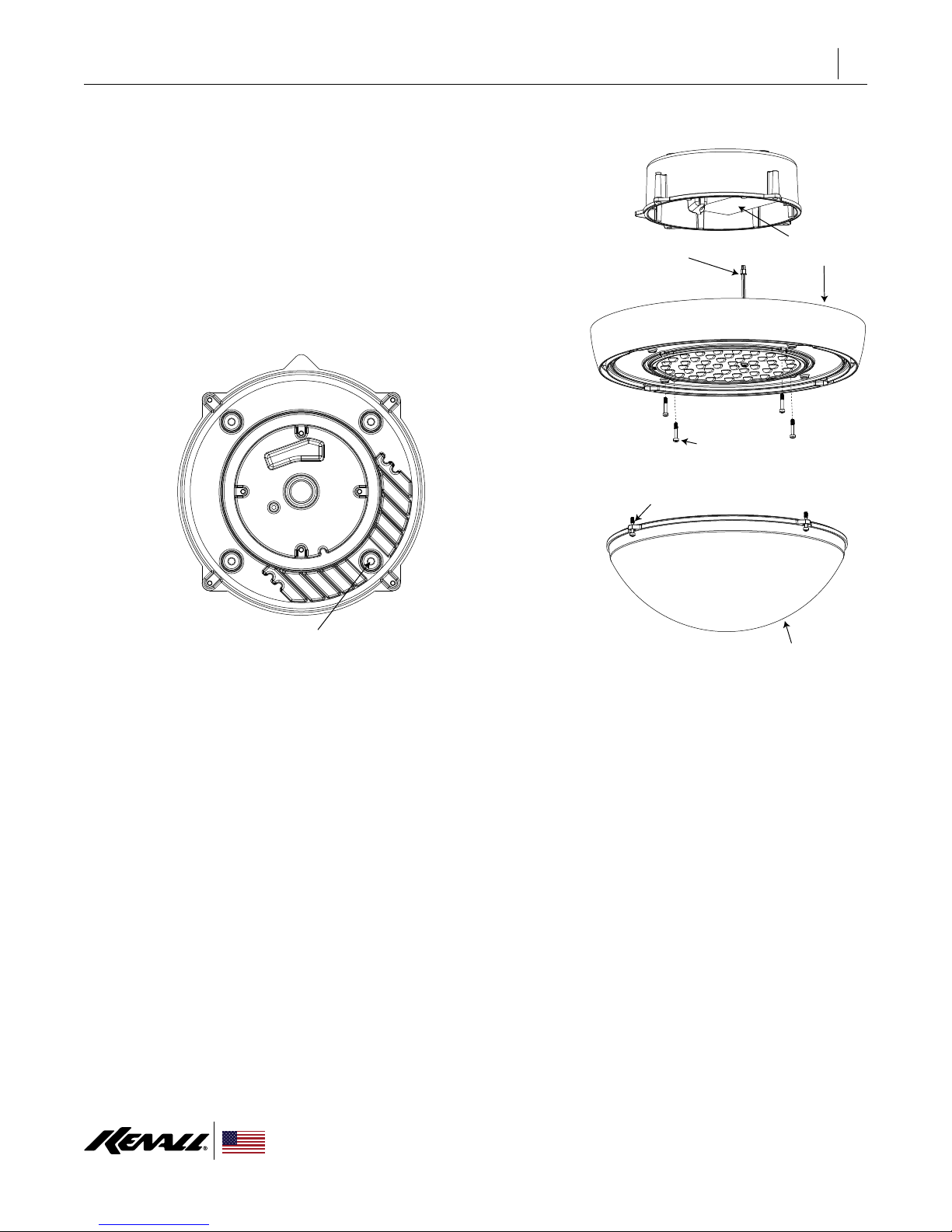
A 1/16" diameter aircraft cable with end-loop (not included) is recommended for
attaching the xture structural to the upper structural.
1/16" DIA. AIRCRAFT CABLE
(SUPPLIED BY OTHERS)
AIRCRAFT CABLE ATTACH
TO UPPER STRUCTURAL
SCREW (SUPPLIED BY OTHERS)
A 1/16" diameter cable with end-loop (not included) is recommended
for attaching the xture structural to the upper structural

When you see this image, you will know the Kenall product shown or described is designed and manufactured in the USA with components purchased from US suppliers, and meets the Buy
American requirements under the ARRA. Kenall has not determined the origin of its domestically purchased components or the subcomponents thereof. May be covered by patents found
at www.kenall.com/patents. Content of specication sheets is subject to change; please consult www.kenall.com for current product details. © 2015 Kenall Mfg. Co. All rights reserved.
www.kenall.com P: 800-4-Kenall F: 262-891-9701 10200 55th Street Kenosha, Wisconsin 53144
2
INSTALLATION INSTRUCTIONS
F-4260_091118
1: Remove tertiary lens (if provided) by unscrewing (4) captive screws.
2: Remove heatsinking/LED base by unscrewing (4) captive screws.
These will be the inner most screws.
3: Disconnect the quick connector wires from the LED board and
the driver.
4: Make electrical connection to J-box (for sizes, see next page). Circuit
wire connection must be in J-box. Install housing to surface using (4)
5/16" diameter mounting holes.
5: Re-assemble by reversing the removal procedure.
DRIVER
QUICK CONNECT HEATSINK/LED BASE
CAPTIVE SCREWS (4)
FOR REMOVING HEATSINK
CAPTIVE SCREWS (4)
TERTIARY LENS (IF PROVIDED)
HOUSING
HOUSING TOP VIEW
5/16” MOUNTING HOLES (4)
DIRECT TO SURFACE INSTALLATION

When you see this image, you will know the Kenall product shown or described is designed and manufactured in the USA with components purchased from US suppliers, and meets the Buy
American requirements under the ARRA. Kenall has not determined the origin of its domestically purchased components or the subcomponents thereof. May be covered by patents found
at www.kenall.com/patents. Content of specication sheets is subject to change; please consult www.kenall.com for current product details. © 2015 Kenall Mfg. Co. All rights reserved.
www.kenall.com P: 800-4-Kenall F: 262-891-9701 10200 55th Street Kenosha, Wisconsin 53144
2
INSTALLATION INSTRUCTIONS
F-4258_010714
QUICK MOUNT KIT INSTALLATION
1: Quick mount plate fastens to a secure J-box.
Screws by others.
2: Align hanger bracket with center slot on
top of xture as shown at right. Fixture
can then hang from bracket while electrical
connections are made.
3: After excess wires are in J-box (see sizes
below), push the xture up to the mounting
plate. Locking hooks should slide through
slots. Twist xture until a “click” is felt or
heard. Fixture is now in place.
LOCKING HOOKS
HANGER BRACKET QUICK MOUNT PLATE
1.
2.
ALIGN HANGER BRACKET
WITH CENTER SLOT
LOCKING HOOK
SLOTS
3.
USED WITH THE FOLLOWING
JUNCTION BOX SIZES:
4" ROUND
4" SQUARE
3-1/2" OCTAGON
3.37
3.37
2.50
2.50
4.77
3.50

When you see this image, you will know the Kenall product shown or described is designed and manufactured in the USA with components purchased from US suppliers, and meets the Buy
American requirements under the ARRA. Kenall has not determined the origin of its domestically purchased components or the subcomponents thereof. May be covered by patents found
at www.kenall.com/patents. Content of specication sheets is subject to change; please consult www.kenall.com for current product details. © 2015 Kenall Mfg. Co. All rights reserved.
www.kenall.com P: 800-4-Kenall F: 262-891-9701 10200 55th Street Kenosha, Wisconsin 53144
2
INSTALLATION INSTRUCTIONS
F-4557_041013
BIRD GUARD INSTALLATION
1. Fasten tab through slots as shown above.
No tools required. Must install before xture is mounted.
2. Bird Guard lays inside of casting.
DIRECT TO SURFACE & QUICK MOUNT

When you see this image, you will know the Kenall product shown or described is designed and manufactured in the USA with components purchased from US suppliers, and meets the Buy
American requirements under the ARRA. Kenall has not determined the origin of its domestically purchased components or the subcomponents thereof. May be covered by patents found
at www.kenall.com/patents. Content of specication sheets is subject to change; please consult www.kenall.com for current product details. © 2015 Kenall Mfg. Co. All rights reserved.
www.kenall.com P: 800-4-Kenall F: 262-891-9701 10200 55th Street Kenosha, Wisconsin 53144
2
INSTALLATION INSTRUCTIONS
F-4259_041013
PENDANT MOUNT INSTALLATION
1: Attach 3/4" threaded conduit to
housing (provided by others).
2: Make electrical connections in
conduit body (supplied by others).
CONDUIT BODY AND
CONDUIT (BY OTHERS)
HOUSING TAPPED FOR
3/4” NPS THREAD
MUST USE SEALANT OR
SEALING LOCKNUT
SWIVEL MOUNT NOT RECOMMENDED
(Kenall does not supply counterbalance system)

When you see this image, you will know the Kenall product shown or described is designed and manufactured in the USA with components purchased from US suppliers, and meets the Buy
American requirements under the ARRA. Kenall has not determined the origin of its domestically purchased components or the subcomponents thereof. May be covered by patents found
at www.kenall.com/patents. Content of specication sheets is subject to change; please consult www.kenall.com for current product details. © 2015 Kenall Mfg. Co. All rights reserved.
www.kenall.com P: 800-4-Kenall F: 262-891-9701 10200 55th Street Kenosha, Wisconsin 53144
2
INSTALLATION INSTRUCTIONS
F-4257_041013
TRUNNION KIT INSTALLATION
1: Attach housing plate to housing. Align
notch. Use (4) at head screws (provided).
2: Assemble trunninon kits as shown using (4)
¼-20 × .500" screws and nuts (provided).
3: Attach trunnion brackets to housing plate
with (4) 10-32 × .375" hex head screws
(provided).
4: Make electrical connections in conduit body
(supplied by others).
NOTE: Top of bracket to top of the xture
measurements: 9.1" min; 14.6" max
TRUNNION BRACKETS
CONDUIT BODY AND
CONDUIT (BY OTHERS)
HOUSING
PLATE
HOUSING
(To increase depth,
move this fastner here)
MUST USE SEALANT OR
SEALING LOCKNUT

When you see this image, you will know the Kenall product shown or described is designed and manufactured in the USA with components purchased from US suppliers, and meets the Buy
American requirements under the ARRA. Kenall has not determined the origin of its domestically purchased components or the subcomponents thereof. May be covered by patents found
at www.kenall.com/patents. Content of specication sheets is subject to change; please consult www.kenall.com for current product details. © 2015 Kenall Mfg. Co. All rights reserved.
www.kenall.com P: 800-4-Kenall F: 262-891-9701 10200 55th Street Kenosha, Wisconsin 53144
1
INSTALLATION INSTRUCTIONS
F-4558_041013
Luminaire for Parking Garages
TEKDEK™ LED
1. Bird Guard lays on top of casting.
TD17 SERIES
IMPORTANT SAFEGUARDS
When using electrical equipment, basic safety precautions should always be followed, including the following:
THIS PRODUCT MUST BE INSTALLED IN ACCORDANCE WITH THE APPLICABLE INSTALLATION CODE BY A PERSON FAMILIAR WITH THE
CONSTRUCTION AND OPERATION OF THE PRODUCT AND THE HAZARDS INVOLVED.
CE PRODUIT DOIT ÊTRE INSTALLÉ EN CONFORMITÉ AVEC LE CODE DE L'INSTALLATION PAR UNE PERSONNE QUI connaît BIEN LA CONSTRUCTION ET LE
FONCTIONNEMENT DU PRODUIT ET LES RISQUES ENCOURUS.
DISCONNECT POWER TO ALL CIRCUITS BEFORE WIRING FIXTURE. INSTALL IN ACCORDANCE WITH ALL NATIONAL, STATE, AND LOCAL CODES. DO
NOT CONNECT TO AN UNGROUNDED SUPPLY. READ ALL FIXTURE MARKINGS AND LABELS TO ENSURE CORRECT INSTALLATION OF FIXTURE.
SUPPLEMENTAL INSTRUCTIONS MAY BE LOCATED ON THE FIXTURE, IN ADDITION TO THIS INSTRUCTION SHEET, REGARDING ORIENTATION, OR
MOUNTING RESTRICTIONS.
SAVE THESE INSTRUCTIONS
Pendant Mount
Trunnion Kit
BIRD GUARD INSTALLATION - PENDANT MOUNT & TRUNNION KIT
(For Trunnion Kit remove tabs)
2. Attach both sides with (4) screws provided.
NOTE: For LEL option, align hole in bird guard with LED indicator

When you see this image, you will know the Kenall product shown or described is designed and manufactured in the USA with components purchased from US suppliers, and meets the Buy
American requirements under the ARRA. Kenall has not determined the origin of its domestically purchased components or the subcomponents thereof. May be covered by patents found
at www.kenall.com/patents. Content of specication sheets is subject to change; please consult www.kenall.com for current product details. © 2015 Kenall Mfg. Co. All rights reserved.
www.kenall.com P: 800-4-Kenall F: 262-891-9701 10200 55th Street Kenosha, Wisconsin 53144
3
INSTALLATION INSTRUCTIONS
F-4257_041013
MOUNT FIXTURE WITH REGARDS TO
OPTICAL ALIGNMENT KEY DIRECTION
TYPES II, III, IV
TYPE V, NORMAL
TYPE V, SQUARE
TYPE II
TYPE III
TYPE IV
TYPE V
NORMAL
TYPE V
SQUARE
LIGHT DISTRIBUTION
PATTERN TYPES
DRIVING
LANE
DRIVING
LANE
KEY
OPTICAL
ALIGNMENT KEY

For warranty information visit www.kenall.com/Resources/Certied-Performance-Warranties
For technical assistance, call 1-800-4KENALL (1-800-453-6255).
WARRANTY
CUSTOMER SERVICE
When you see this image, you will know the Kenall product shown or described is designed and manufactured in the USA with components purchased from US suppliers, and meets the Buy
American requirements under the ARRA. Kenall has not determined the origin of its domestically purchased components or the subcomponents thereof. May be covered by patents found
at www.kenall.com/patents. Content of specication sheets is subject to change; please consult www.kenall.com for current product details. © 2015 Kenall Mfg. Co. All rights reserved.
www.kenall.com P: 800-4-Kenall F: 262-891-9701 10200 55th Street Kenosha, Wisconsin 53144
9
INSTALLATION INSTRUCTIONS
F-4257_041013
Table of contents
Other kenall Outdoor Light manuals
Popular Outdoor Light manuals by other brands

Acuity Brands Lighting
Acuity Brands Lighting Lithonia Lighting LIL LED 30K MVOLT manual

Harris
Harris ALLED3 Series installation guide

PEWA
PEWA STEINEL L 320 wave installation instructions

LIGMAN
LIGMAN OD-80031 installation manual

Kenroy Home
Kenroy Home SIMPLICITY 30100ORB Use and care guide

Inspire
Inspire Rovai instruction manual