manuals.online logo
Brands
  1. Home
  2. •
  3. Brands
  4. •
  5. Kenwood
  6. •
  7. Car Receiver
  8. •
  9. Kenwood KRC-535 User manual

Kenwood KRC-535 User manual

Other manuals for KRC-535

2

Other Kenwood Car Receiver manuals

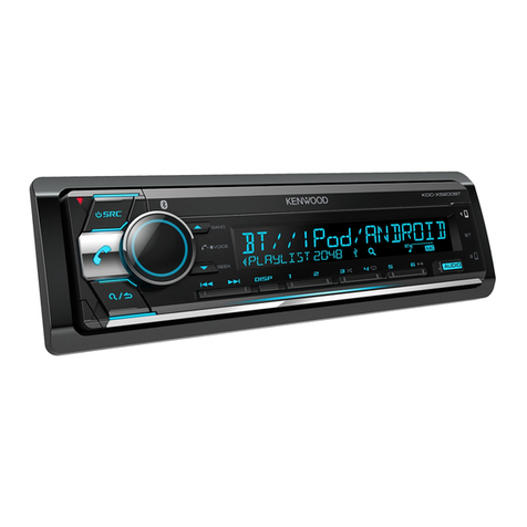
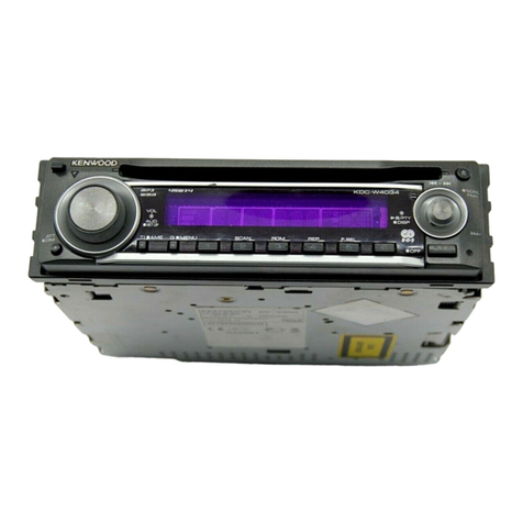
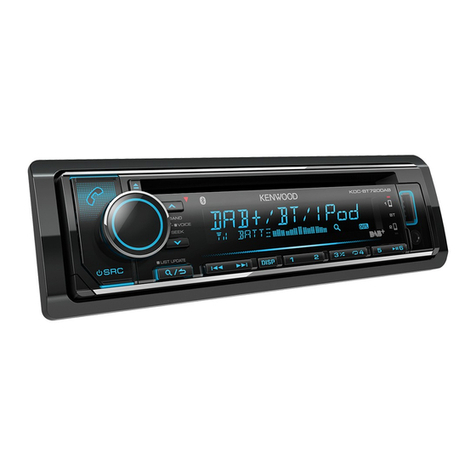
Kenwood KDC-719 User manual

Kenwood

Kenwood KDC-719 User manual

Kenwood KVT-829DVD User manual

Kenwood

Kenwood KVT-829DVD User manual

Kenwood KDC-X859 User manual

Kenwood

Kenwood KDC-X859 User manual

Kenwood KDC-MP6090R User manual

Kenwood

Kenwood KDC-MP6090R User manual

Kenwood DPX501 User manual

Kenwood

Kenwood DPX501 User manual

Kenwood KRC-803 User manual

Kenwood

Kenwood KRC-803 User manual

Kenwood DPX-3070 User manual

Kenwood

Kenwood DPX-3070 User manual

Kenwood DPX-4010 User manual

Kenwood

Kenwood DPX-4010 User manual

Kenwood KDC-MP245 User manual

Kenwood

Kenwood KDC-MP245 User manual

Kenwood DPX-6020 User manual

Kenwood

Kenwood DPX-6020 User manual

Kenwood DDX7035BT User manual

Kenwood

Kenwood DDX7035BT User manual

Kenwood KDC-7027Y User manual

Kenwood

Kenwood KDC-7027Y User manual

Kenwood KDC-3028 User manual

Kenwood

Kenwood KDC-3028 User manual

Kenwood KDC-X399 User manual

Kenwood

Kenwood KDC-X399 User manual

Kenwood KRC-478R/RV User manual

Kenwood

Kenwood KRC-478R/RV User manual

Kenwood KRC-335 User manual

Kenwood

Kenwood KRC-335 User manual

Kenwood DPX501U User manual

Kenwood

Kenwood DPX501U User manual

Kenwood KDC-X8016BT User manual

Kenwood

Kenwood KDC-X8016BT User manual

Kenwood KMM-BT407DAB User manual

Kenwood

Kenwood KMM-BT407DAB User manual

Kenwood KDC-7080R/RV User manual

Kenwood

Kenwood KDC-7080R/RV User manual

Kenwood KRC-104 User manual

Kenwood

Kenwood KRC-104 User manual

Kenwood DDX795 User manual

Kenwood

Kenwood DDX795 User manual

Kenwood KDC-BT60U User manual

Kenwood

Kenwood KDC-BT60U User manual

Kenwood DPX-5100BT User manual

Kenwood

Kenwood DPX-5100BT User manual

Popular Car Receiver manuals by other brands

Linear Series LS5050 Operation and installation manual

Linear Series

Linear Series LS5050 Operation and installation manual

Sony XR-CA430X Service manual

Sony

Sony XR-CA430X Service manual

T+A Elektroakustik K1 CD-RECEIVER operating instructions

T+A Elektroakustik

T+A Elektroakustik K1 CD-RECEIVER operating instructions

SoundMax SM-CDM1052 instruction manual

SoundMax

SoundMax SM-CDM1052 instruction manual

Xtrons HD107HD user manual

Xtrons

Xtrons HD107HD user manual

Mopar RB3 manual

Mopar

Mopar RB3 manual

Clarion ADDZEST DMZ615 owner's manual

Clarion

Clarion ADDZEST DMZ615 owner's manual

Sony XAV-601BT Specifications

Sony

Sony XAV-601BT Specifications

PIE GM12-POD/S Operation manual

PIE

PIE GM12-POD/S Operation manual

Hyundai H-910H instruction manual

Hyundai

Hyundai H-910H instruction manual

Sony XR-C6100 Service manual

Sony

Sony XR-C6100 Service manual

Sony CDX-L600X - Fm/am Compact Disc Player Installation/connections

Sony

Sony CDX-L600X - Fm/am Compact Disc Player Installation/connections

Motorola VWA63 Service manual

Motorola

Motorola VWA63 Service manual

Sound Storm STM93R user manual

Sound Storm

Sound Storm STM93R user manual

Nextar D3201 instruction manual

Nextar

Nextar D3201 instruction manual

Alpine CDE-163BT owner's manual

Alpine

Alpine CDE-163BT owner's manual

Axxera XDMA7600 Installation & owner's manual

Axxera

Axxera XDMA7600 Installation & owner's manual

XM OnyX quick start guide

XM

XM OnyX quick start guide

manuals.online logo
manuals.online logoBrands
  • About & Mission
  • Contact us
  • Privacy Policy
  • Terms and Conditions

Copyright 2025 Manuals.Online. All Rights Reserved.

KENWOOD
KRC-535
SIRIUS
Satellite Radio
CASSETTE RECEIVER
INSTRUCTION MANUAL
~ AMPLI-TUNER-LECTEUR DE CASSETTE
MODE D’EMPLOI
~ RADIO CASSETTE
i MANUAL DE INSTRUCCIONES
KENWOOD CORPORATION
Take the time to read through this instruction manual.
Familiarity with installation and operation procedures will help you obtain the
best performance from your new cassette-receiver.
For your records
Record the serial number, found on the back of the unit, in the spaces designated on
the warranty card, and in the space provided below. Refer to the model and serial
numbers whenever you call upon your KENWOOD dealer for information or service on
the product.
Model KRC-535 Serial number
@B64-2154-00 (KW) so
iafety precautions ..........-........ 3
Lbout Cassette tape ...................4
ieneral features .........................5
Power
Selecting the Source
Volume
Attenuator
Loudness
System Q
Audio Control
Speaker Setting
Switching Display
Switching Clock Display
Station/Disc Naming (SNPS/DNPS)
Auxiliary Input Display Setting
Faceplate Angle Adjustment
Theft Deterrent Faceplate
Hiding the Control Panel
Tuner features ........................... 10
Tuning Mode
Tuning
Direct Access Tuning
Station Preset Memory
Auto Memory Entry
Preset Tuning
Zassette player features ....-... 12
Playing Cassette Tapes
Fast Forwarding and Rewinding
Dolby B NR
Selecting the Tape type
DPSS (Direct Program Search System)
DPSS with the Remote
Blank Skip
Music Repeat
External disc control features.. 15
Playing External Disc
Fast Forwarding and Reversing
Track Search
Album Search
Direct Track Search
Direct Album Search
Track/Album Repeat
Track Scan
Random Play
Magazine Random Play
Text/Title Scroll
DNPP (Disc Name Preset Play)
Menu system ............................-16
Menu System
Security Code
Touch Sensor Tone
Manual Clock Adjustment
Selectable Illumination
Switching Graphic Display
Contrast Adjustment
Dimmer
OFF Wait Time Setting
CRSC (Clean Reception System Circuit)
Text Scroll
Basic Operations of remote......22
Loading and Replacing the battery
Basic operations
In Tuner source
In Cassette tape source
In Disc source
Accessories ...............................24
Installation Procedure ..............24
Connecting Wires to Terminals ...
................................................25
Installation (nonJapanese cars) ..
................................................26
Installation (Japanese cars) .....26
Removing the Unit ................-27
Locking the faceplate to the unit
................................................27
Troubleshooting Guide .............26
Specifications ...........................31
-2-
To prevent injury or fire, take the
following precautions:
l Insert the unit all the way In until it is fully
locked in place. Otherwise it may fall out of
place when jolted.
l When extending the ignition, battery, or
ground wires, make sure to use automotrve-
grade wires or other wires with a 0.75mmz
(AWG 18) or more to prevent wire
deterioration and damage to the wire
coating.
l To prevent a short circuit, never put or leave
any metallic objects (such as coins or metal
tools) insrde the unit.
l If the unit starts to emit smoke or strange
smells, turn off the power immediately and
consult your Kenwood dealer.
* Make sure not to get your fingers caught
between the faceplate and the unit.
l Be careful not to drop the unit or subject it to
strong shock.
The unrt may break or crack because it
contains glass parts.
l Do not touch the liquid crystal fluid if the
LCD is damaged or broken due to shock. The
liquid crystal fluid may be dangerous to your
health or even fatal.
If the liquid crystal fluid from the LCD
contacts your body or clothing, wash it off
with soap immediately.
1ACAUTION 1
To prevent damage to the machine,
take the following precautions:
l Make sure to ground the unit to a negative
12V DC power supply.
l Do not open the top or bottom covers of the
unit.
l Do not install the unit in a spot exposed to
direct sunlight or excessrve heat or humidity.
Also avoid places with too much dust or the
possibility of water splashing.
l Do not subject the faceplate to excessive
shock, as it is a piece of precision
equipment.
l When replacing a fuse, only use a new one
with the prescribed ratrng. Using a fuse with
the wrong rating may cause your unit to
malfunction.
l To prevent a short circuit when replacing a
fuse, first disconnect the wiring harness.
l Do not place any object between the
faceplate and the unit.
l Do not use your own screws. Use only the
screws provided. If you use the wrong
screws, you could damage the unrt
l Do not apply excessrve force to the movrng
faceplate. Dorng so WIII cause damage or
malfunctron.
l Do not apply excessive force to the open
faceplate or place objects on it. Doing so will
cause damage or breakdown.
IMPORTANT INFORMATION
About the disc changer/CD player to
be connected:
To connect a disc changer having the “O-N”
switch to this unit, set the “O-N” switch to “N”.
When you connect a model with no “O-N”
switch, the converter cord CA-DSIOO available
as an option may be required. For details,
consult your Kenwood dealer.
A disc changer doesn’t work when it is
connected without using these options.
If a model with no “O-N” switch is connected,
some unavailable functions and information
that cannot be displayed are generated.
Note that none of the KDC-CIOO, KDC-C302,
C205, C705, and non-Kenwood CD changers
can be connected.
A Youcan damage both your unit
and the CD
changerIf you connect them Incorrectly.
If the following situations, consult
your nearest service center:
l Eventhough the disc changer ISconnected, the
DISCChangersource
is not ON, with “AUX”
showng In the
drsplay during the Changer Mode.
l
Even though no device (KCA-S210A. CA-ClAX,
KDC-CPS87, KDC-CX87, KDC-CPS85, KDC-CX85,
KDC-CPS82 or KDC-CX82) IS connected, the
Awllay Input is entered when swtchlng modes
“Dolby” and the double-D symbol are
of Do/by Laboratories.
-3-
Ifperience problems during
installation, consult your Kenwood dealer.
l If the unit fails to operate properly, press the
Reset button. The unit returns to factory
settings when the Reset button is pressed.
If the unit still fails to operate properly after
the Reset button has been pressed, contact
your local KENWOOD dealer for assistance.
l Press the reset button if the disc auto
changer fails to operate correctly. Normal
operation should be restored.
Reset-button
l We recommend the use of the Security
Code function (see p.18) to prevent theft.
l Characters in the LCD may become difficult
to read in temperatures below 41 “F (5 ‘C).
l The illustrations of the display and the panel
appearing in this manual are examples used
to explain more clearly how the controls are
used. Therefore, what appears on the display
in the illustrations may differ from what
appears on the display on the actual
equipment, and some of the illustrations on
the display may represent something
impossible in actual operation.
Cleaning the &cap/ate Terminals
If the terminals on the unit or faceplate get
drrty, wipe them with a dry, soft cloth.
Cleaning the Unit
If the faceplate of this unit is stained, wipe it
with a dry soft cloth such as a silicon cloth.
If the faceplate is stained badly, wipe the stain
off with a cloth moistened with neutral
cleaner, then wipe neutral detergent off.
@ Applyrngspraycleanerdirectly to the unrt may
affect Its mechanrcalparts. Wiping the
faceplate with a hardcloth or using a volatrle
liquid such as thinner or alcohol may scratch
the surface or erases characters.
Cleaning the tape head
When there’s noise or the sound quality is bad
during tape play the tape head maybe dirty,
clean the tape head.
About Cassette tape
l If the tape ISslack tighten it.
l If the cassette tape label is peeling off glue it
on again.
l Don’t use deformed cassette tape.
l Don’t place cassette tape on the dashboard
etc. where the temperature IS high.
l Don’t use cassette tape that’s 100 minutes
long or longer.
-A-
SRC/
PWROFFAM FM ANG Cl
I I II
+ Ail/ CLK
LOUD NAME.S
SYSTEM
0 indicator
ATT
indicator
JO Turning ON the Power
Press the [SRCI button.
Turning OFF the Power
Press the [SRCI button for at least 1 second.
Clockindicator SpeakerSettingindicator
Press the [SRCI button.
Source required
Tuner
Tape
Display
“TUNER”
“TAPE”
External disc
Auxiliary input
Standby (Illumination only mode)
“DISC”
“AUX”
“ALL OFF”
For Auxlllary Input one of the below optional accessones IS
necessary.
KCA-S21OA
CA-C1AX
CD changer with an Auxlllary input function mstalled.
-5-
Increasing Volume
Press the [A] button.
Decreasing Volume
Press the [VI button.
General features
Press the IQ1 button.
Each time the button is pressed the sound setting switches.
Sound setting Display
Flat “Flat”
Rock
Top 40 “Rock”
“Top 40”
Jazz “Jazz”
Easy “Easy”
Scan of Flat - Easy “Scan”
User memory “User”
l User memory. The values set on the <Audio contrcr>
(Page 6).
utton IS pressed the Attenuator turns ON or OFF. @ l Eachsettrng value ISchangedwrth the <Speakersettrng> (Page
When It’s ON, the “ATT” indicator blinks. 7).
First, select
the speaker type with the
Speaker
settW
Press the [LOUD] button for at least 1 second.
Each time the button is pressed for at least 1 second the
Loudness turns ON or OFF.
When it’s ON, “LOUD ON” is displayed.
You can recall the best sound setting preset for different types off
the music.
1
Select the source to set
Press the [SKI button.
2 Select the Sound type
-6
1
Select the source for adjustment
Press the KSRCI button.
2 Enter Audio Control mode
Press the [AUDI button for at least 1 second.
3 Select the Audio item for adjustment
Press the [FM1 or [AMI button.
Each time the button is pressed the items that can be adjusted
switch as shown below.
4 Adjust the Audio item
Press the [WI or [WI button.
Adjustment Item Display Range
Bass level “Bass” -8 - +8
Middle level “Middle” -8 - +8
-
Treble level
Balance
Fader
“Treble”
“Balance”
“Fader’
-a - +8
Left 15 - Right 15
Rear 15 - Front 15
Volume offset “V Offset” -8--O
@ Volume offset: Eachsource’s volume can be set as a drfference
from the bastevolume.
5 Exit Audio Control mode
Press the [AUDI button.
Fine-tuning so that the System Q value is optimal when setting
the speaker type.
1
Enter Standby
Press the [SRCI button.
Select the “ALL OFF” display.
2 Enter Speaker Setting mode
Press the [QI button.
3 Select the Speaker type
Press the [I-] or [)H] button.
Each time the button ISpressed the setting switches as shown
below.
Speaker type Display
OFF “SP OFF”
For 6 & 6x9 in. speaker “SP 6*9/6inch”
For 5 & 4 in. speaker
For the OEM speaker “SP 5/4inch”
“SP O.E.M.”
4 Exit Speaker Setting mode
Press the [QI button.
Switching the information displayed.
Press the [DISPI button.
Each time the button is pressed the display switches as shown
below.
In Tuner source
Information
Frequency
Station name
In Tape source
Information
Play side & Tape counter
Play side & Tape running
Play side
In External disc source
Information
Track Time
Disc name
Disc title
Track trtle
Display
“SNPS”
Display
“DNPS”
“D-TITLE”
“T-TITLE”
Switching the displayed information.
Press the [CLKI button.
Each time the button ISpressed It switches between clock
display and current source.
During clock display the clock rndrcator IS ON
Attaching a title to a Station or CD.
1
Receive/play the station/disc you want to attach a title to
@ l
A title can’t be attached to a MD.
l
DISCNaming can’t be done during CD text display.
2 Enter name set mode
Press the [NAMES] button for at least 2 seconds.
“NAME SET” is displayed.
3 Move the cursor to the enter character position
Press the [1441 or [WH] button.
4 Select the character type
Press the [~II] button.
Each time the button is pressed the character type switches as
shown below.
Character type
Alphabet upper case
Alphabet lower case
Numbers and symbols
Special characters (Accent characters)
5 Select the characters
Press the [FM] or [AM] button.
@
Characters can be entered by using a remote wth a number
buttons
Example: If “DANCE” ISentered.
Character Button #Times pressed
“D” 1#31 1
“A” [#21 1
“N”
Ml
2
“C”
Pa
3
“E” I#31 2
6
Repeat steps 3 through 5 and enter the name.
7 Exit name set mode
Press the [NAME.SI button.
@ l
When operation stops for 10 seconds the name at that time IS
reglstered, and Name Set mode
closes.
l
Memory numbers
FM: 32 stations
AM: 16 stations
External CD changer/ player: Vanes according to the CD changer/
player. Refer to the CD changer/ player manual.
l
The title of station/CD can be changed by the same operation
used to name It.
Selecting the display when this device is switched to Auxiliary
input source.
1
Select Auxiliary input source
Press the [SRCI button.
Select the “AUX” display.
2 Enter Auxiliary input display setting mode
Press the [NAME.Sl button for at least 2 seconds.
The presently selected AUX Name is displayed.
3-
3 Select the Auxiliary input display
Press the [WI or [WI button.
Each time the button is pressed it switches through the below
displays.
. “AUX”
. “TV”
. “VCP”
. “GAME”
l
“PORTABLE”
4 Exit Auxiliary input display setting mode
Press the [NAME.SI button.
@
When operation stops for 10 seconds, the name at that time IS
selected, and Auxlllary Input display setting mode closes.
Press the [ANGI button for at least 1 second.
@ l
Do not apply excessive force to the faceplate. It can cause
damage.
l
The faceplate angle cannot be adjusted during tape play.
The faceplate of the unit can be detached and taken with you,
helping to deter theft.
Removing the Faceplate
1
Turn the ignition OFF or press the [SRCI button for at least 1
second.
The power turns OFF and the faceplate slides open
2 Holding the center part of the faceplate pull it out.
A
l
When the faceplate ISkept remove open, according to the <OFF
Walt Time Setting> (page 21) setting, the feceplate IShldden and
the power turns OFF
l
The faceplate ISa precision piece of equipment and can be
damaged by shocks or jolts. For that reason, keep the faceplate In
Its spew storage case while detached.
l
Do not expose the faceplate or Its storage case to direct sunllght
or exceswe heat or humldlty. Also avold places with too much
dust or the possMlty of water splashing.
Reattaching the Faceplate
1
Set the left side of the faceplate in the faceolate bracket.
2 Press the right side of the faceplate until it locks.
General features Tuner features
Prevents tampering with the unit while your car is being serviced
etc.
Hiding the control panel
Press the [SRCI button for at least 1 second.
The faceplate slides open.
When the time set In <OFF Walt Time Setting> (page 21) lapses,
the faceplate is hidden and the power turns OFF.
Showing the control panel
Press the left part at the upper side of the faceplate.
The faceplate WIII open and show the control panel.
AM FM SRC
#i-6
AUTO/ MENU
AME
Banddisplay
I Frequencydisplay Presetstationnumber
I I
STindicator
-lO-