Os
eae
st
RL
CE
er
sn
ree
rs
ef
hn
nse
Contents
Before
use
MIE
EN
sitet
cate
co
seas
tni
cgassien
us
Sheh
taecttlehanenpenaneanneameiasea
3
SAICLYy
PIOCAN
ONS
13.46
natn
cn
votch
naetustacesenenssedinee
ations
4
BUUONS
SAMOS
DISDIAY
ic
srraatsdentinkudiereman
tiene
menawe
nia
6
Basic
operations
ON
acti
ge
ope
traci
aa
apas
ceshoeseceh
beast
nam
eae
ee
8
SW
IMETING:
ORGS
acacia
ces
secre
td
aae
cp
aeaunamnncoeuetteaies
8
MONIC
cisces
et
otek
htt
ht
Asa
tesceals
ticle
glee
eietaioa
te
deeas
et
tialat
8
PUM
GUON
ecclesia
caristnccaia
savanna
Mentn
scammed
8
PO
UOINC
S35
sp
sis
etic
iced
stk
tadsaan
sew
statin
ava
te
aeannenatdeaate
8
Tuner
features
BAU
ig
|]
6)
9
peer
eres
eee
ie
ee
ne
eT
OE
ne
ae
een
see
g
Station
Preset
MeMOry
scwirtiniaidonaiaue
teem
ert
9
AUTO
MIGIMIORY
EMU
visi
sccicsacacdsrasics
mceeesyavintendahavieniecsatione
9
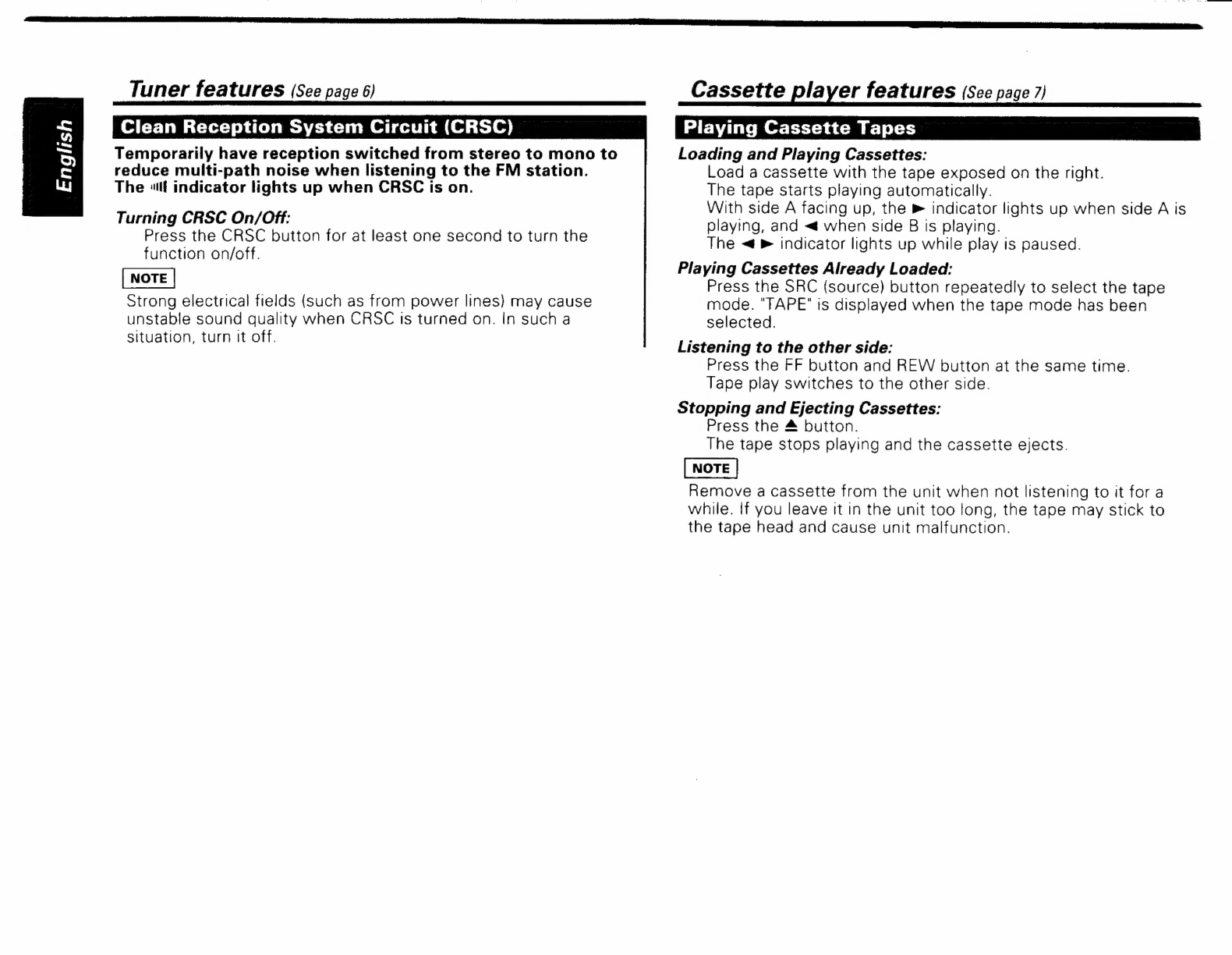
Clean
Reception
System
Circuit
(CRSC)
.......
10
Cassette
player
features
Playing
Cassette
Tapes
.0.....0ccccccccesestesterteneesererees
10
Fast
Forwarding
and
Rewinding
Cassette
Tapes............
11
US
=1
ap
OX:
||
Mean
epeeree
Cece
eee
Cnn
Mette
ain
Rt
tee
fone
aE
en
11
Other
features
AUGIO
CORIO
SS
UUING
oi
sida
wiceestctcus
tear
nactaddavaeecameenes
12
ClOCR
DIS
BIA
Yo
iittieviccteescousiyytie
vuitdeoiioadutrewtescaieadsteder
hdactiann
IZ
PHOS
EUG
WAG:
eet
Hiatt
tein
caesun
laser
oecsaceamleteadadrdocedte
iz
Installation
|
PROCS
SS
ONO
S
sco
5s
tra
cre
lonern
ctw
din
doranc
case
eeeecitieicidasiewialoes
13
|
ISTE
SHON
FrOCEGUIC
ain
tent
dnwddncl
cana
bia
in
rtaedea
ete
tedt
atieee
13}
Connecting
Wires
to
Terminals
............cccccecesecsesececeeeeeeeee
14]
(STAN
AOR
xetereeiccuivanc
teeta
Racca
dihusiusnd
at
amicus
machete:
15
|
Troubleshooting
Guide
........................0..ccccccccccccccceeess
17
|
Specifications
oo
cccccccccccecsseeccceeeeeeneens
18
|