manuals.online logo
Brands
  1. Home
  2. •
  3. Brands
  4. •
  5. Kenwood
  6. •
  7. Cassette Player
  8. •
  9. Kenwood KX-4520 User manual

Kenwood KX-4520 User manual

|
SERV.
29H
YZ
STEREO
CASSETTE
DECK
Knob(EJECT)
(K29-3807-04)
Knob
(POWER)
{K29-3805-04)
Foot
KX-4520
SERVICE
MANUAL
Cassette
lid
ass’y
(A53-)
GTENEG
GASMITTE
DESK
Kx-a5R0
Dressing
plate
(B50-)
(JO2-
1002-05)
x
Phono
jack
(E13-0482-05)
|
04
KENWOOD
©1989-10
PRINTED
IN
JAPAN
B51-3904-00(B)3301
-
Knob
(REC
LEVEL)
(K29-3804-04)
*
Panel
ass’y
(A20-5919-03)
Remote
control
ass’y
is
Knob
(A70-03
17-05)
(K27-2003-04)
x3
*
AC
inlet
(M
type
only)
(E03-0102-25)
cso
ORE
aR
ek
sem
meacseN
Miniature
phone
(SYSTEM
CONTROL)
(E11-0188-05)
*Refer
to
parts
list
on
page
42.
KX-4520
CONTENTS
CONTROL
AND
INDICATORS.........---------+-555
2
PC
BOARD
(Component
Side
View)
DISASSEMBLY
FOR
REPAIR.....-.-.-----++--
+2005
3
PC
BOARD
(Foil
Side
View)
........
BLOCK
LEVEL
DIAGRAM........-.--..-
2-02
e
sree
eee
5
SCHEMATIC
DIAGRAM
........-..--
CIRCUIT
DESCRIPTION
........---.
02.
eee
eee
renee
6
EXPLODED
VIEW
(MECHANISM)...
MECHANISM
DESCRIPTION.........-.----.--
eee
ee
20
EXPLODED
VIEW
(UNIT)
.........-.
ADJUSTMENT
........2
00
e
cece
cece
enter
eens
22
PARTS
LIST
........
002
eee
eee
ee
eee
REGLAGE
225.08
Soe
et
B
ot
eSNG
heme
Lee
Yee
23
SPECIFICATIONS
.......-.--.--005>
ABGLEICH
3.0.5.
ccc.
cc
pet
ese
tine
0a
sede
gat
oe
oe
te
24
CONTROL
AND
INDICATORS
TAPE/SOURCE
indicators
1
‘
AUTO
BIAS
indicator
PEAK
LEVEL
METER
Operation
indicators
SNTERT!
DOLBY
7
ray
GOUNTER
1)
OMBY
|
ip
me
so
2015
10
7
SB
2
1
0
1
FS
7
OB
1
OO
ence,
Tape
position
indicators
DOLBY
NR
indicators
Display
window
MULTLWAY
COUNTER
CCAS
key
—~\
COUNTER
RESET
key
AUTO
BIAS
key
Eject
key
TAPE/SOURCE
selector
(MONITOR)
key
REC/ARM
PAUSE
key
PAUSE
key
fi
REC
LEVEL
control
knob
Remote
contro!
light
receptor
REC
BALANCE
control
knob
PHONES
LEVEL
control
knob
PHONES
jack
Cassette
holder
Rewind
key
Te}
TIMER
switch
Fast
forward
key
[>>)
Play
key
co
POWER
switch
MPX
FILTER
switch
Stop
k
op
ney
DOLBY
NR
switches
ON/OFF
switch
B/C
selector
switch
Note
on
counter’s
preciseness
The
Jinear
tape
counter
used
with
this
unit
is
not
a
clock,
and
there
is
a
certain
error
between
the
displayed
time
and
real
recording
time
{this
is
un-
avoidable
because
this
unit
has
been
designed
to
be
capable
of
displaying
tape
time
also
during
fast
forward
and
rewind
operations
as
well
as
during
recording
and
playback).
The
degree
of
this
error
is
dependent
on
the
type
of
tape.
om
“*
Take
out
the
case
in
advance.
1.
2.
ONOARW
9.
10.
Remove
the
three
screws
@.
11.
Undo
the
four
catches
()
.
and
disconnect
the
board.
KX-4520
BLOCK
LEVEL
DIAGRAM
Remove
the
five
screws
:
Undo
the
three
catches
,
and
detach
the
front
pan-
el.
Remove
the
three
knobs
and
two
nuts
@.
Remove
the
two
screws
@.
Cut
the
two
convexes
eS
:
Disconnect
the
eight
connectors
6)
.
Unground
@.
Undo
the
two
catches
at
the
both
sides,
and
detach
the
sub
panel
©.
Remove
the
two
screws
@
.
and
detach
the
shield
plate.
KX-4520
DISASSEMBLY
FOR
REPAIR
12.
Press
the
eject
button
to
open
the
cassette
holder
@.
13.
Setaside
the
eject
lever
to
the
left
side
®.
(When
detaching,
draw
it
out
in
the
upper
left
direc-
tion)
14.
Remove
the
four
screws
@
.
and
take
out
the
mecha-
nism.
15.
Disconnect
the
board
(X26)
(B/2)
®.
16.
Remove
the
seven
screws
;
17.
Disconnect
the
connector
.
18.
Draw
up
the
board
together
with
the
rear
panel
rear-
wards.
19.
When
detaching
the
knob
of
the
power
switch,
open
slightly
the
portion
indicated
by
arrows
using
a
lead
punch,
etc.
KX-4520
i
i
|
Yy39N3S
Wv>
[QION3
105
|
YOLOW
NvilSd
VD
YOLOW
t
1334
a=
1
Y39NAS
advil
waONSS
O10Hd
[
Si
ol
SAtHG
BLOCK
LEVEL
DIAGRAM
he:
OYHONAS
@—O
MI]
Aen
ss
(Sz2x)
13)
asna’s[’
|
oe
td
(S2x)
vO
O<]
Db.
413S3u
cy!
ZHHOO
voOG
vov
VOE
“oauP(isst)
[ston
|
uxssxfavid
if
“33471
7019
x
at
zu
uy
Oo”
SERS,
tte,
woo-
zi
91
cart!
AVNdS!d0
V4
edoe~l1/V9OS~!
€~Ou
y¥/7
LAANI
3
RO,
i/S-Hd
svia
Binw
934y
.
aLnW
3N14
43S3y
@1S/x19/
VLA
9G~eS0
(
[>o
)
IBEW
/SNOZ
XIULUN
v
KAM
440/NO
487100
g@/>
Ag100
‘MS
SVIG
3LNW
944
31INW
3NI7
Qv'Spo'piat
13534
prisvid
2W
7/197
ON
SOYHNOS
/3dVL
3N1I7/2S0
ZHAO!
/
OOv
v
£
24£~vE0
=e
6e
eco
Ee)
‘Q'd
2plvo
ms
“NIVO
4H9!7
WOVE
Av1dS!iQ
14
13$34
4Y3SN3S
O10Hd
“"WOO-.
JLOWAY
“woo-"
AS+
hy
(VHOAW)
“MS
yY3MOd
YOLOW
NVLSdV9
F
YOLOW
13344
Adl
+
“dWVY
JNOHd
“dwy
907
“dWV
Y3L3W
°03°93a
“O3'8'd
A8@100°
39348
A8100'8'd
gz2‘120
3Lnw’
934
aLnw
aniiPaspK
YAY
(dNV
34d
ASF
“rav
svie
(74s
advi
“13S°03/°MS‘03
ie
‘Bd
49100
“MS
HYOLINOW
>
(d/4)
AB10G
'93y
<<]
JLAW'9SO
NAO/AZS'
$30
“cay
"Ol
y3L3W
}+—_—0_
2-0
YAU
Sd
oso
Ace
key
o
asvu3
(2H4012)
aeesalc]
‘MS
vig
)
S2'p20®,
221
‘nas
|
8501
-ms
3BdVL
svig
99
MW)
gI~E10
zit'io
“3S
62
2LNW
03
3°
94y
om.
ovat
>
oy
o
“O34
‘OA
dv
‘334
svlga
Osd
XH
ol'6o
LOW
9)
7590
Sol
3NIT
Kd
7
[ae
"348"
tz‘oz2o
MSI
610
-|
ddt
31LNW
SNOL
“oso
ASSL
OvOKy
MS
BD
NiVS
felmel]
KJ
<]
‘dwWY
907
“dWv
yaLan
eittem,
YY
oa
€3l
K
aa
(a)
ae
5
Ag100
dvul
‘a'd
Svla
“MS
y¥Oi1
INOW
AO,
KX-4520
CIRCUIT
DESCRIPTION
Description
of
component
Cassette
unit
(X26-1240-00)
Use/function
Operation/condition/compatibility
28C1740S
(Q,
R)
Playback
EQ
time
constant
Selects
between
120
psec
and
70
usec
of
playback
EQ
high-frequency
time
constants!
2SC945
(A)
(Q,
P
selection
switch
nee
i
[tape
_[an.2
|
Tine
constant
|
Normal
3180~120
(psec)
Chrome
3180~
70
(usec)
Metal
3180~
70
(usec)
2SC2878
(B)
Line
mute
switch
For
recording
or
playing
source,
the
pin
10
(LM)
of
microprocessor
1C12
becomes
“H”
2SD1302
(S,
T)
and
044
thereby
turns
OFF
so
that
03
and
Q4
turn
OFF.
REC
-
PLAY
-
SOURCE
OTHER
2SC1740S
(Q,
R)
MPxX
filter
switch
An
“H"
or
“L”
signal
is
output
according
to
the
“ON”
or
“OFF”
operation
of
the
MPX
2SC945
(A)
(Q,
P)
filter
switch
(S1-C/3:
X25-3770
system)
so
that
Q5~Q8
turn
ON
or
OFF.
When
Q5~Q8
turn
ON,
the
MPX
filter
works.
2SC2878
(B)
Recording
mute
switch
For
recording,
the
pin
171
(RM)
of
microprocessor
1C12
becomes
“H”
and
Q43
thereby
2SD1302
(S,
T)
turns
OFF
so
that
Q9~Q12
turn
OFF.
Q13,
14
2SC1740S
(Q,
R)
Recording
EQ
chrome
switch
When
a
chrome
tape
is
loaded,
the
pin
10
(C)
of
extension
IC
1C13
becomes
“L”
and
2SC945
(A)
(Q,
P)
Q32
thereby
turns
ON
so
that
Q13
and
Q14
turn
ON.
Q15,
16
2SC1740S
(Q,
R)
Recording
EQ
metal
switch
2SC945
(A)
(Q,
P)
Q17,
18
2S8C17408S
(Q,
R)
Recording
EQ
peaking
selection
When
a
normal
tape
is
loaded,
the
pin
11
(N)
of
extension
IC
IC13
becomes
“L"
and
2SC945
(A)
(Q,
P}
switch
Q31
thereby
turns
ON,
while
when
a
chrome
tape
is
loaded
Q32
turns
ON
in
the
same
process,
so
that,
either
way,
Q17
and
Q18
turn
ON
through
a
diode
matrix
D5
Q19
2SC1740S
(Q,
R)
Test
signal
mute
switch
For
AUTO
BIAS
operation,
the
pin
5
(O/L)
of
extension
IC
1C13
becomes
"L”
and
Q19
2SC945
(A)
(Q,
P)
thereby
turns
OFF
to
pass
the
test
signal.
i
Except
for
AUTO
BIAS
operation,
Q19
is
ON.
Q20,
21
2SC1740S
(Q,
R)
Test
signal
filter
cutoff
frequency
For
AUTO
BIAS
operation,
selects
between
cutoff
frequencies
in
synchronization
with
2SC945
(A)
(Q,
P)
selection
switch
the
test
signal
frequency.
Fraguenc
400/10k
IC13
Fenuency
pin
6
Except
for
AUTO
BIAS
operation,
Q20
and
Q21
are
OFF.
2SD863
(E,
F)
Erase
head
excitation
For
recording,
a
push-pull
oscillation
is
made
at
f=210
kHz
to
flow
the
erase
current
and
the
bias
current.
28C3246
BIAS+B
ON/OFF
switch
For
recording,
the
pin
25
(BIAS)
of
microprocessor
|C12
becomes
“H”
and
Q30
thereby
;
turns
OFF
and
Q25
OFF
so
that
Q24
turns
ON
to
apply
+B
to
the
erase
oscillator
and
the
HX
excitation
coil.
025
|
ass
|
az24
OFF
|
OFF
ON
ON
ON
OFF
o
DTC124ES
Bias
ON/OFF
switch
For
recording,
Q25
turns
OFF
to
let
the
bias
ON.
aa
Name
DTA124ES
ne
RISER
Orne
TELS
MRO
aE
OREO
SS
SRST
TY
DTC
~KX-4520
CIRCUIT
DESCRIPTION
Use/function
Operation/condition/compatibility
Bias
step
driver
For
AUTO
BIAS
operation,
the
bias
current
is
varied
to
correct
the
tape
recording/playback
frequency
response.
(MAX.
16
steps)
Due
to
the
“H’/"L”
action
of
the
pins
1~4
(B1~B4)}
of
extension
IC
1C13,
transistors
Q26~Q29
turn
OFF/ON
so
that
the
transistor
of
IC8
turn
OFF/ON
to
vary
the
bias
current.
Extension
IC
(1C13)
Driver
ATT
switch
(IC8)
B4
(P4):
H/L
Q29:
OF/ON
INVERTER
1:
OFF/ON
B3
(P3):
H/L
Q28:
OF/ON
INVERTER
2:
OFF/ON
B2
(P2):
H/L
Q27:
OF/ON
"INVERTER
3:
OFF/ON
Bi
(P1):
H/L
Q26:
OF/ON
INVERTER
4:
OFF/ON
Initial
value
B4—"L"
Q29=ON
INVERTER
1=ON
B1~3=—="H"
Q26~28-OFF
INVERTER
2~4—OFF
oe
Q30
2SA733
(A)
(Q,
P)
Bias
ON/OFF
driver
2SA933S
(Q,
R)
Q31~33
034,
36
DTA124ES
DTA124ES
DTA124ES
DTA124ES
Refer
to
the
pertinent
description
under
Q24.
Tape
selector
driver
DOLBY
NR
mode
selection
switch
Tape/source
selection
control
DTC124ES
Extension
IC
(IC12)
N
(pin
11)
|
C
(pin
10)
|
M
(pin
9)
Q31
Normal
H H
ON
Chrome
L
H
OFF
Metal
H
OFF
Due
to
the
“H"/"L"
action
of
pins
11
(N),
10
(C)
or
9
(M)
of
extension
IC
IC13
depending
upon
the
tape
loaded
on
the
deck,
the
tape
selector
driver's
Q31,
Q32
or
Q33
turns
ON
for
a
normal,
chrome
or
metal
tape,
respectively.
To
provide
the
DOLBY
noise
reduction
mode
selected
by
the
DOLBY
NR
ON/OFF
and
B/C
switches
(S1-a/3,
b/3:
X25-3770
system),
due
to
the
“H"/*L"
action
of
the
pin
8
(DOLBY
ON/OFF)
of
extension
IC
IC13,
Q36
and
037
turn
OFF/ON,
while
due
to
the
“H"/“L"
action
of
the
pin
7
(DOLBY
C/B),
Q34
and
Q35
turn
OFF/ON.
Thus,
the
DOLBY
noise
reduction
mode
is
determined
by
"H’/“L”
combination.
poisy
|
powey
on/OFF
|
ooieye7S
[ase
|
axe
[ae
[oar
OFF
L
L
OFF
|
OFF
|
ON
|
ON
B
H
L
OFF
|
OFF
|
OFF
|
OFF
c
H
H
ON
|
ON
|
OFF
|
OFF
Due
to
the
“L"/"H"
action
of
the
pin
9
(T/S)
of
extension
IC
IC13,
Q38
and
Q39
turn
ON/OFF
to
apply
an
“H’/"L”
signal
to
the
control
pin
of
monitor
selection
analog
switch
IC3.
MODE
T/s
038 039
IC3
Pins.12
and
13
of
IC3
TAPE
L
ON
ON
BV
sv
SOURCE
H
OFF
OFF
-8V
BV
Q40
25C1740S
(Q,
R)
Meter
amplifier
gain
selection
switch
{
For
AUTO
BIAS
operation,
Q40
turns
ON
to
raise
the
meter
amplifier
R-ch
gain.
The
AUTO
BIAS
test
signal
(—20
VU)
is
thus
amplified
for
easier
microprocessor
level
discrimination.
Except
for
AUTO
BIAS
operation,
Q40
is
OFF.
2SC945
(A)
(Q,
P)
Q41
DAT124ES
Test
signal/line
signal
selection
driver
For
AUTO
BIAS
operation,
the
pin
5
(O/L)
of
extension
IC
IC13
becomes
“L”
so
that
Q41
goes
ON
to
turn
040
and
042
ON.
on
|
aa
|
aso
|
aaz
AUTO
BIAS
L
ON
ON
ON
OTHER
H
OFF
OFF
OFF
ye?
ee
a
Q43
DTC124ES
Test
signal
selection
switch
To
pass
the
test
signal
in
AUTO
BIAS
operation
for
recording
DOLBY
IC
IC4,
Q42
turns
ON
to
select
an
input
line.
2SA733
(A)
(Q,
P)
2SA933
(Q,
R)
Recording
mute
drive
Controlled
by
the
output
of
the
pin
11
(RM)
of
microprocessor
IC12.
Also
refer
to
the
pertinent
description
under
Q9~Q12.
aaa
————|-284733(A)
(Q,
P)
2SA933
(Q,
R)
Line
mute
drive
Controlled
by
the
output
of
the
pin
10
(LM)
of
microprocessor
IC12.
Also
refer
to
the
pertinent
description
under
Q3
and
Q4.
KX-4520
2SC1740S
(Q,
R)
2SC945
(A)
(Q,
P)
CIRCUIT
DESCRIPTION
Use/function
Operation/condition/compatibility
At
POWER
ON/OFF,
apply
“L”
to
the
pin
27
(RESET)
of
microprocessor
1C12
and
the
pin
16
(RST)
of
extension
IC
IC13
to
reset.
Microprocessor
reset
Right
after
POWER
ON
POWER
OFF
ON
OFF
OFF
after
a
fixed
}
OFF
after
a
fixed
time
of
ON
time
of
ON
Right
after
2SC17408
(Q,
R)
2SC945
(A)
(Q,
P)
Reel
motor
applied
voltage
selection}
Due
to
the
“H’/“L”
action
of
the
pins
14
(RPC1)
and
15
(RPC2)
of
microprocessor
switch
1C12,
Q47
and
Q48
turn
ON/OFF
to
vary
the
voltage
applied
to
the
pin
4
of
reel
motor
driver
JC
1C15
in
such
a
manner
that
it
becomes
8
V
for
assist,
6
V
for
fast
forwarding
or
rewinding
or
3.5
V
for
play
or
recording.
Reel
motor
mode
|
RPC1
RPC2
L
L
H
L
2SC3246
Capstan
motor
ON/OFF
switch
For
recording
or
play,
the
pin
13
(CPM)
of
microprocessor
1C12
becomes
“H”
so
that
Q49
turns
ON
to
rotate
the
capstan
motor.
2SC3246
2SC1740S
(Q,
R)
2SC945
(A)
(Q,
P)
2SC1740S
(Q,
R)
2SC945
(A)
(Q,
P)
2SA933S
(Q,
R)
2SA733
(A)
(Q,
P)
2SB941
(Q,
P)
DTC124ES
REC
+
PLAY
H
ON
OTHER
L
OFF
Due
to
the
“H"/“L”
action
of
the
pin
12
(SOL)
of
microprocessor
IC12,
Q50
turns
ON/OFF
to
realize
each
operation
mode
of
the
mechanism.
Solenoid
ON/OFF
switch
Reel
pulse
detector
For
supply
reel
pulse.
Receiving
the
output
“H"/“L”
pulse
of
the
photoreflector,
Q51
turn
ON/OFF.
Reel
pulse
detector
For
takeup
reel
pulse.
Receiving
the
output
“H"/*L”
pulse
of
the
photoreflector,
052
turns
ON/OFF.
Due
to
the
ON/OFF
operation
of
the
HALF,
REC
INHIBIT,
CHROME
or
METAL
switch
used
with
the
mechanism,
Q53~Q56
turns
ON/OFF
correspondingly.
Microprocessor
1C12
thus
discriminates
the
cassette
tape.
Q53
for
HALF,
054
for
REC
INHIBIT,
Q55
for
CHROME,
O56
for
METAL.
FL
display
circuit
regulated
power
supply.
Key
matrix
switches
—30
V
power
supply
HX
siow
start
switch
For
the
switch
logic
to
slowly
turn
up
the
bias
oscillation
waveform
for
recording,
refer
to
the
pertinent
description
under
024.
M5220P
Playback
EQ
amplifier
CXA1330S
Playback
DOLBY
noise
reduction
MB84066BM
MPD4066BC
Monitor
selection
switch
Selection
between
tape
monitor
and
source
monitor
CXA1330S
Recording
DOLBY
noise
reduction
M5218P
NJM4558D
‘Recording
amplifier
MPC1297CA
HX
PRO
IC
TD62554S
Normal/chrome
tape
bias
setting
Chrome
INVERTER
1:
ON
INVERTER
3:
ON
Normal
INVERTER
2:
ON
INVERTER
4:
ON
Leh
Rech
TD62554S
Bias
step
Refer
to
the
pertinent
description
under
Q26~Q29.
M5218L
M5218P
NJM4558D
Headphone
amplifier
Meter
amplifier
Refer
to
the
pertinent
description
under
Q40.
BA6138
Meter
drive
amplifier
1/2
power
compressor
amplifier
aa
“ag
Sagi
omponent(s)
1C12
Name
M50941-317SP
CXD1067P
CIRCUIT
Use/function
KX-4520
DESCRIPTION
Operation/condition/compatibility
Microprocessor
Extension
IC
M519517ASL
PST529D
Reset
IC
Refer
to
a
separate
section.
Refer
to
a
separate
section.
BA6229
Ree!
motor
drive
IC
AN7908F
MPC7908HF
The
pin
6
of
IC15
is
made
“L"
to
drive
the
reel
motor
in
the
forward
direction,
whereas
the
pin
5
of
IC15
is
made
"L”
to
drive
it
in
the
reverse
direction.
Also
refer
to
the
pertinent
description
under
Q47
and
048.
Signal
system
regulated
power
supply
AN7808F
MPC7898HF
MPC7812H
MPC781
2HF
=
V
power
supply
+8
V
power
supply
Signal
system
regulated
power
supply
+12
V
power
supply
Mechanism
and
microprocessor
system
regulated
power
supply
MPC7805H
MPC7805HF
NJM78L05A
MPC78LO5J
+5
V
power
supply
Microprocessor
system
regulated
power
supply
+5
V
power
supply
Display
unit
(X25-3770-00)
ne
Q2
Q3
Name
2SC17408
(Q,
R)
2SC945
(A)
(Q,
P)
2SC1740S
(Q,
R)
2SC945
(A)
(Q,
P}
2SC17408
(Q,
R)
2SC945
(A)
(Q,
P)
2SC17408S
(Q,
R)
2SC945
(A)
(Q,
P)
MPD7564CS-113
Current
buffer
for
1GA
Current
buffer
for
1GB
Current
buffer
for
2GB
Remote
contro!
reception
microprocessor
Tape
selector
driver
regulated
power
supply
Operation/condition/compatibility
Compatible
if
Vebg
is
more
than
50
V
and
lemax.
is
more
than
100
mA.
Compatible
if
Vepo
is
more
than
50
V
and
Icmax-
More
than
100
mA.
Compatible
if
Voy
is
more
than
50
V
and
!omax-
More
than
100
mA.
At
POWER
ON,
the
port
q
of
IC12
(X26-1240-00
A/21)
becomes
“H”
from
“L"
and
the
output
of
Q4
becomes
“L”
from
“H”
to
reset
IC1.
KX-4520
Key
name
CIRCUIT
DESCRIPTION
Description
PLAY
KEY
>
(I<)
Conditions
of
nonacceptance
When
pressed
singly,
the
play
mode
is
engaged.
@
Play
stops
at
the
tape
end.
When
pressed
simultaneously
with
the
REW
key,
the
tape
is
rewound,
then
played.
®
Concurrently
with
the
pressure,
the
tape
is
rewound.
@
Play
starts
at
the
tape
head.
@
During
CCRS
@
During
AUTO
BIAS
operation
@
Without
cassette
half
Display
>
3.45
Linear
counter
Ad
Flickers
>»
Lights
Linear
counter
STOP
KEY
L
When
pressed,
all
operation
stops.
@
When
pressed
during
CCRS,
the
CD
player
also
stops.
When
pressed
simultaneously
with
the
FF
key,
the
tape
zero-stops
in
the
FF
direction.
®
Concurrently
with
the
pressure,
the
tape
is
fast
forwarded
and
when
the
linear
counter
display
reaches
“0.00”,
stops.
When
pressed
simultaneously
with
the
REW
key,
the
tape
zero-stops
in
the
REW
direction.
©
Concurrently
with
the
pressure,
the
tape
is
rewound
and
when
the
linear
counter
display
reaches
"0.00",
stops.
EJECT
SW
When
pressed,
all
operation
stops
and
the
cassette
half
is
ejected.
@
When
pressed
during
CCRS,
the
CD
player
also
stops.
els
@
During
CCRS
@
During
AUTO
BIAS
operation
@
Without
cassette
half
®
During
play
®
During
recording
Linear
counter
>>
Linear
counter
dd
Linear
counter
Linear
counter
The
tape
selector
display
goes
out.
PAUSE
KEY
REC
KEY
TAPE/SOURCE
KEY
1.
When
pressed
during
play,
the
play
pause
mode
is
engaged.
When
pressed
during
recording,
the
recording
pause
mode
is
engaged.
2.
When
pressed
simultaneously
with
the
REC
key,
the
recording
pause
mode
is
engaged.
1.
When
pressed
during
stop
or
recording
pause,
the
recording
mode
is
entered.
2.
When
pressed
simuitaneously
with
the
PAUSE
key,
the
recording
pause
mode
is
enyaged.
3.
When
pressed
during
recording,
ARM
(auto
recording
mute)
is
performed.
@
The
recording
mute
mode
is
engaged.
4
sec
after,
the
recording
pause
mode
is
entered.
1.
Selection
is
made
between
tape
and
source.
@
At
power
ON,
the
tape
is
engaged.
@
For
play
or
recording,
the
tape
is
automatically
engaged.
@
For
recording
pause,
the
source
is
automatically
engaged.
————__—__—__
®@
During
CCRS
@
During
AUTO
BIAS
operation
@
Without
cassette
half
@
During
CCRS
@
During
AUTO
BIAS
operation
@
Without
cassette
half
@
Without
recording
tab
@
During
CCRS
@
During
AUTO
BIAS
operation
®
Without
cassette
half
@
Without
recording
tab
PLAY
PAUSE
b>
ff]
REC
PAUSE
p>
J]
@
Linear
counter
REC
>
©
>ile
>
@
Lights
Flickers
REC
PAUSE
Linear
counter
@
During
CCRS
@
During
AUTO
BIAS
operation
+————
For
tape
TAPE
SOURCE
For
source
COUNTER
RESET
KEY
AUTO
BIAS
KEY
1.
The
linear
counter
is
reset
to
“0.00”.
@
While
pressed,
“0.00”
is
held.
@
When
pressed
during
zero-stop,
the
stop
mode
is
engaged.
1,
The
AUTO
BIAS
operation
is
performed.
@
The
tape
is
fast
forwarded
(FF)
for
1
second.
@
After
that,
up'from
the
deepest
bias
step,
400
Hz
and
10
kHz
are
recorded
alternately
(300
msec
each)
and
level-checked
repeatedly
(300
msec
each)
up
to
the
fullest
range.
In
this
process,
when
400
Hz
level
<
10
kHz
level,
the
operation
hereat
stops
and
the
tape
is
rewound
to
the
start
point.
@
When
pressed
when
the
auto
bias
setting
is
already
made,
the
setting
is
canceled.
(However,
the
setting
cannot
be
canceled
during
recording.)
©
For
between
tape
and
source,
the
tape
is
automatically
selected.
adams
CCRS
®
During
AUTO
BIAS
operation
@
Except
during
stop
@
Without
cassette
half
@
Without
recording
inhibit
tab
During
setting
AUTO
BIAS
Flickers
Setting
already
made
AUTO
BIAS
Lights
CCRS
KEY
+
10
The
deck
enters
the
CCRS
operation
together
with
the
CD
player.
©
For
operation,
refer
to
a
separate
paper.
an
@
During
CCRS
operation
®
During
AUTO
BIAS
operation
@
Without
cassette
half
®@
Except
during
stop
@
Without
recording
inhibit
tab
O
CIRCUIT
DESCRIPTION
Key
name
Description
Conditions
of
Display
nonacceptance
TIMER
PLAY
SW]
1.
With
this
switch
set
to
ON,
the
play
mode
is
automatically
engaged
4
@
Without
cassette
half
seconds
later
from
power
ON.
TIMER
REC
SW
.
With
this
switch
set
to
ON,
the
recording
mode
is
automatically
engaged
4
seconds
later
from
power
ON.
@
Without
cassette
half
@
Without
recording
inhibit
tab
Bilateral
easy
.
The
bilateral
easy
operation
or
synchronous
recording
ON/OFF
selection
is
operation
made.
ON/OFF
switch
@
For
operation,
refer
to a
separate
section.
Test
Mode
1.
Setting
of
test
mode
@
Any
key
is
accepted
irrespective
of
the
half
switch
and
Shorting
the
test
pin
(TP3
-+
TP4),
turn
the
power
ON.
the
recording
inhibit
tab.
2.
Contents
of
test
mode
@
The
AUTO
BIAS
setting
is
performed
in
a
shorter
mode
@
At
power
ON,
the
FL
display
is
all
lit.
(1/3
the
normal
speed)
in
16
steps
at
any
case
without
With
a
key
ON
or
for
timer
play
or
timer
recording,
the
LINE
OUT
muting.
FL
display
is
canceled
from
all
lighting.
3.
Cancellation
of
test
mode
@
Each
key
is
accepted
after
1
second
from
power
ON.
The
test
mode
is
cancelled
by
pressing
the
PAUSE
key.
@
The
recording
mode
is
accepted
from
any
mode
what-
soever.
KX-4520
12
CIRCUIT
DESCRIPTION
About
Bilateral
Easy
Operation
ON/OFF
Switch
Function
The
operation
varies
as
follows
depending
upon
the
ON/OFF
setting
of
the
bilateral
easy
operation
ON/OFF
switch:
Switch
status
Combination
XR
(ON)
1.
System
Component/
Receiver
Connected
to
terminal
TAPE
1.
@
Easy
operation
is
performed.
@
Synchronous
mode
(PHONO,
CD)
is
performed.
®
During
recording,
the
selector
of
the
amplifier
and
the
TAPE
2
monitor
key
are
locked.
KA-V7000
KA-V6000
KA-V4000
Synchronous
mode
(PHONO,
CD)
only
is
performed.
(However,
the
input
selector
and
the
REC
OUT
selector
should
be
the
same
in
setting.)
Component
unit
and
KA-V5000
©
Easy
operation
is
not
performed.
@
Synchronous
mode
is
not
performed.
XS
(OFF)
Connected
to
terminal
TAPE
2.
@
Easy
operation
is
not
performed.
@
Synchronous
mode
is
not
performed.
@
During
recording,
the
selector
of
the
amplifier
and
the
TAPE
2
monitor
key
are
not
locked.
®
Easy
operation
is
not
performed.
@
Synchronous
mode
is
not
performed.
@
Easy
operation
is
not
performed.
@
Synchronous
mode
is
not
performed.
“
However,
in
any
case,
the
synchronous
mode
is
performed
in
recording
after
CCRS
operation.
(CD
player
only)
In
additon,
an
operation
by
the
system
remote
control
is
accepted
in
any
event.
(Deck-B
code)
EDIT
CCRS
Operation
1,
Press
the
CCRS
key.
@
The
recording
pause
mode
is
engaged
automatically.
(This
operation
is
canceled
unless
a
reply
is
given
within
30
seconds
from
the
CD
player.)
@
When
the
STOP
or
EJECT
key
is
pressed,
this
operation
is
canceled.
Any
other
key
is
not
inhibited.
CD
player
@
Peak
point
sampling
starts.
@
in
the
time
display,
the
CCRS
portion
lights.
@
When
the
STOP
or
OPEN/CLOSE
key
is
pressed,
this
operation
is
2.
Seeing
the
level
meter,
adjust
the
REC
level
control.
3.
When
the
recording
level
is
OKed,
press
the
REC
key.
@
The
recording
mode
is
engaged.
(The
synchronous
recording
mode
is
engaged.
When
either
side
stops,
the
synchronous
recording
mode
is
canceled.)
@
Any
key
is
accepted.
@
Upon
the
termination
of
recording
the
side
A,
the
stop
mode
is
engaged.
4,
Side
A
—
Side
B
5.
Press
the
REC
key.
cancelled.
Any
other
key
is
inhibited.
@
Play
is
automatically
made
from
the
beginning
of
that
tune.
@
Any
key
is
accepted.
@
The
time
display
returns
to
previous.
@
Upon
the
termination
of
playing
the
file
of
the
side
A,
the
pause
mode
is
Ye.
engaged
at
the
head
of
the
file
of
the
side
B.
6.
Press
the
PLAY
key.
“
KX-4520
O
CIRCUIT
DESCRIPTION
}
‘Circuit
Operation
This
DOLBY
IC
is
operable
on
either
a
single
power
or
DOLBY
IC
(CXA1330S)
positive/negative
dual
power
as
shown
below:
Comparing
the
new
DOLBY
IC
used
in
this
unit
with
the
;
j
:
Pint6
|
Pin
15
Pin
17
conventional
DOLBY
IC...
Single
power
Connected
to
GND
through
chemical
capacitor
1.
Simplified
1/0
circuitry
by
virtue
of
fixed
I/O
gain
PB-IN
—30
dBs,
REC
OUT
—6.0
dBs
REC
IN—~25dBs,
MONITOR
OUT
OdBs
Positive/
negative
dual
+Vec
power
(at
DOLBY
level,
O
dBs=0.755
V)
2.
Smaller
number
of
externally
connected
parts
owing
to
great
omission
of
capacitors
within
side
chains
There
only
remain
high-level
and
low-level
DET
rectifi-
cation
capacitors
and
spectrum
skewing
twin
T
filter.
3.
Compatibility
with
two
modes,
passing
and
non-
Note:
Pin
17,
which
is
the
input
of
the
internal
reference
power,
is
subject
to
resistor-division
between
pins
16
and
15
into
1/2
Vec
(GND).
passing
of
line
input
through
MPx
filter
wee
The
DOLBY
NR
mode
is
controlled
by
voltage
selec-
if
oan
tion,
basically
as
shown
in
Figure1.
c
22K
!
3
The
DOLBY
input
selection
is
as
follows:
B
open
5
to
1C26
pin
(NRSW)
Through
MPx
filter
.
..
MPX
OFF
Op
Not
through
MPxX
filter...
REC
?
For
playback
input...
PB
Figure
1.
NR
mode
selection
(on
single
power)
This
control
is
made
by
voltage
selection,
basically
as
+Vec
shown
in-Figure
2.
MPX
22K
REC
open
oy
to
IC
Spin
(MODE)
aon
P.B.
?
Ou
Figure
2.
Mode
selection
(on
single
power)
FB.C
LINE
OUTE
vet
REC
OUT!
vss
LINE
INI
PB
ING
veT
|
OFF
B.C
ee
ab
shia
S60(IX)
2.2nk2x)|
2.2
n{2X)
Ri4
en
aa?
2
LINE
OUT
Rt
AW
27K
UX)
C23
/C24
Z
fi
af
-
b
8
Pe
Sie
cae
te
ab
.
GN
GND
KJ
LINEIN2
PB
IN2
vcT2
MODE
LINE
OUT:
2
“cre
D
necout2
SX
exp
a,
MPX
REC
PB
13
Me
~
KX-4520
CIRCUIT
DESCRIPTION
Microprocessor
(M50941-317SP)
Pin
Connections:
VREF
—e
|
1
|5y
Vec
IN-L
AVcc
IN-R
a
PH-S
b
PH-T
c
D
d
R.
SW.
©
:
B
f
A
g
L.
MUTE
h
R.
MUTE
i
+
FL
segment
SOL
j
cpm
+—
[13]
=
k
RPC!
=<
[ia]
°
|
RPC2
«—
[15]
i
m
~
FF
+—
[16]
'
n
REW
<—
2
)
CLK
+—
[is]
.
p
CXD1067;DATA
«—
[i9|
vU
q
STB
+
]20)
IGA
BUSY
++
[21}BuSY
2GA
DATA
«+
{22]SDATA
3GA
OSC
OUT
+—
[23}0SC
OUT
4GA
}
FL
digit/Key
scan
R.
DATA
—»
[24iRDATA
5GA
BIAS
+—
[25]B1AS
IGB
2GB
RESET
—>
Xin
—>
28]
RO
ea
aa
29)
i
Key
input
GND
R2
R3
GND
KEY
6
KEY
5
KEY
4
KEY
3.
KEY
2.
KEY
1
TIMER
REC
HALF
Sw
AUTO
ae
BIAS
Rt
TIMER
|
TEST
|
||
BILATERAL
re
<{oo.ny
e
ATER
|
R3
IGB
2GA
1GA
3GA
Key
Matrix
14
ie
TAPE/
SOURCE
4GA
SGA
|
KX-4520
e
CIRCUIT
DESCRIPTION
(4
Pin
Functions
of
M50941-317SP:
Pin
Name
Signal
name
Description
VREF
5V
INPUT-L
Music
signal
input
(A/D)
L-ch
INPUT-R
Music
signal
input
(A/D)
R-ch
PH-S
Linear
counter
pulse
input,
auto
stop
input
(supply
reel
side)
PH-T
Linear
counter
pulse
input
(takeup
ree!
side)
D.C.B,A
Mechanism
rotary
switch
input
pins
LINE-MUTE
LINE
OUT
mute
pin,
mute
at
“L"
’
REC-MUTE
Recording
amplifier
mute
pin,
mute
at
“L”
Mechanism
solenoid
output.
Solenoid
ON
at
“H”
Mechanism
capstan
motor
output.
Motor
ON
at
“H"
Reel
motor
voltage
selection
pin.
3.5
V
at
“H"
and
otherwise
“L”
Reel
motor
voltage
selection
pin.
6
V
at
“H”
and
otherwise
“L”
{
Reel
motor
direction
selection
pin
STOP
REWIND
1
0
j
Reel
motor
direction
selection
pin
Clock
output
pin
for
CXD1067
Data
output
pin
for
CXD1067
Strobe
output
pin
for
CXD1067
BUSY
Inter-unit
serial
communication
BUSY
pin
SDATA
Inter-unit
serial
communication
DATA
pin
a)
23
P32
O
OSC OUT
Auto
bias
400
Hz/10
kHz
square
wave
output
pin
Ld
3
24
P31
|
RDATA
Input
pin
of
serial
data
from
remote
control
microprocessor
25
P30
(e]
BIAS
BIAS
signal
control.
BIAS
ON
at
“H”
26
CNVss
27
ae
RESET
1
Reset
input
pin
p22
fxm
Pt
PT
ci
inst
in
Clock
output
pin
GND
|
OPEN
C
%
Power
supply
pin
(GND)
aS
OPEN
Key
scan
input
pins
("H"
with
key
ON)
Vp
Port
PO,
P1
or
P2
pull-down
voltage
input
pin
P17~P11
2GB~1GA
FL
digit
or
key
scan
output
pins
P10,
PO,
P2
ie)
Q-8
FL
segment
output
pins
»
AVcc
5V
Vec
Power
supply
pin
(5
V)
15
KX-4520
CIRCUIT
DESCRIPTION
BIAS1
5V
BIAS2
BIAS3
BIAS4
OSC/LINE
—>
Reset
400/10K
5V
DOLBY
C/B
OPEN
DOLBY
ON/OFF
Metal
TAPE/SOURCE
Chrome
Normal
Pin
Functions
of
CXD-1067P:
Pin
name
1/0
Signal
name
oO
400/10K
BIAS
1
Description
BIAS
Deep
AUTO
BIAS
bias
:
1
level
varying
input
1
1
AUTO
BIAS
oscillator
filter
select
pin.
10
kHz
at
“L”
DOLBY
C/B
DOLBY
ON/OFF
TAPE/SOURCE
|
DOLBY
mode
select
pin.
DOLBY
C
at
“H”
DOLBY
ON/OFF
pin.
DOLBY
ON
at
“H”
Tape/source
select
pin.
Source
at
"H"
1
Power
supply
pin
(GND)
O;JO;O;O;OJO
NORMAL
Tape
select
circuit
control
pin.
Normal
tape
at
“L”
CHROME
|
Tape
select
circuit
contro!
pin.
Chrome
tape
at
“L”
METAL
-Felele'
OPEN
Tape
select
circuit
control
pin.
Metal
tape
at
“L”
5V
Reset
input
pin
Data
strobe
input
pin
Data
input
pin
{
Data
clock
input
pin
16
Power
supply
pin
(5
V)
a
KX-4520
KX-4520
oe
CIRCUIT
DESCRIPTION
CIRCUIT
DESCRIPTION
oe
Microprocessor
{
»PD7564CS-113)
(b)
LED
flickering
during
remote
control
code
recep-
:
Timing
chart
1.
Remote
control
reception
tion
(a)
This
receives
the
remote
control
custom
code
The
LED
flickers
at
cycles
of
64
msec
during
STOP
TO
EF
FF
TO
STOP
STOP
TO
REW
REWTOSTOP
,
“B749"
for
a
single
cassette
deck,
converts
that
remote
contro!
code
reception.
;
e
io
F
aa
1008
data
code
to
a
serial
code
(with
the
same
format
as
(c)
Remote
control
key
OFF
detection
9
500
o
500
1900
for
system
control),
which
is
in
turn
output.
Upon
termination
of
remote
control
code
reception;
a
ae
Gee
7a
as
aa
ames
a
a
ms
i
a
a
Sts
t
(However,
the
system
control
is
given
priority.
For
the
code
“27”
is
output
as
the
key
OFF
signal.
Sine
pea
_
m
KEY
IN
a
mM
_
this
reason,
when
the
bus
is
busy,
no
remote
con-
(12
SOL
por
Re
eee
GSe
an
np
aces
ee
PINNo.
NAME
“ie
trol
signal
is
received.)
(12
SOL
V,
—
——as
{13
CPM
(13
CPM
|
(16
FF
(16
FF
330
|
BUSY
{17
REW
(17
REW
To
exclusive
5
(14
RPC1
(14
RPC1
me
DATA
input
*
{15
RPC2
(15
RPC2
wv.
10LM
wt
LED
during
light
reception
(1OLM
(10
»)
+5V
Remote
contro!
-
light
receiver
REMOTE
P03
=
Pitt
eee
re
aes
a
z
STOP
TO
REC/PLAY
REC/PLAY
TO
STOP
cee
>
=
f)
Fe)
(e)
500
1000
1500
ie)
500
1000
1800
in.
o
=
+—}—_+—_
+++
+--+
Pr
qe
tds
e
le
cigs)
ae
Ici2
46PIN
KEY
IN
im
ines
da
foome
PIN
No.
NAME
(12
SOL
ie
n
400kHz
Ceramic
(3CPM)
pe
Dee
oe
ero
oe
nee
yoy
3%
u
arpa
eee
wee
ae
ere
ates
‘
O
+5y
:
Ucar
aes
‘
:
:
Le
4)
IGEN
em
ae
roms
peal
ee
cere
MG
RRCH
oe
ey
eg
ee
Pin
Functions
(16
RPC2
i
eae
ii
:
Bias
|
Pin
name
Description
.
|
Pin
name
Description
OLM
)
: :
fs
:
:
2
ie
:
\
Poo
Unused
RESET
Reset
input
pin
(*H"
reset)
.
come
.
i:
aie
=
>
2
Pot
Busy
input
pin
P100
O
|
Unused
(N-ch
output)
: :
re
re
ee
er
a
{SOL
)
a3
: :
i
3
P02
Unused
P101
fe)
|
Unused
(N-ch
output)
:
a
ee
pacar
Oe
eS.
ae
4
|
Pos
Remote
contro!
signal
input
pin
(Active
°L")
P102
O
|
Unused
{N-ch
output)
(CPM
ie
:
:
:
3 :
: 7 ‘
: ‘
fi
a
‘
:
5
P30
Unused
({N-ch
output)
P103
1e]
Unused
{N-ch
output}
ij
: :
:
:
: :
: ;
11R
Se
ee
6
P31
Unused
{N-ch
output}
P1110
ie)
DATA
output
pin
{CMOS
output)
{
!
:
Bong
a
breed
—
—~—
=
7
P32
Unused
(N-ch
output)
PIT}
io)
BUSY
output
pin
(CMOS
output)
(25
BIAS
Wan
8,
Se
ets
ees
or
pe
he
ae
:
:
Ss
8
CL2
Clock
oscillation
pin
{400
kHz)
P112
°
Unused
(N-ch
output)
(6D
)
: :
5
:
“
:
=
“Fr
rs
9
Cu
Clock
oscillation
pin
P113
ie)
LED
drive
pin
{N-ch
output)
aed
; %
10
VDD
Power
supply
pin
(+5
V)
VSS
a
GND
7c
)
Poe]
rm
jo
ef
eer
(ie
er
(8B
)
: :
ea
Me
a
a
17
18
KX-4520
KX-4520
CIRCUIT
DESCRIPTION
MECHANISM
DESCRIPTION
€
AUTO
BIAS
8.
Brakeass’y
6.
Reelstand
70.
Reel
14.
Idler
6.
Reel
stand
€
PIN
No.
NAME
(12
SOL
)
(13CPM)
(16
FF
)
(17
REW
)
7.
Brakeass’y
(10
LM
)
(11.
RM
)
(23
OSC
)
Main
motor
71.
Solenoid
{25
BIAS
)
(«1
BIAS1
)
12.
Assist
gear
2BIAS2.
)
(«3
BIAS3
}
(=4B1AS4)
(«5
O/L
)
"ys
©
("6
FIL
)
13.
Cam
gear
2.
Head
base
{»8
DOLBY
)
(=
9
T/S
)
STOP
—
FF
or
REW
(Press
the
FF
or
REW
key.)
(1)
The
reel
motor
(70)
starts
to
rotate
in
the
direction
of
arrow
@.
SME
CAM
FLOW
(2)
At
the
same
time,
the
solenoid
(71)
works
to
operate
Pa
aes
the
brake
assy
(7,
8)
in
the
direction
of
arrow
@.
€
:
Direction
RVS
FWD
(3)
As
the
idler
gear
(14)
becomes
free
for
a
small
time,
i
i
PAE]
an
SI
{STOP
TPAUSE
the
takeup
reel
(FF)
and
the
supply
reel
(REW)
are
put
MODE
Puy]
Oe
Fe
pa
ae
PLAY
into
engagement.
CAMANGLE
|
20°}
24°
/18"}
46"
fasta]
aes
463°
|W"
45)
46°
|
18°|
24°
|20°
(4)
Either
ree!
stand
(6)
starts
to
rotate
to
provide
the
FF
-
+
—+—
—+—}—4
or
REW
operation
@
H
eee
(ea
a
|
L
ef
ce
ROTARY
H
sw
L
|
H
|
HEAD
es
page
PAUSE
POsI-
@
}
TION
stop
_t
20
A
\
“apc
MECHANISM
DESCRIPTION
“STOP
—
PLAY/REC
(Press
the
PLAY/REC
button)
(1)
(2)
(3)
The
reel
motor
{70)
starts
to
rotate
in
the
direction
of
arrow
1]
;
Due
to
the
brake
assy
(7,
8),
the
idler
gear
(14)
con-
tinues
to
rotate
at
the
central
position.
The
rotation
of
the
reel
motor
(70)
is
transmitted
to
the
cam
gear
(13)
through
the
idler
gear
(14)
and
assist
gear
(12).
By
the
cam
of
the
cam
gear
(13),
the
boss
(A)
on
the
head
base
is
pushed
up.
At
this
time,
as
the
solenoid
(71)
works
for
a
small
time...
@
.
the
brake
assy
(7,
8)
moves
in
the
direc-
tion
of
arrow
6}
and
the
idler
gear
(14)
thus
engages
with
the
takeup
reel
(6)...
7)
,
o
that
the
tape
is
wound
to
enter
the
PLAY/REC
operation...
@
PLAY/REC
—
STOP
(Press
the
STOP
key)
(1)
(2)
(4)
The
reel
motor
(70)
starts
to
rotate
in
the
Girection
of
arrow
@
,
and
the
idler
gear
(14)
is
thereby
rotated
and
moved
in
the
direction
of
arrow
2]
to
the
central
position.
The
cam
gear
(13)
starts
to
rotate
to
lower
the
head
base
(2).
At
this
time,
as
the
solenoid
(71)
works...
@
.
the
idler
gear
(14)
is
disengaged
from
the
brake
assy
(7,
8)
and
is
moved
in
the
direction
of
arrow
5]
so
that
the
supply
reel
(6)
is
slightly
rotated
6}
to
rewind
the
tape.
Again
the
reel
motor
(70)
rotates
reversely
7)
to
return
the
idler
gear
(14)
tothe
central
position,
after
which
tt
stops.
%
KX-4520
21
KX-4520
ADJUSTMENT
INPUT
|
OUTPUT
CASSETTE
TAPE
ALIGNMENT
oie
SETTINGS
__
SETTINGS
DECK
SETTINGS
POINTS
eis
ua
Unless
otherwise
specified;
each
switch
should
be
set
as
follows:
0
dBs
~
0.775
V
TAPE:
NORMAL,
DOLBY,:
OFF,
INPUT:
LINE
|.
Cassette
mechanism
section
(REC/PB
head
adjustment)
Demagnetize
the
REC/PB
head
by
REC/PB
head,
|
\ead
eraser.
Clean
the
REC/PB
re
eta
Es
=
piste
at
demagnetization,
pha
bea
head.
rasa
head’
capstaniand
9
cleaning
Bey
SiG
pinch
roller
with
a
cotton
swab
pl
immersed
in
alcohol.
In
a
setting
where
the
output
is
maximized,
adjust
the
azimuth
ea
are
adjustment
screw
so
that
the
:
im
aoe
,
.
‘
;
Lissajous
figure
appearing
on
the
[2]
REC/PB
head
TCC-183
(B)
PLAY
adjustment
oscilloscope
screen
comes
near
to}
(a)
azimuth
10
kHz
rew
:
mera
sc
a
line
slanted
45°.
Note:
The
head
should
be
;
installed
in
such
a
manner
that
It
approaches
the
tape
face.
pel
Aen
Semi-fixed
SCC-1727
eae
Adjust
so
that
frequency
is
3
kH2
|
|,
{31
|
Tape
speed
TCC-100
(B)
PLAY
replete!
in
an
tthe
canterof
the-tape.
(b)
3
kHz,
—4
dB
motor
assembly
Il.
PC
board
adjustment
MTT-150,
Adjust
so
that
LINE
OUT
is
TCC-130
400
Hz
—1.0
dBs.
MTT-256,
:
:
<1>|
Playback
level
|
SCC-1727
(B)
PLAY
MEE
NBSIRI
(CARIBE
60
MEU
EINE
Ohlie
(X26-124)
—4.0
dBs.
315
Hz
MTT-256U,
; :
TCC-160
315
Hz
Adjust
so
that
LINE
OUT
is
0
dBs.
(A)
1kHz
Adjust
the
REC
VR
(LEVEL,
Record
1
kHz
and
10
kHz
;
30
dBs
BALANCE)
so
that
the
REC
VR7(L)
VR&(R)
alternately,
and
adjust
each
bias
<2>
|
Bias
current
10
kHz
(B)
monitor
output
is
—24
dBs
at
(X26-124)
current
adjustment
VR
so
that
the
—30
dBs
1
kHz,
and
record
and
playback
10
kHz
play
back
level
is
+0.5
dBs
1
kHz
and
10
kHz
alternately.
against
1
kHz.
With
the
situation
in
above
item
;
‘
(A)
1
kHz,
:
Sid
VR5(L)
VR6E(R)
|
Adjust
so
that
the
playback
output
Recording
level
~30
dBs
(B)
<2>
being
kept
as
it
is,
record
(X26-124)
level
is
24
dBs.
and
play
back
1
kHz.
Adjust
the
REC
VR
(LEVEL,
(A)
1
kHz,
—10
dBs
FL
meter
0
dB
BALANCE)
so
that
the
REC
VR9(L)
VRIO(R)
|,
aie
—
|
PAUSE
monitor
output
is
—4
dBs
|
(X26-124)
OIE
ES
Mat
OMB.
Nlepite,
i
at
1
kHz.
Note:
On
item
<1>
in
“Il.
PC
board
adjustment”
Although
3
kinds
of
tapes
are
set
forth
for
the
playback
level
adjustment,
the
use
of
one
tape
suffices
for
adjustment.
Here
is
meant
no
necessity
for
the
use
of
all
these
3
kinds
of
tapes.
Other
than
the
above
mentioned
tapes,
when
a
test
tape
equal
in
magnetic
flux
and
frequency
's
available,
the
adjustment
is
feasible
with
this
test
tape
by
making
the
playback
output
suited
to
the
specified
output
level
of
this
tape
in
agreement
with
the
adjustment
method.
SYSTEM
CONNECTIONS
—
AC
voitmeter
;
AC
voitmeter
G
Génerateur
audio
Voltmétre
CA
Voltmetre
CA
Wechselspan-
fréquences
Oscilloscope
Wechselspan-
nungsmesser
NF-Signal
Oscilloscope
nungsmesser
generator
Oszilloskop
Frequency
counter
Fréquencemeatre
Frequenzzahler
eee
ooo
22

Other Kenwood Cassette Player manuals

Kenwood X-S300 User manual

Kenwood

Kenwood X-S300 User manual

Kenwood KRC-940 User manual

Kenwood

Kenwood KRC-940 User manual

Kenwood R-SE7 User manual

Kenwood

Kenwood R-SE7 User manual

Kenwood CT Series User manual

Kenwood

Kenwood CT Series User manual

Kenwood KX-W894 User manual

Kenwood

Kenwood KX-W894 User manual

Kenwood X-W320 User manual

Kenwood

Kenwood X-W320 User manual

Kenwood KX-W8050 User manual

Kenwood

Kenwood KX-W8050 User manual

Kenwood X92-3770-00 User manual

Kenwood

Kenwood X92-3770-00 User manual

Kenwood X-SE7 User manual

Kenwood

Kenwood X-SE7 User manual

Kenwood CT-203 User manual

Kenwood

Kenwood CT-203 User manual

Kenwood CT-203 User manual

Kenwood

Kenwood CT-203 User manual

Kenwood KX-830 User manual

Kenwood

Kenwood KX-830 User manual

Kenwood KX-W4050 User manual

Kenwood

Kenwood KX-W4050 User manual

Kenwood KRC-597 User manual

Kenwood

Kenwood KRC-597 User manual

Kenwood KRC-19A/G User manual

Kenwood

Kenwood KRC-19A/G User manual

Kenwood CT-401 User manual

Kenwood

Kenwood CT-401 User manual

Kenwood KX-1030 User manual

Kenwood

Kenwood KX-1030 User manual

Kenwood kx-3010 User manual

Kenwood

Kenwood kx-3010 User manual

Kenwood KRC-15RG User manual

Kenwood

Kenwood KRC-15RG User manual

Kenwood KDT-99R User manual

Kenwood

Kenwood KDT-99R User manual

Kenwood CP-J7 User manual

Kenwood

Kenwood CP-J7 User manual

Kenwood CP-J7 User manual

Kenwood

Kenwood CP-J7 User manual

Kenwood CT-401 User manual

Kenwood

Kenwood CT-401 User manual

Kenwood KX-W8040 User manual

Kenwood

Kenwood KX-W8040 User manual
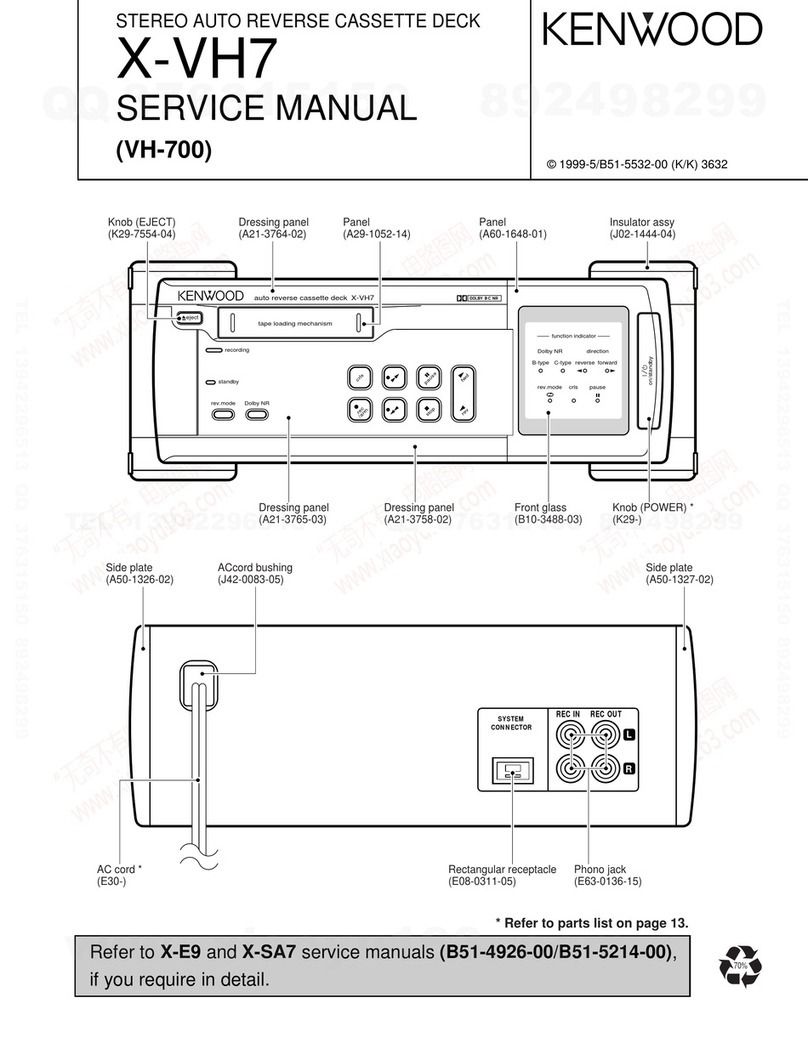
Popular Cassette Player manuals by other brands

TANDBERG TCD 3034 operating instructions

TANDBERG

TANDBERG TCD 3034 operating instructions

Philips AQ6340/00 Specification sheet

Philips

Philips AQ6340/00 Specification sheet

Hyundai H-1407 instruction manual

Hyundai

Hyundai H-1407 instruction manual

Aiwa HS-PX607 Service manual

Aiwa

Aiwa HS-PX607 Service manual

Technics RS-DC10 Service manual

Technics

Technics RS-DC10 Service manual

Philips AQ 6681/14 Instructions for use

Philips

Philips AQ 6681/14 Instructions for use

Philips AW 7250/00S Instructions for use

Philips

Philips AW 7250/00S Instructions for use

Onkyo TA-R240 Service manual

Onkyo

Onkyo TA-R240 Service manual

Pioneer CT-W851R operating instructions

Pioneer

Pioneer CT-W851R operating instructions

Technics RS-D200 operating instructions

Technics

Technics RS-D200 operating instructions

Tascam 202mkIII owner's manual

Tascam

Tascam 202mkIII owner's manual

Sony CFS-616S operating instructions

Sony

Sony CFS-616S operating instructions

Scott 675DM Servce and troubleshooting guide

Scott

Scott 675DM Servce and troubleshooting guide

Sony CFS-717S Service manual

Sony

Sony CFS-717S Service manual

Aiwa HS-TX596 YH Service manual

Aiwa

Aiwa HS-TX596 YH Service manual

Sony TCS-580V operating instructions

Sony

Sony TCS-580V operating instructions

Aiwa HS-JS385 operating instructions

Aiwa

Aiwa HS-JS385 operating instructions

Sony TC-KA2ES Service manual

Sony

Sony TC-KA2ES Service manual

manuals.online logo
manuals.online logoBrands
  • About & Mission
  • Contact us
  • Privacy Policy
  • Terms and Conditions

Copyright 2025 Manuals.Online. All Rights Reserved.