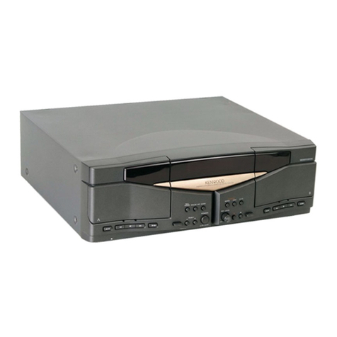
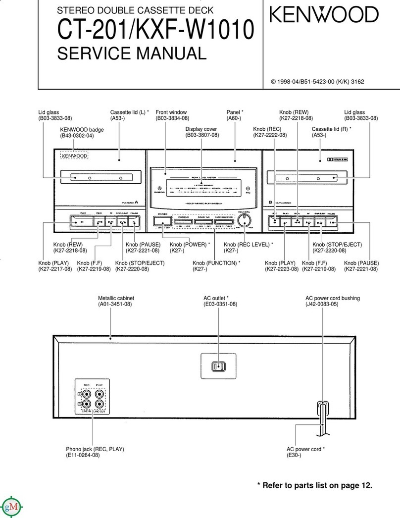
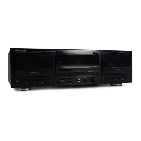
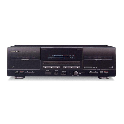
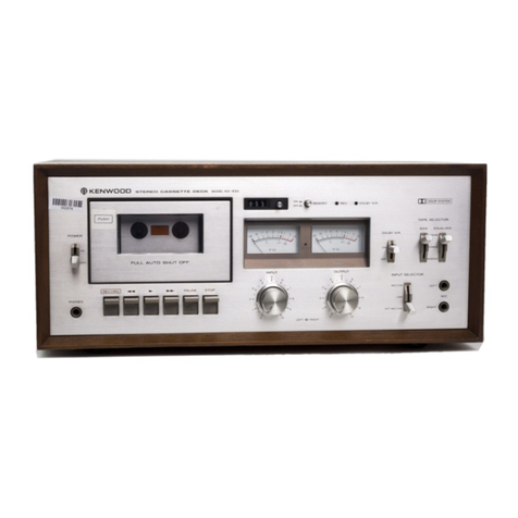
CT-401/403/KXF-W1030/W3030
13
PARTS LIST
Ref. No Add-
ress
New
Parts
Parts No. Description Desti-
nation Re-
marks
-✽B60-4555-08 INST MANUAL (CZ) 9080025990 E2
-✽B60-4631-08 INST MANUAL (ARAB) 9080026430 M
623 2B D39-0325-08 GEAR DAMPER 2000001265
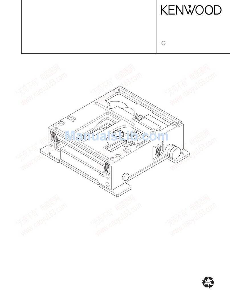
624 1B ✽D40-1693-08 MWCHANISM CWL44RR13 4380605300 3
624 1B ✽D40-1694-08 MECHANISM CWL44FF14 4380605290 1
628 1A E03-0115-05 AC PLUG ADAPTOR M
629 1A E30-0505-05 AUDIO CORD
630 1A E30-2816-05 CORD WITH PLUG
631 1C ✽E30-2952-08 AC CORD UL/CSA 463157W060 KP
631 1C ✽E30-2953-08 AC CORD 463221W060 EMY
631 1C ✽E30-2954-08 AC CORD 463321W060 T
631 1C ✽E30-2955-08 AC CORD 463421W060 X
632 1B,1C ✽E35-2655-08 FFC (16P) 160(1.25) 5421616104
- F09-0093-08 SOFT SHEET(600x250) 900307D410
638 2A ✽G01-4211-08 ELECT SPRING(L) 200804001B
639 2A ✽G01-4210-08 ELECT SPRING(R) 200704001B
640 2B ✽G01-4209-08 EJECT LEVER SPG 2A20A79880
641 2C ✽G16-0919-08 FOOT RUBBER 200604D430
-✽H10-7671-08 SNOW BOX(L) 900204001B T
-✽H10-7672-08 SNOW BOX(R) 900104001B T
-✽H10-7673-08 SNOW BOX(L) 900204001B E2E3
-✽H10-7673-08 SNOW BOX(L) 900204001B KPMXYE
-✽H10-7674-08 SNOW BOX(R) 900104001B E2E3
-✽H10-7674-08 SNOW BOX(R) 900104001B KPMXYE
- H25-1533-08 POLY BAG(60x60) 9906006049
-✽H50-3641-08 ITEM CARTON 900804001B E 1
-✽H50-3642-08 ITEM CARTON 900104001S X 1
-✽H50-3643-08 ITEM CARTON 900204001S M 1
-✽H50-3644-08 ITEM CARTON 900304001B KP 1
-✽H50-3645-08 ITEM CARTON 900204002B E 3
-✽H50-3646-08 ITEM CARTON 900304002B E2 3
-✽H50-3647-08 ITEM CARTON 900204002S E3 3
-✽H50-3648-08 ITEM CARTON 900304002S M 3
-✽H50-3649-08 ITEM CARTON 900104002B K 3
-✽H50-3702-08 ITEM CARTON 900904001B T 1
645 2C J02-1480-08 FOOT 101004001B
646 2B J19-6048-08 EJECT LEVER 2A16E79880
647 2B ✽J19-6102-08 EJECT HOLDER 2A06A79880
648 2C J42-0083-05 CORD BUSHING 4580000024
657 1A ✽K27-2409-08 POWER BUTTON 101104001B KEE2Y 3
657 1A ✽K27-2409-08 POWER BUTTON 101104001B KPTEY 1
657 1A ✽K27-2410-08 POWER BUTTON 100404001S ME3 3
657 1A ✽K27-2410-08 POWER BUTTON 100404001S MX 1
658 2B ✽K27-2411-08 VOLUME KNOB 101204001B KEE2Y 3
658 2B ✽K27-2411-08 VOLUME KNOB 101204001B KPTEY 1
658 2B ✽K27-2412-08 VOLUME KNOB 100704001S ME3 3
658 2B ✽K27-2412-08 VOLUME KNOB 100704001S MX 1
659 2A ✽K27-2415-08 PLAYER BUTTON(L)100604001B KPTEY 1
659 2A ✽K27-2417-08 PLAYER BUTTON(L)100504001S MX 1
659 2A ✽K27-2419-08 PLAYER BUTTON(L)100104002B KEE2Y 3
659 2A ✽K27-2421-08 PLAYER BUTTON(L)100404002S ME3 3
660 2B ✽K27-2416-08 PLAYER BUTTON(R)100704001B KPTEY 1
660 2B ✽K27-2418-08 PLAYER BUTTON(R)100604001S MX 1
✽ New Parts
Parts without Parts No. are not supplied.
Les articles non mentionnes dans le Parts No. ne sont pas fournis.
Teile ohne Parts No. werden nicht geliefert. 2
L : Scandinavia K : USA P : Canada R : Mexico C : China I : Malaysia
Y : PX(Far East,Hawaii) T : England E : Europe G : Germany V : China(Shanghai)
Y : AAFES(Europe) X : Australia Q : Russia H : Korea M : Other Areas indicates safety critical components.
Ref. No Add-
ress
New
Parts
Parts No. Description Desti-
nation Re-
marks
601 1A ✽A01-3762-08 METALLIC CABI 101304001B KEE2Y 3
601 1A ✽A01-3762-08 METALLIC CABI 101304001B KPTEY 1
601 1A ✽A01-3763-08 METALLIC CABI 100804001S ME3 3
601 1A ✽A01-3763-08 METALLIC CABI 100104001S MX 1
602 2A ✽A53-2195-08 CASS DOOR(L) 100504001B KPTEY 1
602 2A ✽A53-2197-08 CASS DOOR(L) 100204001S MX 1
602 2A ✽A53-2199-08 CASS DOOR(L) 101804002B KEE2Y 3
602 2A ✽A53-2201-08 CASS DOOR(L) 100204002S ME3 3
603 2A ✽A53-2196-08 CASS DOOR(R) 100404001B KPTEY 1
603 2A ✽A53-2198-08 CASS DOOR(R) 100304001S MX 1
603 2A ✽A53-2200-08 CASS DOOR(R) 101904002B KEE2Y 3
603 2A ✽A53-2202-08 CASS DOOR(R) 100304002S ME3 3
604 2A ✽A53-2207-08 CASS HOLDER(L) 200204001B KEE2Y 3
604 2A ✽A53-2207-08 CASS HOLDER(L) 200204001B KPTEY 1
604 2A ✽A53-2209-08 CASS HOLDER(L) 200204001S ME3 3
604 2A ✽A53-2209-08 CASS HOLDER(L) 200204001S MX 1
605 2A ✽A53-2208-08 CASS HOLDER(R) 200104001B KEE2Y 3
605 2A ✽A53-2208-08 CASS HOLDER(R) 200104001B KPTEY 1
605 2A ✽A53-2210-08 CASS HOLDER(R) 200104001S ME3 3
605 2A ✽A53-2210-08 CASS HOLDER(R) 200104001S MX 1
606 2A ✽A60-1859-08 FRONT PANEL 100104001B KP 1
606 2A ✽A60-1860-08 FRONT PANEL 101704001B TEY 1
606 2A ✽A60-1861-08 FRONT PANEL 100104001S MX 1
606 2A ✽A60-1864-08 FRONT PANEL 102104002B EE2Y 3
606 2A ✽A60-1865-08 FRONT PANEL 100704002S E3M 3
606 2A ✽A60-1872-08 FRONT PANEL 101704002B K 3
611 2B ✽B03-3867-08 DRESSING COVER 200604001B KEE2Y 3
611 2B ✽B03-3867-08 DRESSING COVER 200604001B KPTEY 1
611 2B ✽B03-3868-08 DRESSING COVER ME3 3
611 2B ✽B03-3868-08 DRESSING COVER MX 1
612 2A ✽B03-3862-08 CASS WINDOW(L) 100304001B
613 2A ✽B03-3863-08 CASS WINDOW(R) 1002040018
614 2B ✽B03-3865-08 LED WINDOW 100804001B
615 2B ✽B03-3866-08 LED PLATE 200304001B
616 1B ✽B19-1619-08 PLAY LENS(L) 100304002B
617 1B,2B ✽B19-1620-08 PLAY LENS(R) 100504002B
618 1B,2B ✽B19-1621-08 REC LENS 101404001B
- B46-0092-33 WARRANTY CARD K
- B46-0094-03 WARRANTY CARD Y
- B46-0095-03 WARRANTY CARD Y
- B46-0096-53 WARRANTY CARD X
- B46-0121-33 WARRANTY CARD P
-✽B60-4546-08 INST MANUAL (EN) 9080025900 E2
-✽B60-4546-08 INST MANUAL (EN) 9080025900 KPMXYT
-✽B60-4547-08 INST MANUAL (FR) 9080025910 EE3P
-✽B60-4548-08 INST MANUAL (GE) 9080025920 EE3
-✽B60-4549-08 INST MANUAL (NE) 9080025930 EE3
-✽B60-4550-08 INST MANUAL (IT) 9080025940 EE3
-✽B60-4551-08 INST MANUAL (ES) EE3M
-✽B60-4552-08 INST MANUAL (TC) 9080025960 M
-✽B60-4553-08 INST MANUAL (PL) 9080025970 E2
-✽B60-4554-08 INST MANUAL (HU) 9080025980 E2
✽ New Parts
Parts without Parts No. are not supplied.
Les articles non mentionnes dans le Parts No. ne sont pas fournis.
Teile ohne Parts No. werden nicht geliefert. 1
L:Scandinavia K : USA P : Canada R : Mexico C : China I : Malaysia
Y : PX(Far East,Hawaii) T : England E : Europe G : Germany V : China(Shanghai)
Y : AAFES(Europe) X : Australia Q : Russia H : Korea M : Other Areas indicates safety critical components .
CT-401/403/KXF-W1030/W1030-S/W3030/W3030E/W3030-S
