DV-403
5
DISASSEMBLY FOR REPAIR
Extension cable(C) Extension
cable(B)
Extension
cable(B)
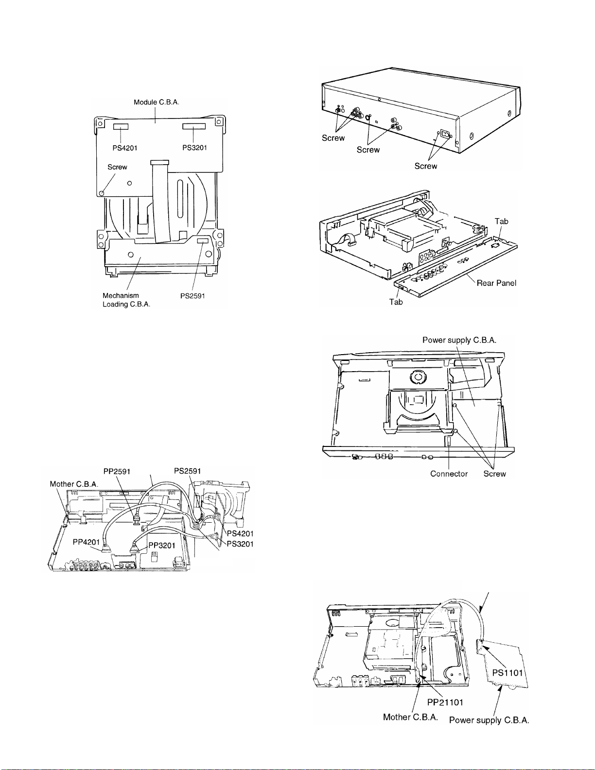
1-9 Checking the Mother C.B.A.
1. Remove the 4 screws.
2. Release the 2 tabs.
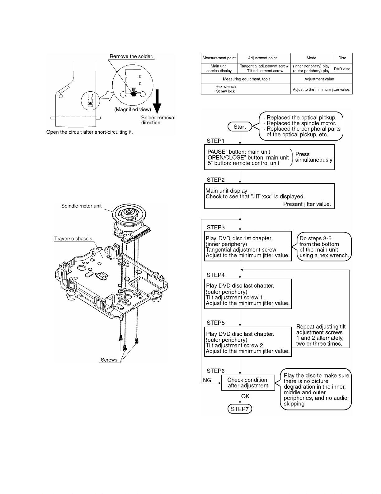
2. Assembling and Disassembling the Optical
Pickup (Mechanical Parts)
The optical pickup can be damaged by static electricity from
your body. Be sure to take static electricity countermeasures
when working around the optical pickup.
2-1 Handling the Optical Pickup
The optical pickup can be damaged by static electricity
from your body. Be sure to take static electricity counter-
measures when working around the optical pickup.
1. The optical pickup is an extremely high-precision mecha-
nism. Do not subject it to strong impact.
2. To preserve the quality of the optical pickup replacement
parts during transport and installation, the terminals of
the laser diode are short-circuited. After replacing the
parts, use the proper procedure to return the laser diode
to its original condition. (Refer to page8/2-11 Assembling
the Optical Pickup.)
3. Testers cannot be used to check the laser diode of the
optical pickup. The power supply inside the tester can
easily damage the laser diode.
4. Take care when handling the flexible cable because
excessive force can cause it to break.
5. You cannot adjust the semifixed resistor for laser power
adjustment. Do not turn it.
2-2 Disassembly Procedure
Use the following procedure to replace major parts.
For the assembly procedure, follow the flow chart in reverse.
3. Checked by connecting the module C.B.A. and the moth-
er C.B.A. with the extension cables.
Extension cable (B)x2
Module C.B.A. Mother C.B.A.
PS3201-PP3201
PS4201-PP4201
4. Checked by connecting the mechanism loading C.B.A.
and the mother C.B.A. with the extension cables.
Extension cable(C)
Mechanism Loading C.B.A. Mother C.B.A.
PS2591-PP4201
Note
Be sure to initialize the player whenever you replace a
C.B.A. (Refer to page17/4-1, Initializing the DVD player.)