Keyscan NETCOM6P User manual

NETCOM6P/CIM RN (Encrypted) Installation
Guide
Enclosed with the NETCOM6P are two sets of instructions for reverse network (RN)
communication:
For mounting a NETCOM6P on a CIM circuit board with reverse network
communication, follow the instructions contained in this installation guide
For mounting a NETCOM6P directly on a control board with reverse network
communication follow the NETCOM6P/ACU RN (Encrypted) Installation Guide also
enclosed with the NETCOM6P
If you require NETCOM6P instructions for a non-reverse network application, refer to the
Keyscan Product Documentation Library CD—NETCOM6P Installation Guide.
The NETCOM6P is only compatible with CIM modules or plugged directly into a PC109x or
higher control board’s M1 socket for reverse network communication.
Before commencing to install the NETCOM6P, be sure to review the K-RN/V-RN Reverse
Network Overview section.
K-RN/V-RN Reverse Network Overview
Keyscan’s RN licenses—AUR-RN for Aurora, K-RN for System VII and V-RN for Vantage—
are designed so that a programmed access control unit at a remote location initiates
communication via an encrypted NETCOM6P over a private or public network to the
PC/server at a host location.
Installation Coordination –Host & Remote Locations
The RN license involves installing and configuring reverse network encrypted
communication software at a host location and installing hardware components at a remote
location. You must coordinate certain settings between the two locations in order that the
ACU/NETCOM6P at the remote location can establish network communication back to the
PC/server with the encrypted communication software at the host location.
the technician installing the hardware components must have a host-location IP
address that the ACU connects to on the network
both the host and remote locations must have the same encryption key
the host location requires the serial # of the designated reverse network control
board
a valid path and connectivity must exist from the PC/server with the encrypted
reverse network communication manager at the host location to the
NETCOM6P/reverse network control board at the remote location—may require a
network administrator
The hardware technician must program the access
control board with a host-location IP address along
with other settings. The IP address the technician
programs into the control board depends on the
network configuration. We have provided two general
network configuration outlines: an
Internet/Intranet/WAN configured network that is
exposed publicly and a LAN that is closed. Refer to
the network configuration that best approximates
your network application.

Keyscan Inc. A Member of the Kaba Group
2
Network Configuration - Internet/Intranet/WAN
- Host Router or End Point with External IP Address example.
Settings
Host Location
Remote Location
IP Address
Port #
Gateway
Encryption Key
Router with port
forward or router table
to PC/server with
Keyscan reverse
network encrypted
communication
manager
Same encryption
key/bit setting as
remote location
ACU
programmed with host
router or end point
external IP address
override port—optional
NETCOM6P
programmed with static
IP address or if using
DHCP server dynamic IP
Gateway (if static IP
above)
Port # of host router/end
point
Same encryption key/bit
setting as host location
Figure 1 - Example of Internet/Intranet/WAN with external IP Address
Host Location
Remote Access Control Location
Internet/Intranet/WAN
Encrypted NETCOM6P
Internal Static IP: 172.16.0.2
Gateway: 172.16.0.1
Port: 3001
Encryption Key: 12345678
12345678 12345678 12345678
PC/Server with RN Encrypted Communication Manager
- Communication manager runs as a service
- Internal IP 192.168.0.2
- Encryption key: 12345678 12345678 12345678 12345678
Note on Routers & Switches
Ensure that routers and switches
are configured for inbound and/or
outbound communication between
the PC at the host location and the
NETCOM6/control board at the
remote location.
Remote Router
Internal IP: 172.16.0.1
External IP: 23.58.59.64
Host Router/End Point*
Internal IP: 192.168.0.1
External IP: 24.48.52.134
Port Forward - 3001
*End Point
This may be a firewall,
DSL/cable modem or
other device with the
external IP that is
exposed to the public
side of the network at
the host location.
IP Addresses
The IP addresses in this illustration
are merely shown as examples.
Control
Board
PC109x
CIM 0
with NETCOM6P
Reverse network
applications require
CANBUS 1 & 2
KI-00455E-08-12
Control Board
(PC109x)
Control Board
Reverse Network
Programming:
- Host Router/EndPoint
External IP: 24.48.52.134
- Port: 3001
(May also include an
alternate host router
external IP address if
available)

NETCOM6P/CIM - RN Installation Guide
3
Network Configuration –LAN
- Closed network with no public exposure example
Settings
Host Location
Remote Location
IP Address
Port #
Encryption Key
PC/server with Keyscan
reverse network
encrypted
communication
manager
Same encryption
key/bit setting as
remote location
ACU
programmed with IP
address of host
PC/server with Keyscan
reverse network
encrypted
communication manager
NETCOM6P
programmed with static
IP address or if using
DHCP server dynamic IP
Port # of host PC/server
Same encryption key/bit
setting as host location
Figure 2 - Example of LAN closed with no public exposure
Host
Location
Remote Access
Control Location
LAN
Encrypted NETCOM6P
Internal Static IP: 192.168.0.4
Encryption Key: 12345678
12345678 12345678 12345678
Port: 3001
Control Board
Reverse Network Programming:
- PC/Server internal IP:
192.168.0.2
PC/Server with RN Encrypted Communication Manager
- Communication manager runs as a service
- Internal IP 192.168.0.2
- Port 3001
- Encryption key: 12345678 12345678 12345678 12345678
IP Addresses
The IP addresses in this illustration
are merely shown as examples.
CIM 0
with NETCOM6P
Control Board
(PC109x)
Reverse network
applications
require CANBUS
1 & 2
KI-00456E-08-12

Keyscan Inc. A Member of the Kaba Group
4
Installation Procedures for Reverse Network
For installing a NETCOM6P on a CIM circuit board for reverse network communication
follow all the instructions outlined in this guide.
Before You Start
Verify that you have all the parts as outlined below
Ensure that you have coordinated settings, including the encryption key, with the host
location as outlined on pages 1 to 3
Have a control board with firmware 7.95/8.75 on the control board programmed with
the host-location IP address for System VII or Vantage)
Have firmware 9.21/9.02 on all control boards for Aurora
Obtain a static IP address, Subnet Mask, and, if applicable, a Gateway (for a
configuration similar to Figure 1) from the network administrator for each NETCOM6P
unless using a DHCP server. Space is provided to record the address settings at the
back
Ensure you install the latest Keyscan NETCOM Program Tool utility on the enclosed CD
on a laptop or PC that can be serially connected to program the NETCOM6P
Have a copy of the CIM Installation Guide
Important
The NETCOM6P involves 2 procedures, temporary serial programming connections and
permanent operation connections. Refer to the appropriate connection diagrams.
Ensure that you follow all the instructions beginning on page 5. Ensure that you program
the NETCOM6P and program the control board as instructed.
As networks can be highly complex structures with a labyrinth of routers, firewalls, and
switches, as well as layers of security protocols, you may be required to engage the
services of a network administrator to establish communication between the two locations.
Please be aware that in addition to this document which pertains to the required setup at
the remote location, a sister document –K-RN Setup or V-RN Setup –is included with the
RN license and encrypted communication software at the host location.
Contents
Parts List
Set Control Board for RN
NETCOM6P
1
Install NETCOM Program Utility
6
Serial Data Cable
1
Program NETCOM6P
6
Encrypted Communication CD
1
Serial Program Connections
11
Program the RN Control Board
15
Operational Connections
19
Specifications
24

NETCOM6P/CIM - RN Installation Guide
5
Set Control Board for Reverse Network
In this set of procedures you will configure the control board for reverse network
communication at one of the following bit rates: 9600 or 57,600.
See the table below for reverse network jumper settings.
Set Reverse Network –Jumper J16 or S2 DIP Switches on Control Board
The table below outlines reverse network configurations for PC109x control boards.
Depending on the PC109x control board version, which either have jumpers at J16 or DIP
switches at S2, refer to the relevant settings.
System Jumper J16 –Reverse Network Settings
Communication
Bits/Second
Mode
Jumper #
Settings
0=Off/1=On
9,600
Reverse network
1 & 2 & 6
1 1 1
57,600
Reverse network
1 & 2 & 6
1 0 1
S2 DIP Switches
Communication
Bits/Second
Mode
Switch #
Settings
0=Off/1=On
9600
Reverse network
1 & 2 & 3
1 0 0
57,600
Reverse network
1 & 2 & 3
1 0 1
The recommended setting is 57,600.
Steps to Set the Control Board for Reverse Network and Set the Bit Rate
1. Configure the control board for reverse network setting either the jumpers at J16 or
the DIP switches at S2 as outlined above.
2. Note the bit rate you have selected for the control board. You require this setting
when programming the NETCOM6P.
3. Go to Install NETCOM Program Tool Utility on the next page and follow each set of
setup instructions.
Figure 3 - Location of J16 Jumpers
J16
J16
123456 78
ABCDEFGH
COMMUNICATION STATUS
TD1 RD1 TD2 RD2 TD3 RD3 TD4 RD4
READER 1READER 2READER 3READER 4READER 5
CONTROL 2
CONTROL 4
CONTROL 3
CONTROL 5
J1J6 J17
Protective ACU
Cover
Cut View of CA8500B
Location of J16 is the
same on all CA & EC
control boards.
System Configuration
Jumpers J16
KI-00143E-07-11

Keyscan Inc. A Member of the Kaba Group
6
Figure 4 - Location of S2 DIP Switches
COMMUNICATION STATUS
TD1 RD1 TD2 RD2 TD3 RD3 TD4 RD4
READER 1READER 2READER 3READER 4READER 5
CONTROL 2
CONTROL 5
CONTROL 3
Protective ACU Cover
Cut View of CA8500B
Location of S2 is the
same on all CA & EC
control boards.
KI-00143E-04-13
S1
S2
S3
O
N1 2 3 4 5 6 7 8 9 10 11 12
Install Keyscan NETCOM Program Tool Utility
Each NETCOM6P that you are installing must be programmed with the NETCOM Program
Tool Utility software. Ensure you have the latest NETCOM Program Tool Utility software
installed, which is on the enclosed CD; otherwise you may encounter communication
difficulties. You will require a PC or laptop that has a direct serial connection to the
NETCOM6P via the CIM board’s COM2 terminal to program the device. To install the
NETCOM Program Tool Utility software, load the Encrypted Communication CD into the CD-
ROM or DVD drive. Observe the firewall and anti-spyware message and close the screen.
Select Install NETCOM Program Tool from the Encryption Installation screen.
About the Encryption Key
The encryption key for the NETCOM6P must consist of one of the following bit settings: 32
characters (128 bit), 48 characters (192 bit) or 64 characters (256 bit). Characters can be
as follows in any combination:
alpha A—F
numeric 0—9
example of 128 bit key —A91376F1 C3621FBC DD68917E 1006B167
The encryption key can be created at either the host location or the remote access control
location. But it must be entered exactly the same in the following two Keyscan software
utilities:
Application Utilities screen –Aurora (host location)
System Settings—Reverse Network utility (host location)
NETCOM Program Tool utility (remote access control location)
When requested in the Steps to Program the NETCOM6P with Encryption procedures,
ensure that you enter the same encryption key that is used at the host location.
Program the NETCOM6P
The NETCOM6P involves making a temporary connection to program the device and then
making a permanent connection to operate the device as outlined:
See Figure 5 to Figure 8 for temporary serial programming connections to the
laptop/PC with the NETCOM Program Tool utility.
See Figure 9 and Figure 10 for permanent operating connections on the network.

NETCOM6P/CIM - RN Installation Guide
7
About the Reset Function
During the NETCOM6P programming procedures, you are prompted to reset the device,
which is a soft re-boot. This is equivalent to a power cycle.
Steps to Install and Program the NETCOM6P
The NETCOM6P plugs directly into the CIM that is to be designated as CIM 0.
For programming the NETCOM6P (required), use a direct serial connection via the COM2
terminal block on CIM 0 as instructed. Also ensure you place jumpers ON J12 during the
programming procedure when instructed.
As an option, the NETCOMP can be programmed off-site before installation providing you
have a 12 VDC power supply that can be connected to the CIM’s TB4 power terminal. See
Figure 6 or Figure 8.
Steps to Install and Program the NETCOM6P…cont’d
1. Mount the NETCOM6P into SCKT1 on CIM 0 in the correct orientation as shown below.
Do not change the orientation of the standoffs.
TD1
RD1
TD2
RD2
GND
RTS
CTS
GND
RTS
CTS B3 B2 B1 B0 Diag
J2
RESET
-
CAN2
+
EGND
-
CAN1
+
GND
V +
(+12V)
SCKT1
PC106x
J1
J7
J8
J6
J5
CAN2
CAN1
1 2 1 2 1 2 1 2
Rx - COM COM
CAN CAN - Tx
J3J4 J9
J12
Power
Good
COM1
COM2
HDR1
J10
J11
Fault
(Flashing)
RJ45
Terminal
Jack
RESET
NETCOMP
Standoffs
NETCOMP
CIM
Standoff
- correct
mounting
orientation
Standoff
Program Mode
Jumper ON J12
KI-00466E-04-13
2. Mount the CIM/NETCOM6P in its designated location in the metal enclosure.
3. On the CIM circuit board, place a jumper on J12.
4. Connect the ribbon cable from the HDR1 terminal on the CIM circuit board to the H2
terminal on the control board. The H2 terminal provides power for programming the
NETCOM6P.
5. Ensure the control board has power.
6. If the control board is newly installed and this is the first time it is powered up,
restore the factory defaults as outlined depending on the version of PC109x control
board:
J16 Jumpers - place a jumper ON J16—pin H, then momentarily place a jumper
ON J1—Clear Memory to load the factory defaults. Allow approximately 2
minutes and do not make any changes while the control board re-configures.
Remove the jumper from J16—pin H
S1 and S3 Switches –After applying power, press S1, wait 5 seconds, and then
press S3 within 10 seconds to load the factory defaults. Allow approximately 2
minutes and do not make any changes while the control board re-configures.
7. Connect the RS-232 serial cable from the laptop or PC to the COM2 terminal block on
the CIM circuit board. See Figure 5 or Figure 7.
8. Turn on the laptop or PC connected to the CIM circuit board.
9. Select start > All Programs and select Keyscan NETCOM Program Tool from the
Keyscan menu.

Keyscan Inc. A Member of the Kaba Group
8
Steps to Install and Program the NETCOM6P…cont’d
10. From the Keyscan NETCOM Utility screen, click Program NETCOM Device.
11. From the Select NETCOM Device Type screen, click on the Program NETCOM6 Family
of Boards button.
12. From the Program NETCOM6B, NETCOM6 & NETCOM6P Boards screen, enter the IP
address assigned to the NETCOM6P. If using DHCP, enter 0.0.0.0 in the IP Address to
Assign.
13. If a Subnet Mask is required, select it from the drop down list.
14. If the NETCOM6P requires a gateway to communicate on the network, enter the
gateway address in the default Gateway text box.
15. From the Program via IP Address or Serial Port, select the port on the PC/laptop with
the serial connection to the NETCOM6P via the CIMs COM2 terminal.
16. Select the baud rate that corresponds to the control board’s J16 or S2 communication
bit rate settings—9,600 or 57,600 for reverse network.
17. Leave Ethernet Connection Type set on Automatic Negotiation unless the IT
administrator gives a specific setting.
If the NETCOM device experiences network communication difficulties, you may
have to alter the Ethernet Connection Type from automatic negotiation. (The
Ethernet Connection Type is the network speed & duplex setting). Set the
NETCOM so it matches the network equipment setting. If the network equipment

NETCOM6P/CIM - RN Installation Guide
9
was on an automatic setting, then reconfigure both the network equipment,
which may include routers or switches, and the NETCOM to a matching fixed
speed and duplex setting. As an example, NETCOM = 100 Mbit/Half Duplex –
Network equipment = 100Mbit/Half Duplex.
18. The Discovery Port 77FE is disabled by default. Keyscan recommends that you leave it
on the default setting. This function is principally for troubleshooting communication
difficulties.
19. Click on a radio button that corresponds to the encryption bit setting of the host
location.
20. Enter the same encryption key that was entered in the Keyscan Reverse Network
Settings Encryption utility at the host location.
21. Select the Reverse Network button.
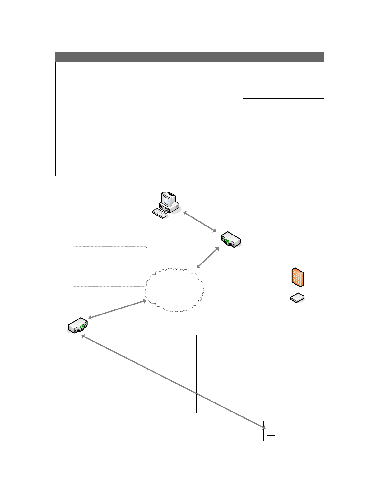
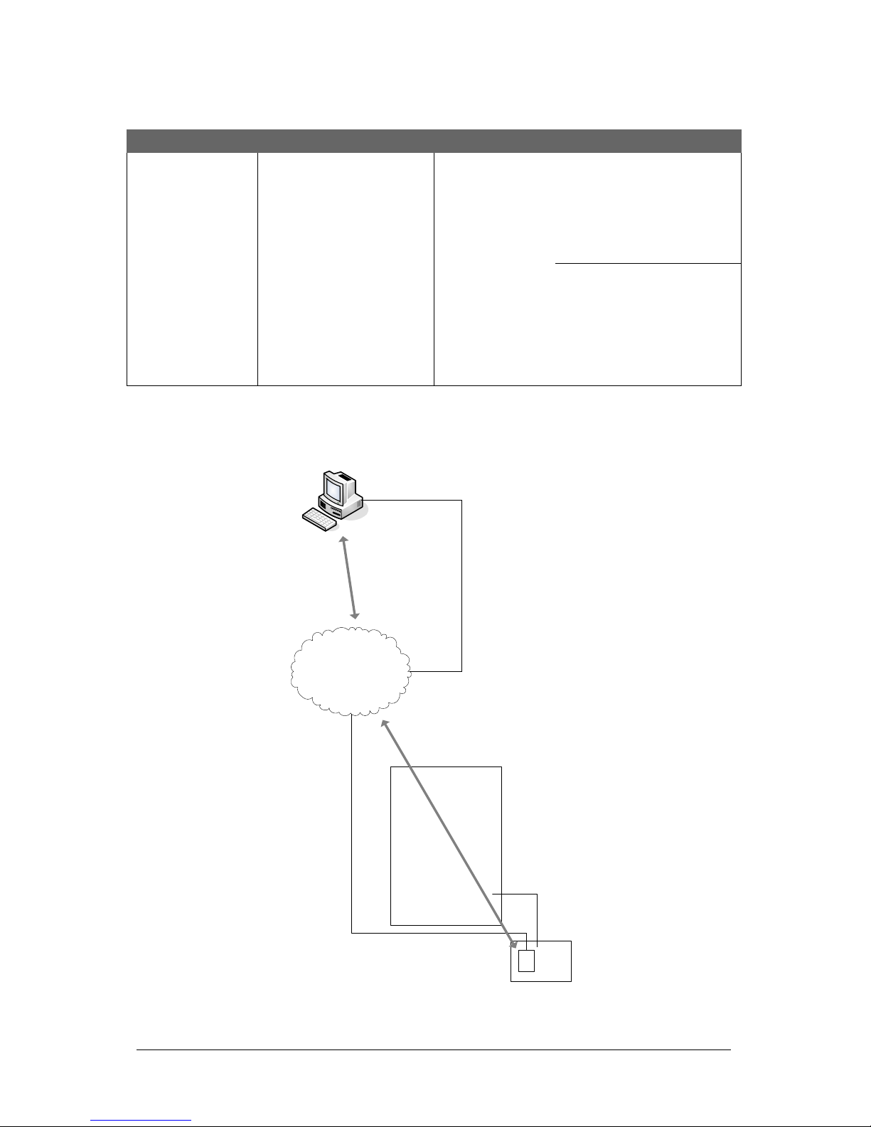
22. In the Reverse Network Port Number text box and depending on the network
configuration, enter the port number of the router, end point or the PC/server with
the Reverse Network Communication Manager at the host location. Generally this is
port 3001.
23. Select the radio button –Static Local Port or Dynamic Local Port (50,000 –59,999)
depending on whether the inbound port of the router/endpoint is assigned a static
port or a range of dynamic ports at the remote location.
If Static Local Port applies ensure that the router/end point is configured for
inbound communication using the same port number as entered in the Reverse
Network Port Number field.
24. Click on Save.
25. Click on the Program NETCOM button.
26. From the Reverse Network Settings confirmation box—Do you wish to continue…, click
on the Yes button.
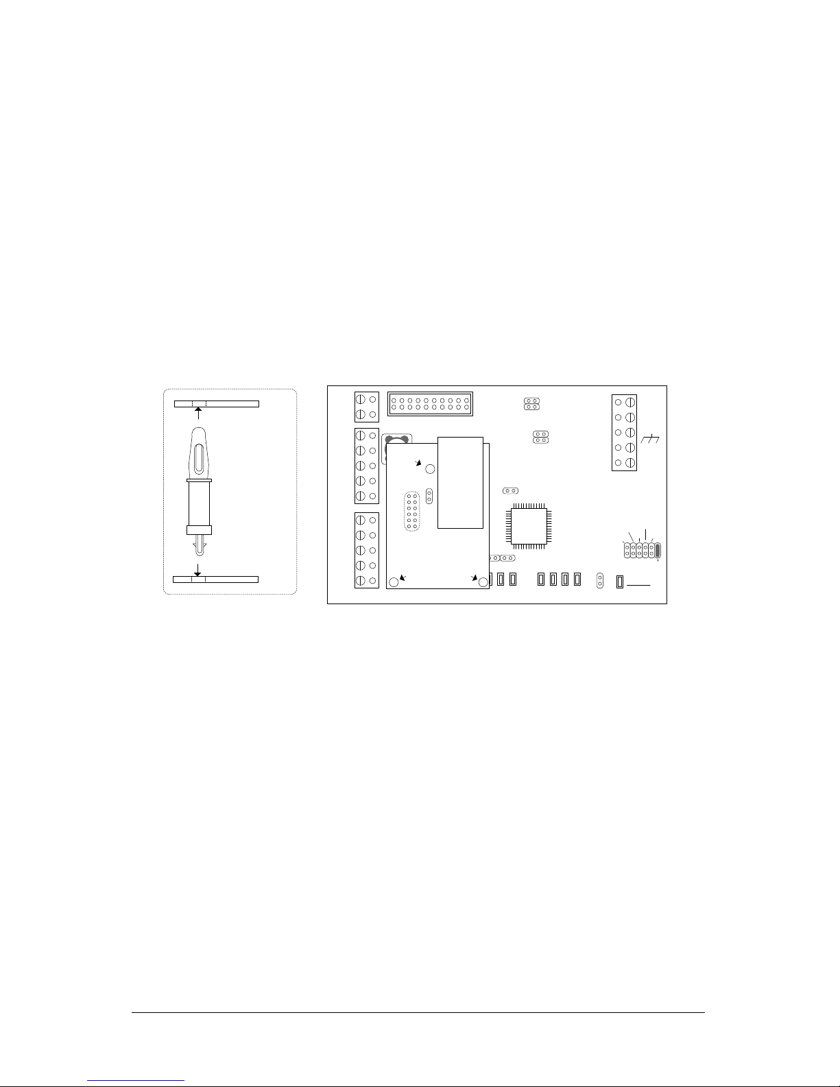
27. The NETCOM Program Settings screen indicates it is waiting for a NETCOM reset or
power cycle. Momentarily place a jumper on the CIM board’s J1 RESET pins, then
remove the jumper, and wait while the NETCOM is programmed.
If the NETCOM does not program on the 1st attempt, keep the NETCOM Program
Settings screen open and press the F4 key. Click inside the box to the left of
Program Server Address Settings Only so it has a check mark. Ensure the
settings have been retained, including the IP Address, otherwise re-enter them.
Click on the Program NETCOM button. If successful, program the NETCOM one
more time. For additional programming tips, press the F1 key with the Keyscan
NETCOM Program Settings screen open.
28. When prompted by the NETCOM Program Tool utility, ensure that you remove the
temporary RS-232 serial cable from the CIM circuit board’s COM2 terminal after the
device has been programmed. Leave the data cable connected to the PC/laptop.
29. Momentarily short the RESET jumper on the NETCOM6P.
30. Leave the NETCOM Program Tool Utility open.
31. Remove the jumper from J12 on the CIM circuit board.

Keyscan Inc. A Member of the Kaba Group
10
Steps to Install and Program the NETCOM6P…cont’d
32. Place a jumper ON J4 on the CIM unit to enable the board for network
communication. This designates it as CIM 0.
33. Momentarily place a jumper on the CIM board’s J1 RESET pins to initiate the jumper
change in the preceding step.
34. At the PC/laptop, click on the OK button in the Disconnect the serial cable… screen.
35. Go to the next set of instructions—Set the IP Address on Control Board on page 14.

NETCOM6P/CIM - RN Installation Guide
11
Serial Programming Connections
Establish a serial programming connection from the PC or laptop using the enclosed data
cables.
If the PC or laptop does not have a serial port, use Keyscan's optional USB-SER Adaptor.
Figure 5 - Serial Programming Connections Powered via H2 on the Control Board
PC or laptop with Keyscan
NETCOM Program Tool Utility.
Serial Data Cable
with loose
conductors
Green
Red
Black
Current Draw : CIM 150 mA +
NETCOMP 140 mA = 290 mA
CIM 0
TD1
RD1
TD2
RD2
GND
RTS1
CTS1
GND
RTS2
CTS2 B3 B2 B1 B0 Diag
J2
RESET
-
CAN2
+
EGND
-
CAN1
+
GND
V +
(+12V)
SCKT1
Tx Data
PC106x
J1
J7
J8
J6
J5
CAN2
CAN1
Rx Data
1212 1212
COM COM
CAN CAN
J3J4 J9
J12
Power
Good
Fault
COM2
HDR1
J10
J11
RJ45
Terminal
Jack
J1
U2
NETCOMP
Standoffs
To program
NETCOM2P/6P
jumper ON J12
KI-00465E-07-12
COM1
Control Board
(PC 109x)
Common AUX Inputs - E24
2322
2120191817
H1H2
Connect ribbon cable from
HDR1 on CIM 0 to H2 on
control board. Control board
requires power from DPS-15.
Place a jumper on J12 to set
the CIM for Program mode.
After programming remove
the jumper from J12 to set the
CIM on Run mode. Ensure
CIM 0 has a jumper on J4.

Keyscan Inc. A Member of the Kaba Group
12
Figure 6 - Serial Programming Connections via Independent 12 VDC Supply
PC or laptop with Keyscan
NETCOM Program Tool Utility.
Serial Data Cable
with loose
conductors
Green
Red
Black
+
-
to
12VDC
power
supply Current Draw : CIM 150 mA + NETCOMP 140 mA = 290 mA
CIM 0
TD1
RD1
TD2
RD2
GND
RTS1
CTS1
GND
RTS2
CTS2 B3 B2 B1 B0 Diag
J2
RESET
-
CAN2
+
EGND
-
CAN1
+
GND
V +
(+12V)
SCKT1
Tx Data
PC106x
J1
J7
J8
J6
J5
CAN2
CAN1
Rx Data
1212 1212
COM COM
CAN CAN
J3J4 J9
J12
Power
Good
Fault
COM2
HDR1
J10
J11
RJ45
Terminal
Jack
J1
U2
NETCOMP
Standoffs
To program
NETCOM2P
jumper ON J12
KI-00257E-07-12
COM1

NETCOM6P/CIM - RN Installation Guide
13
Figure 7 - Optional USB-SER Serial Programming Connections Powered via H2 on
Control Board
PC or laptop with Keyscan
NETCOM Program Tool Utility.
Use 3 loose
RS-232 wires.
Green
Red
Black
Current Draw : CIM 150 mA +
NETCOMP 140 mA = 290 mA
CIM 0
TD1
RD1
TD2
RD2
GND
RTS1
CTS1
GND
RTS2
CTS2 B3 B2 B1 B0 Diag
J2
RESET
-
CAN2
+
EGND
-
CAN1
+
GND
V +
(+12V)
SCKT1
Tx Data
PC106x
J1
J7
J8
J6
J5
CAN2
CAN1
Rx Data
1212 1212
COM COM
CAN CAN
J3J4 J9
J12
Power
Good
Fault
COM2
HDR1
J10
J11
RJ45
Terminal
Jack
RESET
NETCOMP
Standoffs
To program
NETCOM2P/6P
jumper ON J12
KI-00467E-04-13
COM1
BRN
WHT
GRN
WHT
+ TX - + RX -
485 OUT 485 IN
Connect ribbon cable from
HDR1 on CIM 0 to H2 on
control board. Control board
requires power from DPS-15.
Place a jumper on J12 to set
the CIM for Program mode.
After programming remove
the jumper from J12 to set the
CIM on Run mode. Ensure
CIM 0 has a jumper on J4.
Control Board
(PC 109x)
Common AUX Inputs - E24
2322
2120191817
H1H2

Keyscan Inc. A Member of the Kaba Group
14
Figure 8 - Optional USB-SER Serial Programming Connections via Independent 12
VDC Supply
PC or laptop with Keyscan
NETCOM Program Tool Utility
Green
Red
Black
Use 3 loose
RS-232 wires
BRN
WHT
GRN
WHT
+ TX - + RX -
485 OUT 485 IN
USB cable
+
-
to
12VDC
power
supply Current Draw - CIM 150mA + NETCOMP 140mA = 290mA
CIM 0
TD1
RD1
TD2
RD2
GND
RTS1
CTS1
GND
RTS2
CTS2 B3 B2 B1 B0 Diag
J2
RESET
-
CAN2
+
EGND
-
CAN1
+
GND
V +
(+12V)
SCKT1
Tx Data
PC106x
J1
J7
J8
J6
J5
CAN2
CAN1
Rx Data
1212 1212
COM COM
CAN CAN
J3J4 J9
J12
Power
Good
Fault
COM2
HDR1
J10
J11
RJ45
Terminal
Jack
RESET
NETCOMP
Standoffs
To program
NETCOM2P/6P
jumper ON J12
KI-00258E-04-13

NETCOM6P/CIM - RN Installation Guide
15
Program the RN Control Board
In this set of procedures you will input the IP address of the router, endpoint or PC/server
with the Keyscan Reverse Network Communication Manager at the host location depending
on the network configuration. This allows the control board to initiate communication back
to the host location. This must be the same control board that was jumpered for reverse
network communication on page 5. Ensure the board has firmware version 7.95/8.75.
Steps to Program the Control Board with a Host-Location IP Address
1. Ensure that the access control board has power.
1. Do one of the following steps depending on the PC109x version of control board:
J16 Jumpers - Remove the jumpers from J16—pins F & G. And then place a
jumper on J6 momentarily to reset the control board and then remove the
jumper.
S2 DIP Switches –Turn S2 –switches 7 and 8 OFF. And then press and release
the S1 switch.
2. Connect the 3 loose wires from the serial programming cable to the communication
terminal block—TB4—as shown below.
You can also remove the terminal block from TB4 in the lower right corner of the
access control board, make the connections and then re-mount the terminal
block.
to Com Port on PC or laptop
Isolate and tape unused wires.
`
This is a temporary
programming connection
only.
GND
RS-232 (COM4)
Control Board
(PC 109x)
Green
Black
TD
RD
DCD
DTR
CTS
Red
IOCB (COM1)
RX
TX KI-00399E-10-13
Control Board
S2 - DIP switches 7 & 8 = OFF (PC1097 or later)
or
J16 –pins F & G = OFF (PC1094 & PC1095)
3. From the PC or laptop with the NETCOM Program Tool Utility main screen open, select
the Keyscan Hyper Terminal button.
Continued on the next page….

Keyscan Inc. A Member of the Kaba Group
16
Steps to Set IP Address on Control Board ...cont’d
4. In the Open Comm Port Selection screen, select the COM port on the PC laptop
connected with the access control board.
5. Set the Baud Rate to match J16 or S2 on the access control board.
6. Select the Open Port button.
7. With the Hyper Terminal screen open, it is currently blank, momentarily remove the
jumper from pin 1 on J16 and then put it back on or turn S2.1 off then back on.
Within 15 seconds, press and hold the c (lower case or upper case) on the keyboard
until the Hyper Terminal menu opens. If the menu starts to scroll, release the “c” and
wait until the menu has stabilized before going to the next step.
8. The Hyper Terminal offers the following menu selections:
1) Set Primary IP Address
2) Set Secondary IP Address
3) Display IP Address
4) Clear IP Address
5) Set Port Number
9) Exit
9. Select 1) Set Primary IP Address.
10. Enter the IP address of the host router, end point or the PC/server running the
Keyscan Reverse Network communication manager that was provided by the host
location.
If you make a typing error, do not use the backspace key. Press the Enter key
and repeat steps 11 & 12.
Ensure the correct IP address format is used with periods separating appropriate
digits as shown in the example 192.168.100.12
11. Press the Enter key.
12. Verify the correct IP address has been programmed by selecting: 3) Display IP
Address.
13. Do one of the following:
If the IP address is correct go to the next step.
If the IP address is incorrect, repeat steps 11 to 14.
Continued on the next page…

NETCOM6P/CIM - RN Installation Guide
17
Steps to Set IP Address on Control Board ...cont’d
14. As an option, you can set a secondary IP address and/or set an override port number
as outlined below provided they have been specified by the host location; otherwise
go to step 17.
To set a secondary IP address, select 2) Set Secondary IP Address and enter a
secondary IP address. You must have entered a primary IP address, otherwise
the secondary address will not be used if a primary IP address is non-existent. If
not entering a different secondary address, Keyscan recommends entering the
primary IP address in the secondary location.
To set a port number which is an override to the Reverse Network Port Number
programmed into the NETCOM6P, select 5) Set Port Number and enter a valid
port. This override port can also be entered in the Keyscan Client software.
15. When you have completed the ACU programming, select 9) Exit.
16. Exit HyperTerminal and close the NETCOM Program Tool Utility.
17. Disconnect the serial programming cable wires from the Communication terminal
block—TB4 on the control board and from the PC/laptop.
18. Go to the next set of instructions—Configure the Control board and CIMs.

Keyscan Inc. A Member of the Kaba Group
18
Configure the Control Board & CIMs
After programming the NETCOM6P and programming the control board with the host-
location IP address, review the general steps below to configure the control board and
CIMs for operation. Also refer to the CIM Setup Guide for instructions.
1. Refer to the NETCOM6P Operational Connections—Figure 9 and Figure 10 for
permanent on-going operation.
2. Ensure that the CIM with the network connection has a jumper ON J4. This designates
it as CIM 0.
3. Ensure that you have set the baud rate for all other CIMs to the same jumper setting
as set on CIM 0—9600 or 57,600.
4. If using global anti—pass back, ensure that one CIM is set as a Global Master by
placing a jumper ON J3. All other CIMs are set as slaves. A global master is not
required if global functions are not used.
5. Ensure that the first and last CIMs have CANBUS 1 & 2 termination jumpers set.
Reverse network communication requires CANBUS 1 & 2
6. After the control board and the NETCOMP have been programmed and connected to
the network, confer with the host location and verify the Keyscan Reverse Network
Settings Encryption and the Client software for Reverse Network communication have
been programmed.
7. After you have made all the necessary wiring and ribbon cable connections, and the
host location has installed and configured the reverse network communication
software, ensure the control boards/CIMs have power.
8. When initially powered, the CIMs will boot-up and run a self-diagnostic test. Check the
CIMs for the following:
Power Good / Fault LED—solid green
9. On the control board, the initial state of the LEDs are as follows:
System Status—solid amber
TD3—flashing momentarily approx. every minute
RD3—flashing momentarily approx. every minute following TD3
10. When communication is established with the host location, the LEDs on the control
board change to the following states:
11. System Status—solid green
12. TD3—flashing green frequent
13. RD3—flashing red frequent
14. When communication has been verified, have the host location perform a panel
upload from a Client module.
15. If the CIMs Power Good /Fault LED is flashing green or the control board’s
Communication Status COM3—TD LED only flashes x4 approximately every 60
seconds on a call out cycle to make a connection with the host location, you may have
to resolve communication issues. Refer to Troubleshoot Communication Issues to
resolve potential causes for communication faults.
Also if there is no communication, the host location Client software will report a
Communication Status Failed message

NETCOM6P/CIM - RN Installation Guide
19
NETCOM6P Operational Connections
Figure 9 and Figure 10 illustrate NETCOM6P operating connections via CIM 0. Refer to the
CIM Guide for complete instructions on setting up and installing CIMs.
Figure 9 –NETCOM6P Mounted on CIM 0
10 or 100 Base T
to
network
or
router
See CIM to CIM
Connections
diagram.
Current Draw - CIM 150 mA + NETCOMP 140 mA = 290mA
KI-00259E-07-12
Connect ribbon cable from
HDR1 on CIM to H2 terminal
on control board.
Jumper ON
J4
TD1
RD1
TD2
RD2
GND
RTS
CTS
GND
RTS
CTS B3 B2 B1 B0 Diag
J2
RESET
-
CAN2
+
EGND
-
CAN1
+
GND
V +
(+12V)
SCKT1
PC106x
J1
J7
J8
J6
J5
CAN2
CAN1
1212 1212
Rx-COM COM
CAN CAN-Tx
J3J4 J9
J12
Power
Good
Fault
COM1
COM2
HDR1
J10
J11
Control Board
(PC 109x)
Common AUX Inputs - E24
2322
2120191817
H1H2
RJ45
Terminal
Jack
J1
U2
NETCOMP
Standoffs
CIM 0
NETCOMP
CIM
Standoff
- correct
mounting
orientation
- RS-232 Data Cable
- Control Board
- PC with network connection
- CIM
- NETCOM2P or NETCOM6P
- 10/100 Base-T Cable
Parts List
to
network
Host PC with
Communication
Manager
Bit Rate / Distance
Bit CAN Bus
9600 3280' (999.7 m)
19200* 3280' (999.7 m)
57600 984' (299.9 m)
115200* 262' (80 m)
* not applicable for reverse
network communication
Note - ensure the NETCOMP version is
a PC1051 or later printed circuit board.
The CIM is not compatible with older
NETCOMP versions.

Keyscan Inc. A Member of the Kaba Group
20
Figure 10 –CIM 0 / CIM / ACU Connections
Important
For reverse network, use either 9600 or 57,600 baud jumper settings whichever jumper
setting was selected for the control board.
CIM 0
Jumper ON J4
COMMON AUXINPUTS-E
17 18 19 20 21 22 23 24
IOCB (COM1)
RX
TX
CPB/CB COMMS
(COM4)
H2
COMMON AUXINPUTS-E
17 18 19 20 21 22 23 24
IOCB (COM1)
RX
TX
CPB/CB COMMS
(COM4)
TD1
RD1
TD2
RD2
GND
RTS
CTS
GND
RTS
CTS B3 B2B1B0 Diag
J2
RESET
-
CAN2
+
EGND
-
CAN1
+
GND
V +
(+12V)
SCKT1
PC106x
J1
J7
J8
J6
J5
CAN2
CAN1
1 2 1 2 1 2 1 2
Rx-COM COM
CAN CAN-Tx
J3J4 J9
J12
Power
Good
Fault
HDR1
J10J11
COMMON AUXINPUTS-E
17 18 19 20 21 22 23 24
IOCB (COM1)
RX
TX
CPB/CB COMMS
(COM4)
TD1
RD1
TD2
RD2
GND
RTS
CTS
GND
RTS
CTS B3 B2B1B0 Diag
J2
RESET
-
CAN2
+
EGND
-
CAN1
+
GND
V +
(+12V)
SCKT1
PC106x
J1
J7
J8
J6
J5
CAN2
CAN1
1 2 1 2 1 2 1 2
Rx-COM COM
CAN CAN-Tx
J3J4 J9
J12
Power
Good
Fault
HDR1
J10J11
TD1
RD1
TD2
RD2
GND
RTS
CTS
GND
RTS
CTS B3 B2B1B0 Diag
J2
RESET
-
CAN2
+
EGND
-
CAN1
+
GND
V +
(+12V)
SCKT1
PC106x
J1
J7
J8
J6
J5
CAN2
CAN1
1 2 1 2 1 2 1 2
Rx-COM COM
CAN CAN-Tx
J3J4 J9
J12
Power
Good
Fault
HDR1
J10J11
CIM 0
CIM 1
CIM n
Slave
Global
Master
Termination Jumpers ON
J5 & J6 / J7 & J8
first & last CIM
Connect EGND
terminal on all CIMs
to ground lugs in
ACU metal
enclosures.
Global Master
Jumper ON - J3
CAT 5
CAN Bus
Slave - Jumper OFF - J3
H2
H2
KI-00461E-07-12
CAT 5
CAN Bus
Termination Jumpers ON
J5 & J6 / J7 & J8
first & last CIM
Slave
H1
Slave - Jumper OFF - J3
H1
H1
NETCOMP
RJ45
Terminal
Jack
to network with path/
connectivity to PC/
server with
Communication
Manager
Reverse network communication
requires CANBUS 1 and CANBUS 2.
Bit Rate / Distance
Bit CAN Bus
9600 3280' (999.7 m)
19200* 3280' (999.7 m)
57600 984' (299.9 m)
115200* 262' (80 m)
* not applicable for reverse network communication
Bit Rate / Jumper Settings (0 = OFF / 1 = ON)
Bit CIM Control Board
J9 J10 J11 J16 –1 2 6
9600 0 0 1 0 0 0
19200 0 1 0 0 1 0
57600 1 0 0 0 0 1
115200 1 0 1 0 1 1
White Orange
Orange
Blue
White Blue
Ground
White Orange
Orange
Blue
White Blue
Ground
White Orange
Orange
Blue
White Blue
Ground
to network
Host PC with
Communication
Manager
- Control Board
- PC with network connection
- CIM
- NETCOM2P or NETCOM6P
- 10/100 Base-T Cable
- CAT 5 Cable –2 twisted pairs
Parts List
Note - ensure the NETCOMP
version is a PC1051 or later
printed circuit board. The CIM is
not compatible with older
NETCOMP versions.
Other manuals for NETCOM6P
1
Table of contents