DS600.2
6 (160)
3/4 (20)
Titanio
4 (3)
120 (60)
90
35-21k
4 13/16 (12.3)
1 7/8 (4.8)
2 3/16 (5.5)
1 9/16 (4)
12, 4000
12, 4000
0, 3 & 6
Sí
8 9
DSSISTEMASCOMPONENTES
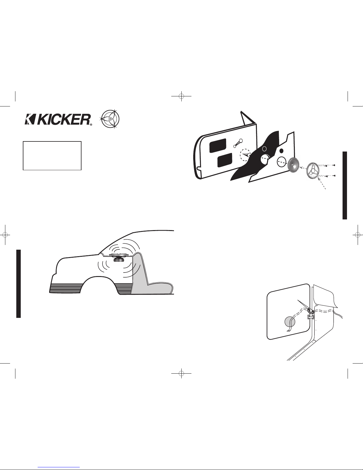
INSTALACIÓN
TweeterMontaje
El altavoz se puede montar uno de tres maneras: limpía, la superficie y montar angulado. Para
aplicaciones de montar de limpíe, se refiere por favor a la ilustración en la Figura 5. Escoja una
ubicación plana en el panel con el espacio detrás del panel para permitir el espacio para la tuerca
que monta. Después que verificar los espacios libres, cortan el diámetro 1 9/16” (4cm) de hoyo
que monta en el panel. Coloque la tuerca más corta que monta detrás del panel. Sólo utilice la
tuerca más larga que monta si el espesor de entrepaño prohibe el uso de la tuerca más corta
que monta. Alimente el cable por el reborde opcional de tweeter, el hoyo en el panel y la tuerca
que montan. Monte el tweeter enroscando la tuerca que monta en el tweeter.
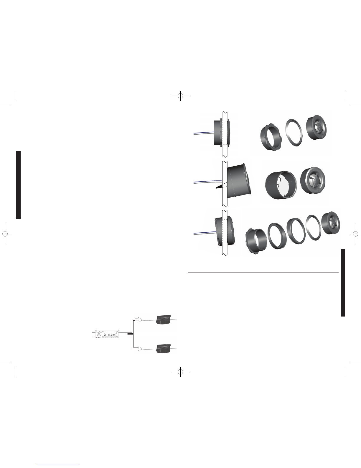
Para aplicaciones de montar de angulado-superficie utiliza la copa de angulado-superficie del
monte como una plantilla y pre-taladro dos 7/64” (2.5mm) hoyos de tornillo para conectar la copa
de angulado-superficie del monte al panel, y un 5/16” (8mm) hoyo para los cables del altavoz. Un
M3 tornillo se suministran para conectar la copa de superficie del monte al panel. Posicione el
tweeter sobre la copa de angulado-superficie del monte y lo aprieta en posición. Vea la Figura 6.
Para montar angulado las aplicaciones escogen una ubicación plana en el panel con el espacio
detrás del panel para permitir el espacio para la tuerca que monta y el anillo del ángulo de
espalda. Después que verificar los espacios libres, cortan el diámetro 1 9/16" (4cm) de hoyo que
monta en el panel. Coloque el anillo anterior del ángulo (no queda por el tweeter más largo que
monta tuerca) delante del panel. Coloque el cable del altavoz y el tweeter por el anillo anterior del
ángulo y en el panel. Coloque el cable del altavoz por el anillo del ángulo de espalda (los ataques
por el tweeter más largo que monta tuerca), coloca el anillo del ángulo de espalda sobre el
trasero del tweeter, y de la alineación la parte estrecha del anillo anterior del ángulo para el ángulo
preferido de la operación. Coloque el cable del altavoz por el tweeter más largo que monta tuerca
y aprieta flojamente la tuerca que monta alrededor del tweeter. Gire todas las partes al unísono
hasta que el tweeter esté angulado en la dirección deseada. Asegure la asamblea apretando el
tweeter que monta tuerca. Vea la Figura 7.
Cabelado
Es fácil conectar los cables suministrados a los Altavoces de la serie DS de Kicker. Monte el paso
externo en una ubicación libre de agua y componentes mecánicos del vehículo con los tornillos
encerrados. Los conectores positivos y negativos en los altavoces son terminados con
conectores de las formas y los tamaño diferentes que conectan a los conectores externos del
paso. Después de que conectar los altavoces al paso externo, conecten el paso externo a la
unidad fuente o el amplificador de acuerdo con su manual. Para la referencia, el alambre gris es
positivo y el alambre negro es negativo en el paso externo.
Cableadodedosaltavocessistemascomponentesaunsolocanal
Los altavoces sistemas componentes modernos de alto rendimiento tienen menor resistencia de
CC que la que había antes. Los altavoces de la serie DS de Kicker tienen una impedancia
nominal de 4 ohmios y funcionan con cualquier unidad fuente o amplificador diseñado para
operar con una carga de 4 ohmios. Si desea usar dos altavoces sistemas componentes (dos
altavoces de frecuencias medias e dos
tweeters) de la serie DS en cada canal de
su unidad fuente o amplificador, conecte los
altavoces en serie, tal como se muestra
abajo. Esto mejorará la calidad del sonido,
reducirá la distorsión armónica total y
aliviará la carga térmica en la unidad fuente
o amplificador. Esto puede prevenir un
amplificador de apagar, debido a la red de
circuitos de protección.
DS680.2
6x8 (160x200)
3/4 (20)
Titanio
4 (3)
90 (45)
90
40-21k
5x7 3/16 (12.7x18.3)
2 3/8 (6)
2 3/4 (7)
1 9/16 (4)
12, 4000
12, 4000
0, 3 & 6
No
Rendimiento
Modelo:
Tamaño del woofer, plg (cm)
Tamaño del tweeter, plg (cm)
Material del diafragma del tweeter
Impedancia nominal, ohmio (Resistencia de CC, ohmio)
Procesamiento máximo de potencia, vatios (RMS)
Sensibilidad [SPLo], dB @ 1W, 1m
Gama efectiva de frecuencias, Hz
Diámetro del agujero de montaje, plg (cm)
Profundidad de montaje superior, plg (cm)
Profundidad de montaje inferior, plg (cm)
Limpíe Montar el Diámetro del agujero de tweeter, plg (cm)
Paso alto, dB por octava, en la Frecuencia, Hz
Paso bajo, dB por octava, en la Frecuencia, Hz
Alta Frencuencia interruptor de Atenuación, dB
Rejillas de cierra-por
Figura 5
DS650.2
6.5 (165)
3/4 (20)
Titanio
4 (3)
120 (60)
90
35-21k
5 1/2 (14)
1 13/16 (4.6)
2 (5.1)
1 9/16 (4)
12, 4000
12, 4000
0, 3 & 6
Sí
Montar limpíe
Angulado- superficie
montar
Montar angulado
Tuercamáscorta quemonta
Copadeangulado-superficie del monte
Tuercamáslarga quemonta
Anillo del ángulo deespalda
Anillo anteriordel ángulo
Panel
Panel
Panel
Rebordedetweeter (opcional)
Tweeter
Tweeter
Rebordedetweeter (opcional)
Tweeter
Unidad fuente o amplificador
Alta Frencuencia interruptor
deAtenuación(0, 3 & 6dB)
DosDS altavoces sistemas
componentes conectaron
en la serie aunsolo canal
Paso externo
RENDIMIENTO
Figura 4
Figura 6
Figura 7
M3 Tornillo
07192007+07DS
2007 DS Components Multilingual a01.qxp 11/12/2008 3:47 PM Page 5