Kikawa KH-IC Series User manual

!
Installation & Operation Manual
!
!
!
!
!
!
!
ISO9001 Certified
KIKAWA PUMP CO., LTD.
KH-IC Series
Inverter-Controlled Pump

-1-
§ GENERAL DESCRIPTION
Inverter based variable speed constant pressure
pump control.
Soft start and stop functions ensuring quiet
operation and water hammer elimination.
Special design integral intelligent energy-saving
control function.
§ APPLICATION CONDITIONS!
Ambient Temperature:+2 ºC ~ +40 ºC
Water Temperature:+2 ºC ~ +40 ºC
Maximum Input PressureĈ6 kg/cm2
Maximum Output Pressure:10 kg/cm2
Motor ProtectionĈIP 54
Motor Insulation ClassĈF
§ CONSTRUCTION
Item Name Description Item Name Description Item Name Description
1 Motor 2-Pole/1or 3 Phases 10 Suction Cone SUS-304 19 Base S45C
2 Outlet Casing FC-200 11 Shaft Sleeve SUS-304 20 Base Bolt S45C
3 Shaft S45C & SUS304 12 Diffuser SUS-304 & Teflon 21
Check Valve
Bronzer
4 Mechanical Seal NBR or VITON 13 End Sleeve SUS-304 22 Pressure Gauge
5 Spring Guide SUS-304 14 Lock Nut SUS-304 23 Pressure Tank
6* Washer SUS-304 15 Inlet Casing FC-200 24 Control Box
7 Seal Gasket Teflon 16 Bolts SUS-304 25 Pressure Sensor 4-20mA
8 Impeller SUS-304 17 Priming Plug FC-200 26 Bolts SUS-304
9 Shaft Sleeve SUS-304 18 Drain Plug FC-200
* For all KH04 & Single Stage KH08/12 Models only
KH02/04
KH08/12

-2-
§ ELECTRICAL WIRING / PANEL DESCRIPTION
1HP◎ă2HP
!
!
!
!
!
!
!
!
!
!
!
!
!
!
!
!
!
!
!
!
!
!
!
!
◎3HPă5HP
!
!
!
!
!
!
!
!
!
!
§ INSTALLATION AND PINPING!
1. Installation site must be dry with good
ventilation and adequate space for future
maintenance and service. The pump must be
mounted and bolted securely for stable
operation.!Suitable shelter is recommended, if
the pump is mounted outdoor, to prevent direct
sunlight or raining, and be careful not to allow
the foreign objects into the motor cooling cover.!
2. Pump shall be installed as close as to the water
supply to minimum the suction lift. The
horizontal piping between water supply and
pump must pitch upward to avoid the air lock.
3. Check valve or foot valve is required in suction
piping, if pump is installed above supply water
level,
4. All pipe joints, especially in the suction pipe,
muse be sealed well. Leakage in the suction
pipe will damage the suction lift, and form air
lock. Leakage in the discharge pipe will cause
the pump ON/OFF frequently.
5. Be careful not to allow the foreign objects
(adhesive gum, dirt, sand, etc.)into the pump,
or the pump will be damaged and shorten the
life.
Up /Down Key
(Parameters Editing
and Selection)
Setting Head
(
M
)
Output Head
(
M
)
Function
Disabled
Forward
Indicator
Stop
Indicator
Function
Display
Run
Indicator
Stop/
Reset
Data
Enter
Data
Enter
Stop Key
(Indicator)
Run Key
(Indicator)
Mode
Indicator
Output
Head
(kg/cm2)
Function
Display
Setting
Head
(kg/cm2)
Mode
Selector
Function
Disabled
Function
Disabled
Up /
Down!

-3-
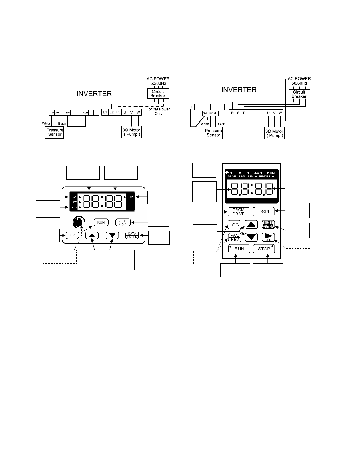
§ ELECTRICAL CONNECTION!
1. Every installation requires an accessible
appropriate rated circuit breaker for future
maintenance. Leakage circuit breaker is also
required in the environment with high humidity.
2. Verify that the supply power voltage and HZ
match the inverter input requirements.
Electrical wiring shall be done in accordance
with the local electrical code by a competent
electrician.
!
!
3. The motor/pump will enter the running mode
automatically after the power ON. For any
failures caused by abnormal electrical power
supply, reset the inverter (disconnect the power
at least 1 minute, for the inverter LED display
off), and then set the power ON.!
4. Good ventilation for the control box is important
to prevent the overheating of inverter and
resulting failures.!
!
§ OPERATION PROCEDURE
1. Pump must be primed by feeding the pump
casing and suction pipe with water before
starting the pump to avoid damage of pump
parts, especially the mechanical seal.
◎For the pump with water supply above the
pump level, remove the pump priming plug,
and put it back securely when the water
overflow from pump priming hole. Vent any
air trapped in supply pipe or casing by
opening the valves in discharge pipe.
◎For the pump with water supply below the
pump level, remove the pump priming plug,
and fill the pump and suction pipe with
water. Any air trapped in suction pipe and
casing must be removed.!
2. Insert a screwdriver into motor shaft end, and
turn the shaft several turns clockwise to check
whether the pump can be rotated freely. If not,
disassemble and clean the pump chamber.
3. Double check the voltage and wiring of the
motor power and then turn the power switch ON.
Open faucet or water appliances on the
discharge piping side. The water should be
delivered after several seconds.
4. If the water does not be delivered after several
minutes, turn off the pump immediately. Repeat
step 2 to pour water into the pump and suction
piping, and switch power ON and OFF
continuously.
5. Once the water is pumped out, close and open
the water appliances on the discharge side
repeatedly to check automatic ON/OFF
operation.
6. When re-start the pump after long term shut
down, please repeat step1~5 to ensure the
normal operation.
§ OUTPUT HEAD SETTING
!
!
!
!
!
¾Step 1ĈMake sure that the inverter display is in
“Head Mode”. If not, press
key continuously until the “Head
Mode” is displayed.
¾Step 2ĈPress or continuously to
adjust the “Setting Head” shown on
the right screen Ą
¾Step 3ĈPress to save the setting.
!
CAUTION
Improper pressure setting will cause pump
failure. Pressure setting too high will fail to stop
while too low will fail to start.

-4-
§ TROUBLE SHOOTING
!
CAUTION
Most of failures caused by temporal abnormal electric power supply or inlet
water shortage can be solved by resetting the inverter. To reset the inverter,
disconnect the electric power al least 1 minute (time required for inverter
LED display off) and set the power “ON” again. For special installation in
which the parameters must be modified, press “Stop/Reset” key first to
enter the edit mode.
!
Fault Description Causes and Corrective Actions
Blank Inverter LED Display Check electric power source.
Pump fails to start Output pressure setting two low.
“Restart Deviation (8-29)” setting too high; lower of valve
properly.
Pump gives reduced output or no
water is discharged
Leakage in suction piping and lose suction head.
Air-locked in suction piping or pump chamber. Refill the pump
and suction piping, or evacuate the air by opening the priming.
Pump fails to stop Output Pressure setting too high. Reduce the pressure setting
properly.
“Shut Down Tolerance Deviation (8-27)” setting too small.
Check air-locked or leakage in discharge piping and output
device.
Pump worn up, reduce the pressure setting or replace the
pump.
Pump cycles frequency while all
the faucets and valves are
closed.
Check leakage in discharge piping and output device.
Recharge pressure tank air up to 1~1.2 kg/cm2.
Display error code:
PIdE
Insufficiency inlet water supply and dry run protecting function
ON. Examine and improve the water supply, then reset the
inverter.
Pump actual output head too low. Increase the “Maximum
Output Tolerance Deviation (8-24) or (Cn52)” setting.
Pressure sensor malfunction. Replace the sensor with proper
specifications, if the pump output head do not vary with output
load change.
Display error code:
oL1
Improper motor running current, check if the motor locked.
Improper power supply, please refer to the inverter instruction
manual for detail.
Display error code:
Uv1, ov
Improper power supply, please refer to the inverter instruction
manual for detail.
Display error code:
oC
Inverter output short or grounded, please check the motor
wiring.
oH Inverter temperature too high because of improper ventilation,
please improve the inverter air ventilation.
!

-5-
!
§ INVERTER PARAMETERS
Parameter
Parameter Function Explanation Unit 1Ø 3Ø
Setting
Value
Maximum Output Tolerance Deviation % 8-24 Cn48 80
Output Failure Detection Time Sec. 8-25 Cn49 60
Output Failure Function Mode 8-26 Cn42 00
Shut Down Tolerance Deviation % 8-27 Cn50 08
Shut Down Detection Time Sec. 8-28 Cn51 15
Restart Deviation % 8-29 Cn52 75
Sleep Frequency % 8-30 Cn53 50
Sleep Off-Delay Time Sec. 8-31 Cn54 01
Dry Run Protection / Auto Reset Mode 8-32 Sn43 01
Dry Run Protection / Off Time Hr. 8-33 Cn63 0.5
!
!
ISO9001 Certified
KIKAWA PUMP CO., LTD.
CAUTION
For the details of keypad operations for parameters setting, please
refer to the original inverter instruction manual.
91HIC011/2012/09
Table of contents
Popular Water Pump manuals by other brands

Wilo
Wilo Yonos MAXO Installation and operating instructions

superior pump
superior pump 91025 owner's manual

pumpa
pumpa BLUE LINE PSP Series Translation of the original instruction manual

Amazon
Amazon B07SR159QF manual

Dover
Dover Wilden Original Series Engineering, operation & maintenance

Grundfos
Grundfos ALPHA1 L instructions

emaux
emaux SPV Series user manual

Geotech
Geotech Geopump I Series Installation and operation manual

Teral
Teral VKN-e Series instruction manual

Grundfos
Grundfos seg autoadapt Installation and operating instructions

Stuart Turner
Stuart Turner Flomate Mains Boost 46574 Installation & maintenance instructions

Varian
Varian HS-16 instruction manual