3
Important Safety Instructions 3-4
Safety Switch Indicator Light 4
Operating Instructions 5
Roto-Kut™ Cutter Installation 6
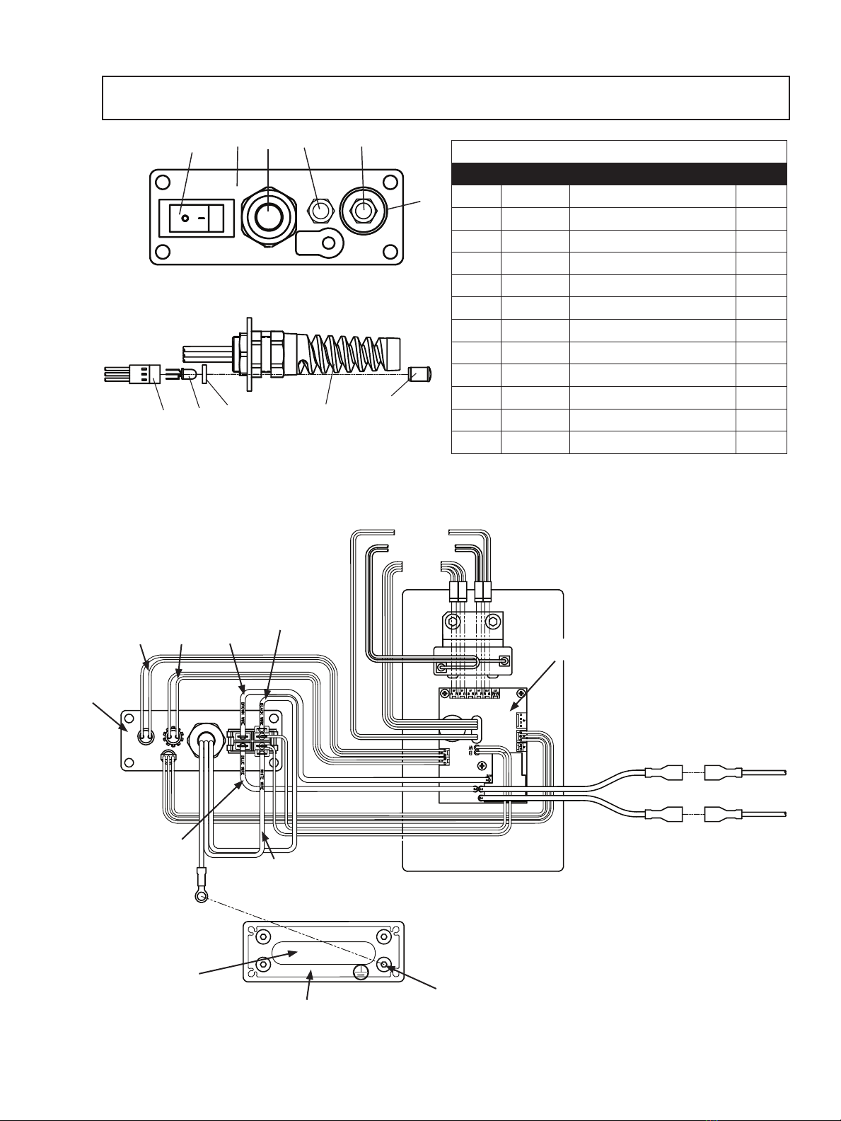
Control Panel Diagram
Drill Exploded View
Parts List
Motor Diagram & Parts List
Roto-Kut™ Series of Cutters
Limited Warranty Information
7
8
9
10
11
12
WARNING
IMPORTANT SAFETY INSTRUCTIONS
1. Work Area Safety
a) Keep your work area clean and well lit. Cluttered or
dark areas invite accidents.
b) Do not operate power tools in explosive
atmospheres, such as in the presence of fl ammable
liquids, gases or dust. Power tools create sparks which
may ignite the dust or fumes.
c) Keep children and bystanders away while operating a
power tool. Distractions can cause you to lose control.
2. Electrical Safety
a) Power tool plugs must match the outlet. Never modify
the plug in any way. Do not use any adapter plugs
with grounded power tools. Unmodifi ed plugs and
matching outlets will reduce risk of electrical shock.
b) Avoid body contact with grounded surfaces such as
pipes, radiators, ranges and refrigerators. There is an
increased risk of electric shock if your body is grounded.
c) Don’t expose power tools to rain or wet conditions.
Water entering a power tool will increase the risk of
electric shock.
d) Do not abuse the cord. Never use the cord for
carrying or unplugging the power tool. Keep the cord
away from heat, oil, sharp edges or moving parts.
Damaged or entangled cords increase the risk of electric
shock.
e) When operating a power tool outdoors, use an
extension cord suitable for outdoor use.
Use of a cord suitable for outdoor use reduces the risk
of electric shock.
f) If operating a power tool in a damp location is
unavoidable, use a residual current device (RCD) or
ground fault interrupter (GFI) protected supply. Use
of an RCD reduces the risk of electric shock.
3. Personal Safety
a) Stay alert, watch what you are doing and use
common sense when operating a power tool. Do not
use a power tool while you are tired or under the
infl uence of drugs, alcohol, or medication. A moment
of inattention while operating power tools may result in
serious personal injury.
b) Use personal protective equipment. Always wear eye
protection. Protective equipment such as a dust mask,
non-skid shoes, hard hat or hearing protection used for
appropriate conditions will reduce personal injuries.
Important Safety Instructions
Work Area
Keep your work area clean and well lit. Cluttered benches and
dark areas invite accidents.
Do not operate power tools in explosive atmospheres, such as
in the presence of flammable liquids, gases or dust. Power tools
create sparks which may ignite the dust or fumes.
Keep bystanders, children, and visitors away while operating a
power tool. Distractions can cause you to loose control.
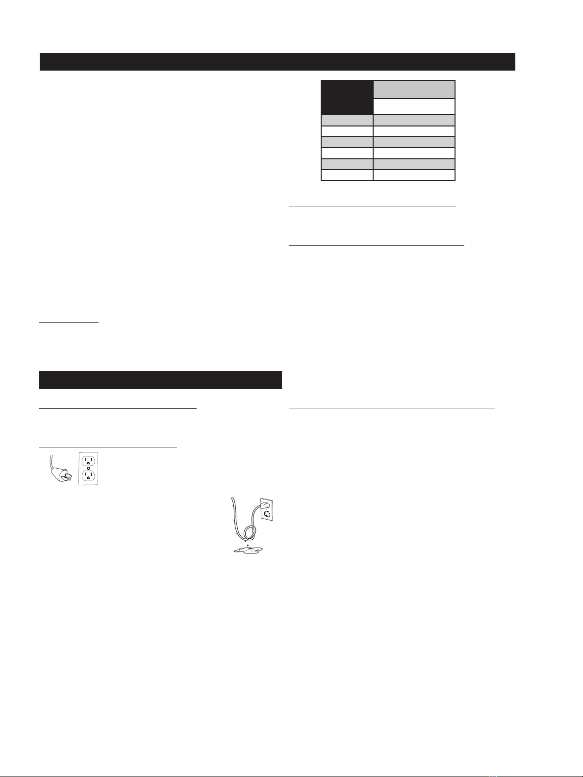
Electrical Safety
Grounded tools must be plugged into an outlet properly in-
stalled and grounded in accordance with all codes and ordi-
anaces. Never remove the ground prong or modify the plug in
any way. Do not us any adapter plugs. Check with a qualified
electrician if you are in doubt as to whether the outlet is prop-
erly grounded. If the tools should electrically malfunction or break-
down, grounding is provides a low resistance path to carry electricity
away from the user.
Avoid body contact with grounded surfaces such as pipes,
radiators, ranges and refrigerators. There is an increased risk of
electric shock if your body is grounded.
Don’t expose power tools to rain or wet conditions. Water enter-
ing a power tool will increase the risk of electric shock.
Do not abuse the cord. Never use the cord to carry the tools or
pull the plug from an outlet. Keep cord away from heat, oil, sharp
edges or moving parts. Replace damaged cords immediately.
Damaged cords increase the risk of eletric shock.
When operating a power tool outside, use an outdoor extension
cord marked “W-A” or “W”; These cords are rated for outdoor use
and reduce the risk of electrical shock.
Personal Safety
Stay alert, watch what you are doing and use common sense
when using a power tool. Do not use tool while tired or under
the influence of drugs, alcohol, or medication. A moment of inat-
tention while operating power tools may result in serious personal
injury.
Dress properly. Do not wear loose clothing or jewelry. Contain
long hair. Keep your hair, clothing, and gloves away from moving
parts. Loose clothes, jewelry, or long hair can be caught in moving
parts.
Avoid accidental starting. Be sure switchis off before plugging
in. Carrying tools with your finger on the switch or plugging in tools
that have the switch on invites accidents.
Remove adjusting keys or switches before turning the tool on. A
wrench or a key that is left attached to a rotating part of the tool may
result in personal injury.
Do not overreach. Keep proper footing and balance at all times.
Proper footing and balance enables better control of the tool in unex-
pected situations.
Use safety equipment. Always wear eye production. Dust
mask, non-skid safety shoes, hard hat, or hearing protection
must be used for appropriate conditions.
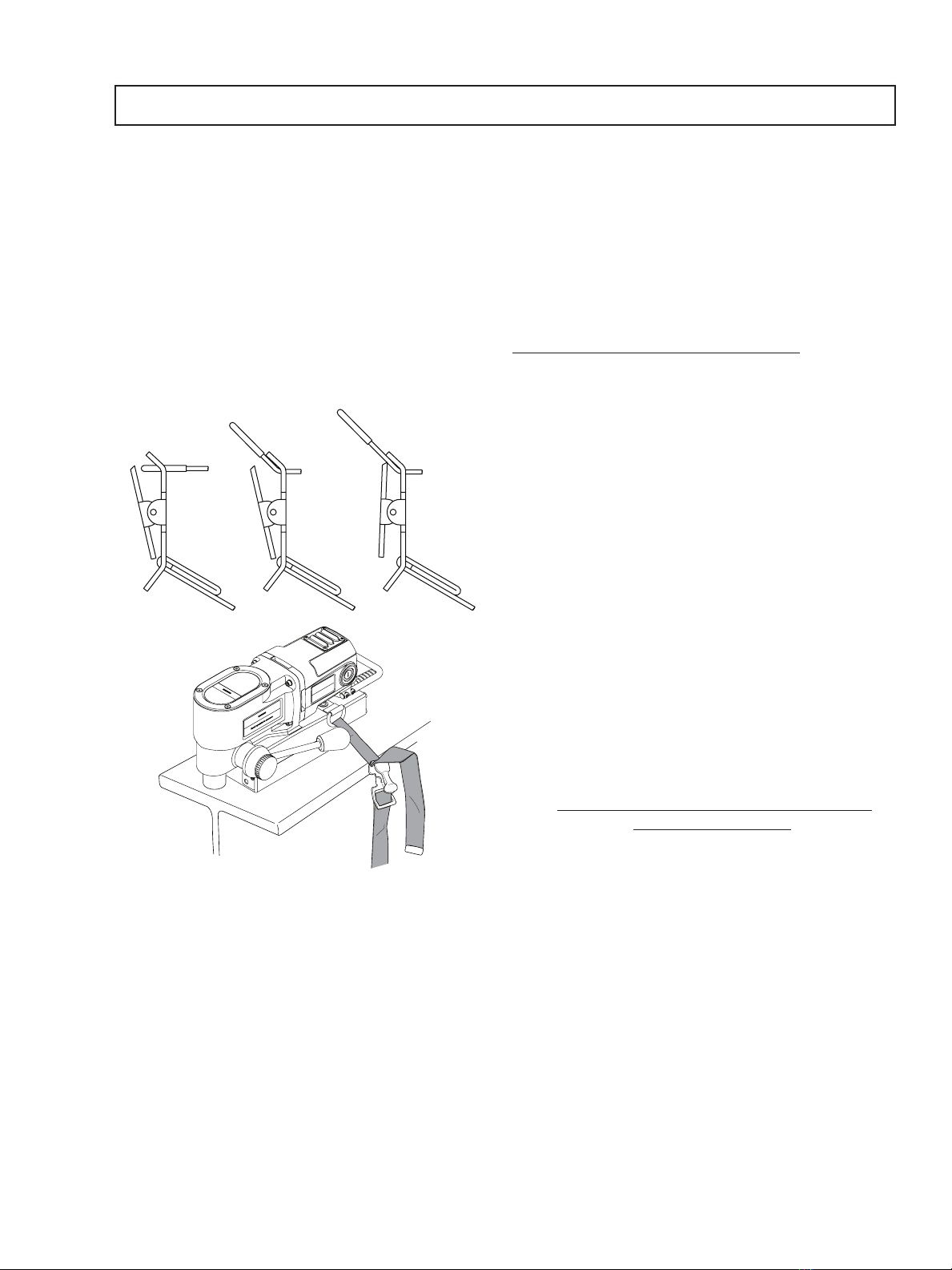
Always use safety chain. Mounting can release.
Tool Use and Care
Use clamps or other practical way to secure and support
the work piece to a stable platform. Holding the work by
hand or against your body is unstable and may lead to loss of
control.
Do not force tool. Use the correct tool for your application.
The correct tool will do the job better and safer at the rate for
which it is designed.
Do not use tool if switch does not turn it on or off. Any
tool that cannot be controlled with the switch is dangerous and
must be repaired.
Disconnect the plug from the power source before making
any adjustments, changing accessories, or storing the
tool. Such preventive safety measures reduce the risk of start-
ing the tool accidentally.
Store idle tools out of reach of childern and other
untrained persons. Tools are dangerous in the hands of
untrained users.
Maintain tools with care. Keep cutting tools sharp and
clean. Properly maintained tools, with sharp cutting edges are
less likely to bind and are easier to control.
Check for misalignment or binding of moving parts, break-
age of parts, and any other condition that may affect the
tools operation. If damaged, have the tool serviced before
using. Many accidents are caused by poorly maintained tools.
Use only accessories that are recommended by the manu-
facturer for your model. Accessories that may be suitable for
one tool, may become hazardous when used on another tool.
Service
Tool service must be performed only by qualified repair
personnel. Service or maintenance performed by unqualified
personnel could result in a risk of injury.
When servicing a tool, use only identical replacement
parts. Follow instructions in the Maintenance section of
this manual. Use of unauthorized parts or failure to follow
Maitenance Instructions may create a risk of electric shock or
injury.
WARNING: Read and understand all instructions. Failure to follow all instructions listed below,
may result in electrical shock, fire and/or serious personal injury.
c) Prevent unintentional starting. Ensure the switch
is in the off-position before connecting to a power
source, picking up or carrying the tool. Carrying
power tools with your fi nger on the switch or energizing
power tools that have the switch on invites accidents.
d) Remove any adjusting keys or wrenches before
turning the power tool on. A wrench or a key that
is left attached to a rotating part of the power tool
may result in personal injury.
e) Do not overreach. Keep proper footing and
balance at all times. This enables better control of
the power tool in unexpected situations.
f) Dress properly. Do not wear loose clothing or
jewelry. Keep your hair and clothing away from
moving parts. Loose clothes, jewelry or long hair
can be caught in moving parts.
g) If devices are provided for the connection of
dust extraction and collection, ensure these are
connected and properly used. Use of dust
collection can reduce dust-related hazards.
h) Do not let familiarity gained from frequent use
of tools allow you to become complacent and
ignore tool safety principles. A careless action
can cause severe injury within a fraction of a second.
i) Always use the safety strap. The magnet can
unexpectedly release from the work surface.
4. Power Tool Use and Care
a) Do not force the power tool. Use the correct
power tool for your application. The correct power
tool will do the job better and safer at the rate for
which it is designed.
b) Do not use the power tool if the switch does
not turn it on or off. Any power tool that cannot be
controlled with the switch is dangerous and must
be repaired.
c) Disconnect the plug from the power source
before making any adjustments, changing
accessories or storing power tools. Such
preventative safety measures reduce the risk of
starting the tool accidently.
(Continued on page 4)
Save all warnings and instructions
for future reference.
Always wear eye
protection while using
cutting tools, or in the
vicinity of cutting.
The slug is ejected at
the end of the cut. Do
not aim the cutter or
arbor so that the ejected
slug may hit someone
around, or below you.
To prevent electric
shock, do not use
power tools near wet
areas, or where the
power tool may become
wet.
Do not stare at the
operating light.
Read all safety warnings, instructions, illustrations and specifi cations provided with
this power tool. Failure to follow all instructions listed below may result in electric shock, fi re
and/or serious injury.
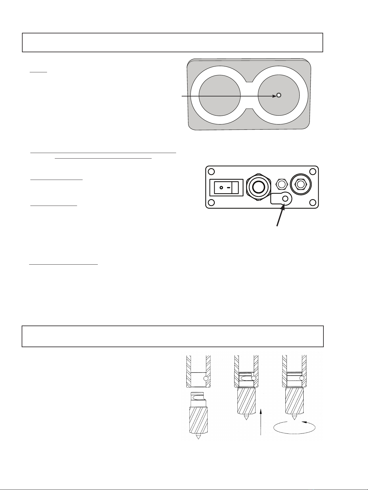
WARNING:
Cutters are sharp. Wear
gloves when installing
or removing a cutter
from the arbor. Do not
grab a rotating cutter.