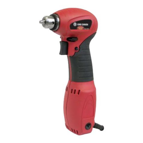
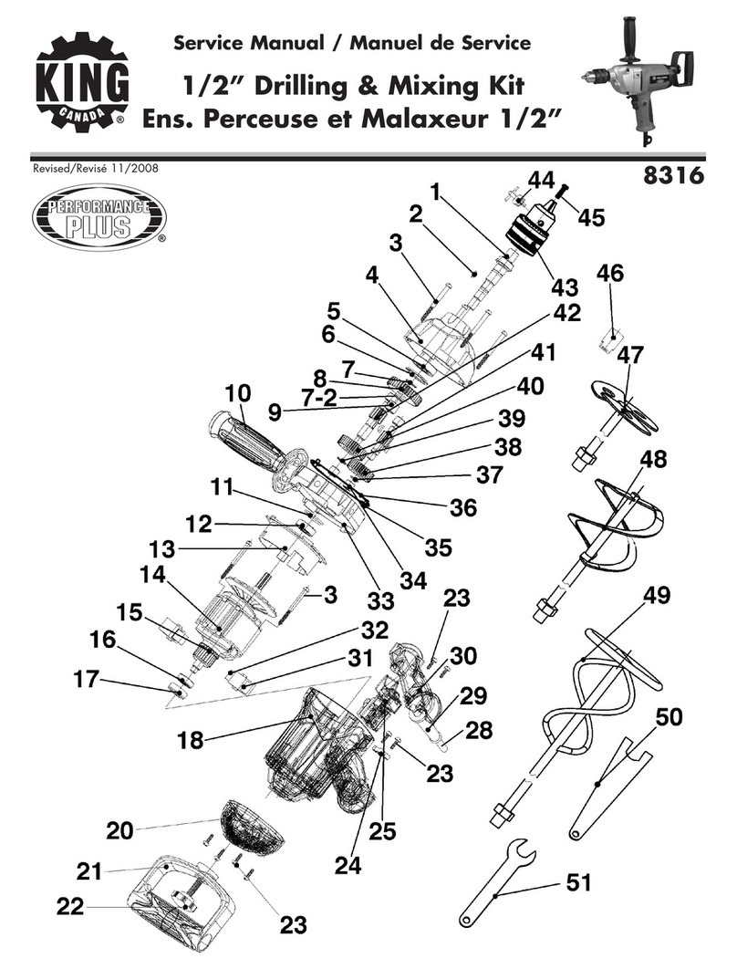
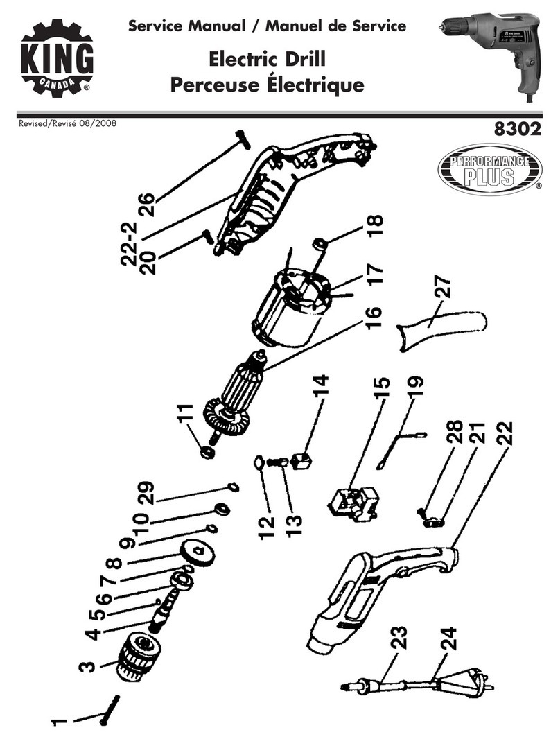
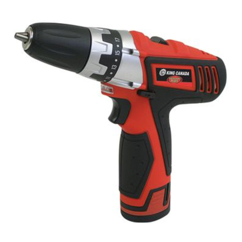
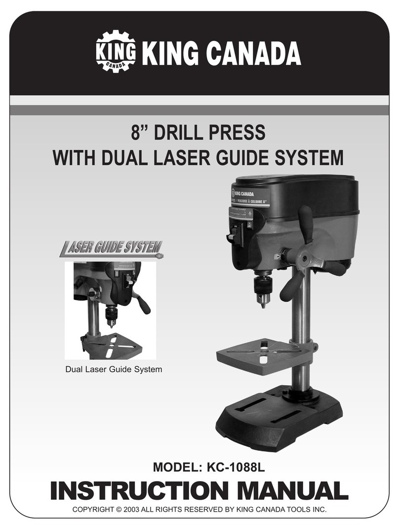
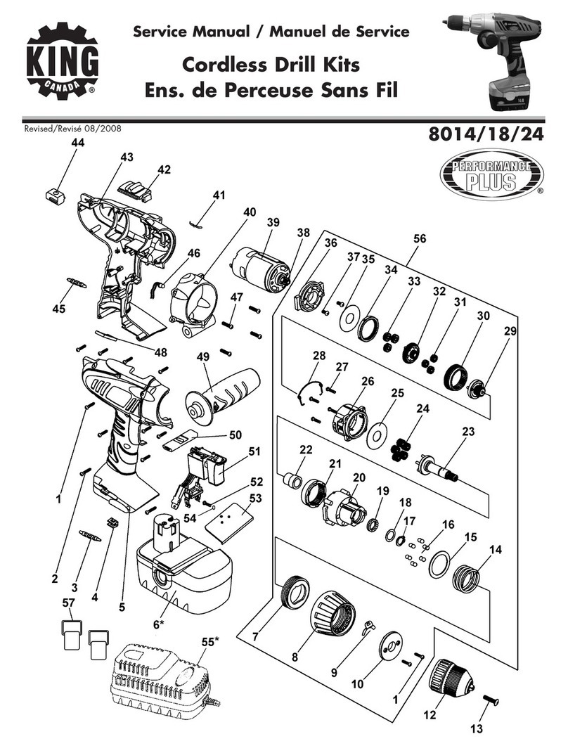
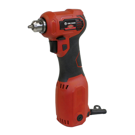
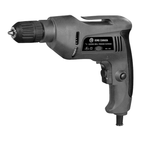
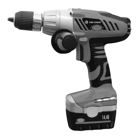
GETTING TO KNOW YOUR HAMMER DRILL
A. Trigger
B. Forward /reverse switch
C. Chuck
D. Variable speed control
E. Lock-on button
F. Hammer mode switch
G. Depth stop gauge
FIXING & CHANGING DRILL BIT
•Turn the Hammer Drill off first.
•Clean the shivers and any other foreign objects away from the bit and chuck, otherwise
the bit might not be tightened securely and thus will induce severepersonal injuries.
•Insert the bit into the chuck, make surethat the bit
is in as far as it will go.
•Place the chuck key in one of the 3 holes, then
tighten all three jaws of the chuck by rotating the
chuck key clockwise.
WARNING:More than 1/3 of the general length of
the drill bit must protrude out of the chuck jaws.
•When dismantling the drill bit, loosen the three jaws with the chuck key, then remove the
drill bit.
NOTE:Always remove chuck key before restarting drill.
SWITCH ACTION
WARNING:Beforepluging into power source, make surethe trigger switch can be
pressed down smoothly and will return to its “OFF” position when the switch button is
released. The drill is equipped with a “Lock-On” button which is convenient when
continuous drilling for extended periods of time is
required.
•Press down trigger switch to start work, and release to
stop work.
• To have continuous operation, press down the trigger
switch and push the “Lock-on” button located on the
side of the handle, then release the trigger.
•The drill will continue running after the release of the “Lock-on” button. Tostop
working, release the trigger switch.
•When “Lock-on” feature engaged during use and the drill becomes disconnected from
the power supply, disengage the “Lock-on” feature immediately.
OPERATION OPERATION
REVERSIBLE ROTATING DIRECTION
The rotating direction of the drill is controlled by a lever
located above the trigger.
•With the drill held in normal operating position, direction
of rotation lever should be positioned to the right of the
trigger for forward (F) drilling operation.
•Direction of rotation is in reverse (R) when the lever is to
the left of the trigger.
NOTE: The drill will not operate unless the rotation lever is pushed fully to the left or right.
SPEED CONTROL
The drill can be preset to match material requirements by
using speed control selector.
•Hold the drill in normal operation, and turn the variable
speed control selector clockwise to increase the speed
and torque of the drill. Turn counter-clockwise to
decrease the speed and torque.
NOTE: If the variable speed control selector is fully turned
in counter-clockwise direction (Zero Setting), Your drill may not run.
• To lock the switch on at a given speed, depress the trigger, push in and hold the
“Lock-on” button then release the trigger.Next, adjust the variable speed control
selector until the desired speed is reached.
•When you desirenot to use the variable speed control selector turn it in the fully
clockwise direction. This will allow the speed of the drill to be fully controlled by the
amount of trigger depression.
•Speed control guidelines:
1) Low speed - is ideal when minimum speed is required. e.g.: Making holes without
center punch, driving screws, mixing paint or drilling ceramics.
2) Medium speed - is suitable for drilling hardmetals, plastics and laminates.
3) High speed - Perfect for when maximum power is required. E.g.: Drilling in wood, soft
metals like aluminum, brass or copper.
WORKING MATERIALS
The working materials should be within: “wood, metal, resin boards, concrete”.
•When drilling hard, smooth surfaces, use a center punch to mark the desired hole
location. This will prevent the drill from slipping offcenter as the hole is started.
•The working material should be secured in a device or with clamps to keep it from
moving as the drill bit rotates.
•When drilling concrete and masonry, move the function changeover device to “hammer
icon”. Toachieve the maximum impact when drilling into maconry.
F
R
