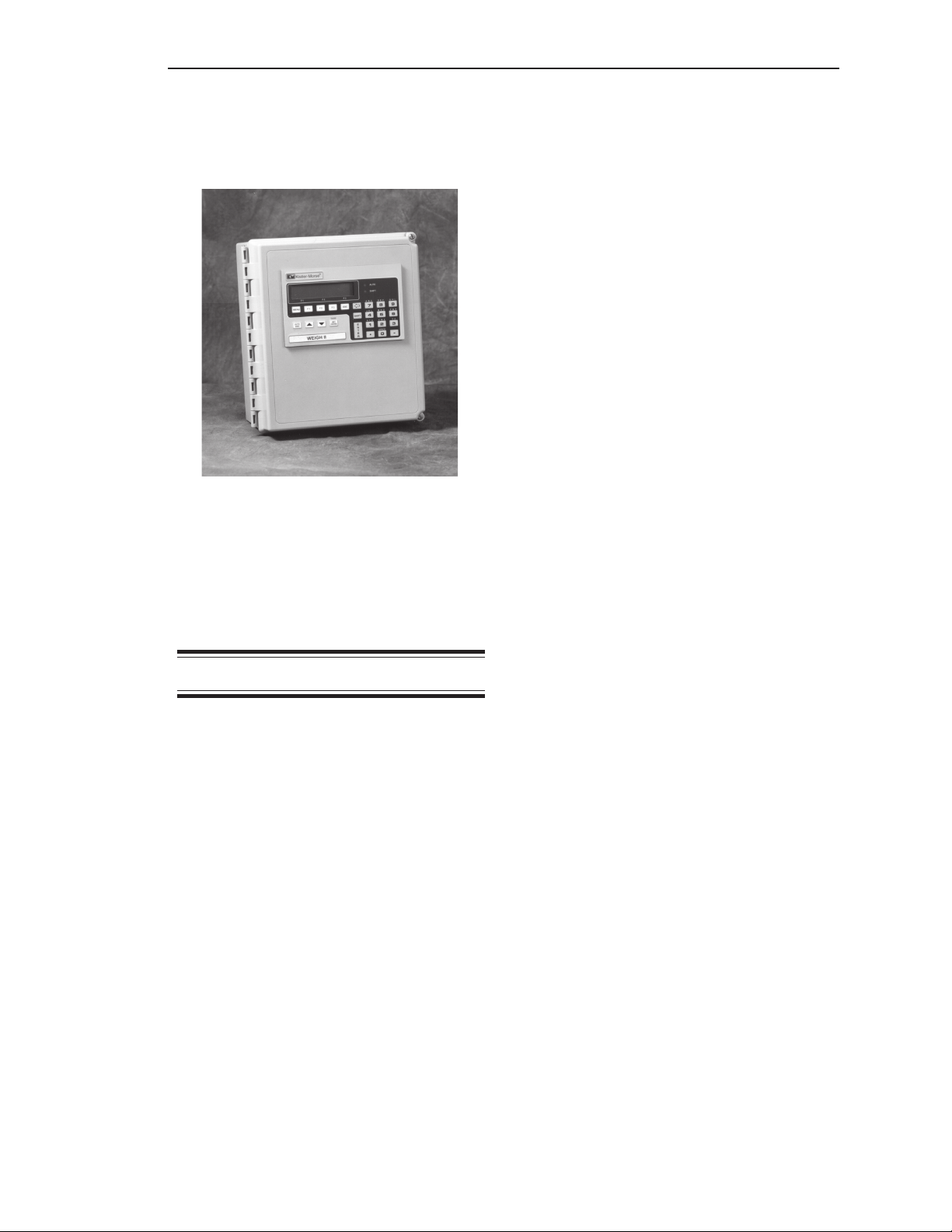
Chapter 2. Hardware Installation
General Information
This chapter provides instructions on how to
install and wire the Weigh II.
WARNING
If the Weigh II has been connected
to power, disconnect it before
proceeding. Deactivate power to
the controlled devices to prevent
equipment damage or personal
injury.
Read all instructions before beginning
installation. It is important that all instructions
are followed carefully to ensure that the
equipment is properly mounted and wired.
Unpacking and
Inspection
Carefully remove the components of the
Weigh II from the shipping container and
place them on a flat surface. Visually inspect
for damage that may have occurred during
shipment. If any damage is evident, note it on
the shipping receipt. Report the damage to
the carrier and to Kistler-Morse immediately.
Store the shipping container and packing
material for later use in the event the Weigh II
must be returned to the factory.
Mounting the Weigh II
When mounting the Weigh II, be sure there is
enough clearance to open the front door.
Removal and insertion of the modular PCBs
as well as wiring of the sensors and the
PCBs are done through the front of the unit.
The hardware used to mount the Weigh II is
provided by the customer. The Weigh II
enclosure dimensions are shown in
TI-SP.W2-01 in Appendix F, Technical
Drawings. Refer to Appendix A, Product
Specifications, for environmental specifica-
tions before mounting the Weigh II.
Follow this procedure to mount the Weigh II:
1. Hold the Weigh II enclosure against the
wall in the desired location and mark the
positions of the mounting holes. Place the
Weigh II in a safe place.
2. Drill the mounting holes in the wall.
3. Attach the Weigh II to the wall using
hardware that will secure it firmly
in place.
Wiring the Weigh II
This section describes how to wire power to
the Weigh II and how to wire the optional
PCBs. Installation and wiring of the Kistler-
Morse sensors are described in the appli-
cable sensor installation manuals.
Wire routing requirements for the AC and
DC versions of the Weigh II differ, as de-
scribed below:
•AC Version — Route the AC power cable
and the setpoint cables separate from the
low-level signal cables. Doing
so will avoid electrical interference in
the sensor signals and the communica-
tions signals.
•DC Version — Route the DC power cable
separate from any AC power cable and
coaxial cable. Route the setpoint cables
separate from the DC power cable and the
low-level signal cables. Doing so will avoid
electrical interference in the communica-
tion signals. Note that you can route the
DC power cable with the low-level signal
cables.
Drilling Holes in Enclosure
CAUTION
Remove the electronics before drilling
holes in the enclosure. Drill the holes
through the bottom or through the side
of the enclosure. DO NOT drill holes
through the top as this may allow
moisture seepage, which can damage
the electronics.
Chapter 2. Hardware Installation
2-1