Solar Garden Light Essentials
www.kitronik.co.uk/2134
How the Solar Garden Light Works
The garden light uses a solar cell to charge a
rechargeable battery during the day. At night,
when the light level has dropped, the circuit
switches from charging the battery to discharging
the battery through a high brightness LED.
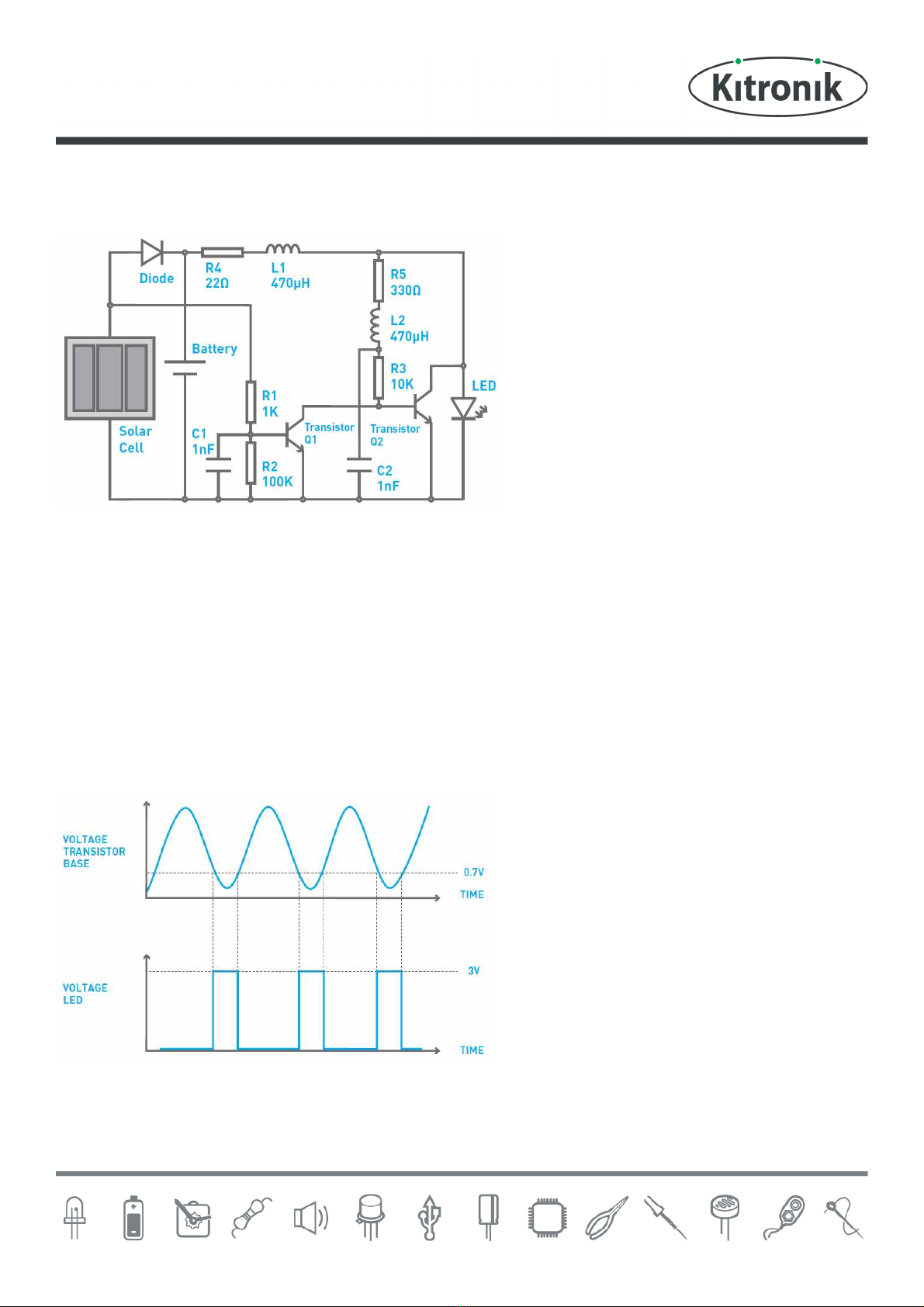
The solar cell and the diode form the parts used to
charge the battery. When sunlight shines on the
solar cell, it produces enough power to charge the
battery. The diode is used to stop the battery
discharging back (as it only allows electricity to
flow in one direction) into the solar cell if there is
not enough sunlight falling upon (and therefore
not enough voltage generated by) the solar cell.
Resistors (R1) and (R2) and transistor (Q1) form the part of the circuit that switches the LED on when the light level
has fallen below the desired level.
When there is sunlight on the solar cell, the voltage it produces is enough to turn transistor (Q1) on (this keeps the
LED turned off). As the amount of sunlight falls, the voltage it produces falls until there is not enough to keep
transistor (Q1) turned on. The resistors (R1) and (R2) form a potential divider, which is used to feed only a
proportion of the voltage produced by the solar cell through to the transistor. This allows the point where the LED
comes on to be fine-tuned to the desired level.
Once activated, the remaining parts are used to power the LED. The LED requires around 3V to work but the battery
can only supply about 1.2V. In order to generate 3V for the LED, the circuit has been designed so that the LED is not
always on but when it is, 3V can be supplied.
This happens so fast that to the human eye, the LED
looks like it is always on. The inductor (L2) and the
capacitor (C2) form a resonant circuit that produces
an alternating signal as shown in the picture above.
When this alternating signal produces a voltage
above 0.7V it turns on the transistor (Q2), which
keeps the LED off. When this voltage drops below
0.7V, the transistor turns off and the LED comes on.
When it is on the inductor (L1), which has been
storing an amount of electricity, discharges into the
LED at the same time as the battery which produces
the extra voltage needed to give the 3V for the LED.
The resistors (R4) and (R5) have been selected to reduce the amount of power the LED drive circuit uses. This helps
to extend the battery life so that the light can last about ten hours from a good days charging in the summer. When
there is less daylight in winter, this time will be reduced.